Week 13
Networking and Communications
This week, we are going to learn about how to connect 2 or more boards with or without wires. The main idea for this week is that we have some way of communication between boards so that this understanding will help to to connect more boards when needed in different projects. The main reason that we need this is for following:
Location: We need networking to talk to any device of component which are not in same location, within a same device or globally away.
Parallelism: Rather than same board working for all the the works one concept of parallel works is having different boards in different location so that the board with less power can work in parallel.
Modularity: Networking is very helpful when the boards are in modular which is very easy to debug the board and understand the board.
Interference: If you keep different devices like motors and radios in same board where radio needs low noise, there might be interference which we can solve by breaking it apart and con
Types of connection:
Parallel: This the type of connection when the data transfers in parallel. These are fast but require wire equivalent to numbers of bits it is transferring.
Series: Data is sent by same wire but in series one after another. It is relatively slower but are cheap and easy to use. The examples of serial communication are as follows
SBUS
UART
I2C
SPI
USB, etc
So, in order to transfer the data, the device needs some kind of reference which separates one data from another or know when the data starts and where it ends. Depending upon the use of clock or not there are two types:
Synchronous:
If the communication uses reference of clock to transfer a data or a signal it is called synchronous communication. Here data is send bu one wire and the synchronized clock is send from another wire and the reading is done according to the clock. There are different types of synchronous communication protocol like Inter-Integrated Circuit(I2C) protocol or two wire interface and Serial Peripheral Interface (SPI). The details are explained below.
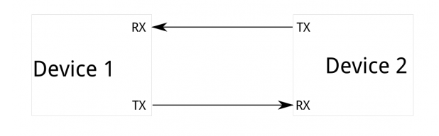
Asynchronous
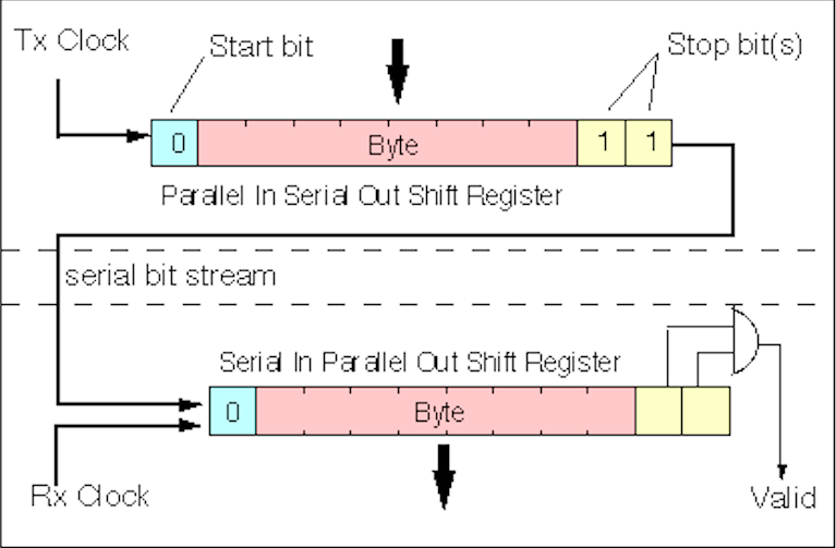
If the communication does not use reference of dedicated clock signal to transfer a data or a signal it is called asynchronous communication. So the question is how does it know when the data starts and ends. To solve this, there should be common configuration between the transmitter and receiver. The main configuration are
a. transmission speed in bauds/s, normally 9600 bauds/s is used
b. data length in bits, if 9600 bauds/s is used one bit is 104micro second
c. when to start and stop, there is low signal for start and high signal at the stop.
So the way it work is first when low signal is there it assumes the data is started. Once the signal is low, it goes 104uS and takes as the start of the data but to have a clean reading it goes in middle i.e half of the bit time i.e 52us to read the data the it continues reading until 8 bit and there is high signal again as a stop bit. Then the buffered data is pased to the other area of board. An example of Asynchronous communication is UART.
The one I will be doing is I2C type this week as this is simple connection. This is a type of synchronous communication protocol.
Individual Assignment
I2C Communication
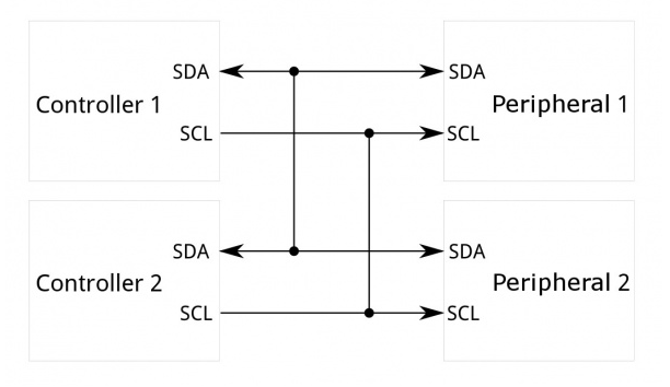
The Inter-Integrated Circuit (I2C) Protocol is a protocol intended to allow multiple "peripheral" digital integrated circuits ("chips") to communicate with one or more "controller" chips. Like the Serial Peripheral Interface (SPI), it is only intended for short distance communications within a single device. Like Asynchronous Serial Interfaces (such as RS-232 or UARTs), it only requires two signal wires to exchange information.
Why use I2C
Issue with UART
Because serial ports are asynchronous (no clock data is transmitted), devices using them must agree ahead of time on a data rate. The two devices must also have clocks that are close to the same rate, and will remain so--excessive differences between clock rates on either end will cause garbled data. Asynchronous serial ports require hardware overhead--the UART at either end is relatively complex and difficult to accurately implement in software if necessary. At least one start and stop bit is a part of each frame of data, meaning that 10 bits of transmission time are required for each 8 bits of data sent, which eats into the data rate. Another core fault in asynchronous serial ports is that they are inherently suited to communications between two, and only two, devices. While it is possible to connect multiple devices to a single serial port, bus contention (where two devices attempt to drive the same line at the same time) is always an issue and must be dealt with carefully to prevent damage to the devices in question, usually through external hardware. Finally, data rate is an issue. While there is no theoretical limit to asynchronous serial communications, most UART devices only support a certain set of fixed baud rates, and the highest of these is usually around 230400 bits per second.
Issue with SPI
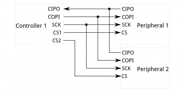
The most obvious drawback of SPI is the number of pins required. Connecting a single controller [1] to a single peripheral [1] with an SPI bus requires four lines; each additional peripheral device requires one additional chip select I/O pin on the controller. The rapid proliferation of pin connections makes it undesirable in situations where lots of devices must be connected to one controller. Also, the large number of connections for each device can make routing signals more difficult in tight PCB layout situations. SPI only allows one controller on the bus, but it does support an arbitrary number of peripherals (subject only to the drive capability of the devices connected to the bus and the number of chip select pins available). SPI is good for high data rate full-duplex (simultaneous sending and receiving of data) connections, supporting clock rates upwards of 10MHz (and thus, 10 million bits per second) for some devices, and the speed scales nicely. The hardware at either end is usually a very simple shift register, allowing easy implementation in software.
Protocols
Communication via I2C is more complex than with a UART or SPI solution. The signalling must adhere to a certain protocol for the devices on the bus to recognize it as valid I2C communications. Fortunately, most devices take care of all the fiddly details for you, allowing you to concentrate on the data you wish to exchange.
Basics
Messages are broken up into two types of frame: an address frame, where the controller indicates the peripheral to which the message is being sent, and one or more data frames, which are 8-bit data messages passed from controller to peripheral or vice versa. Data is placed on the SDA line after SCL goes low, and is sampled after the SCL line goes high. The time between clock edge and data read/write is defined by the devices on the bus and will vary from chip to chip.
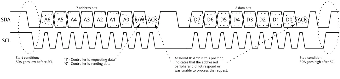
Start Condition
To initiate the address frame, the controller device leaves SCL high and pulls SDA low. This puts all peripheral devices on notice that a transmission is about to start. If two controllers wish to take ownership of the bus at one time, whichever device pulls SDA low first wins the race and gains control of the bus. It is possible to issue repeated starts, initiating a new communication sequence without relinquishing control of the bus to other controller(s); we'll talk about that later.
Address Frame
The address frame is always first in any new communication sequence. For a 7-bit address, the address is clocked out most significant bit (MSB) first, followed by a R/W bit indicating whether this is a read (1) or write (0) operation.
The 9th bit of the frame is the NACK/ACK bit. This is the case for all frames (data or address). Once the first 8 bits of the frame are sent, the receiving device is given control over SDA. If the receiving device does not pull the SDA line low before the 9th clock pulse, it can be inferred that the receiving device either did not receive the data or did not know how to parse the message. In that case, the exchange halts, and it's up to the controller of the system to decide how to proceed.
Data Frames
After the address frame has been sent, data can begin being transmitted. The controller will simply continue generating clock pulses at a regular interval, and the data will be placed on SDA by either the controller or the peripheral, depending on whether the R/W bit indicated a read or write operation. The number of data frames is arbitrary, and most peripheral devices will auto-increment the internal register, meaning that subsequent reads or writes will come from the next register in line.
Stop condition
Once all the data frames have been sent, the controller will generate a stop condition. Stop conditions are defined by a 0->1 (low to high) transition on SDA after a 0->1 transition on SCL, with SCL remaining high. During normal data writing operation, the value on SDA should not change when SCL is high, to avoid false stop conditions.
For further details about I2C, refer this link
Each secondary board has its own unique 7 to 10 bit address which master uses to identify them. Whenever master wants to send data it first generates a request which has particular address of that secondary board followed by the data. Every secondary board compares the address if matches with its own, responds to the master. Every message initiates with a start condition and ends with a stop condition.
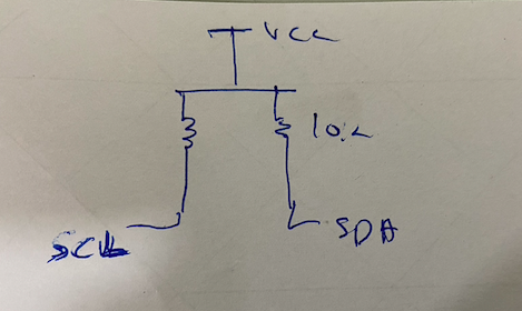
(Pull-up resistors with SDA and SCL are necessary in order to run this protocol. I did a mistake trying to connect two board without pull-up resistors in between which i learned from the data sheet)
Advantages:
1. Multiple masters and multiple slaves can be interfaced together
2. Only two wires are required for this communication
Disadvantages:
1. It is slower as compared to SPI because a lot of framing work is done within this protocol
My Assignment
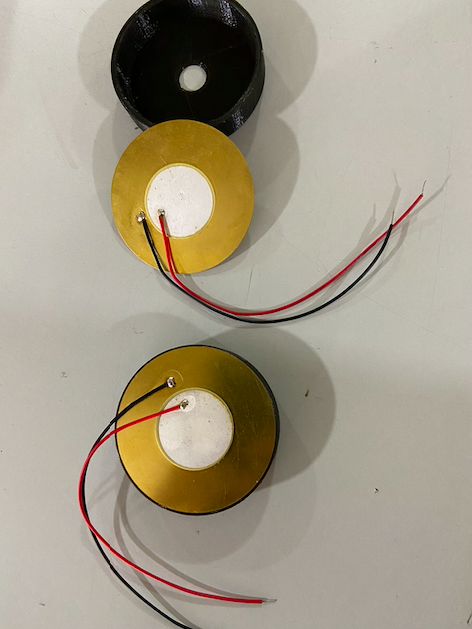
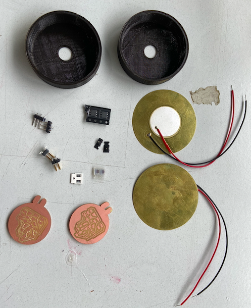
For the assignment, I decided to try something fun. I had recently seen codes with which people play music using an arduino. I wanted to know how it worked. I discussed with my colleague Saheen Palayi who had done something similar before. He told me that I could do that using a buzzer. Since I wanted to knwo more about how it works, I decided to make a buzzer. For this, I first took a couple of piezoelectric transducers from the inventory and 3D printed the case for it.
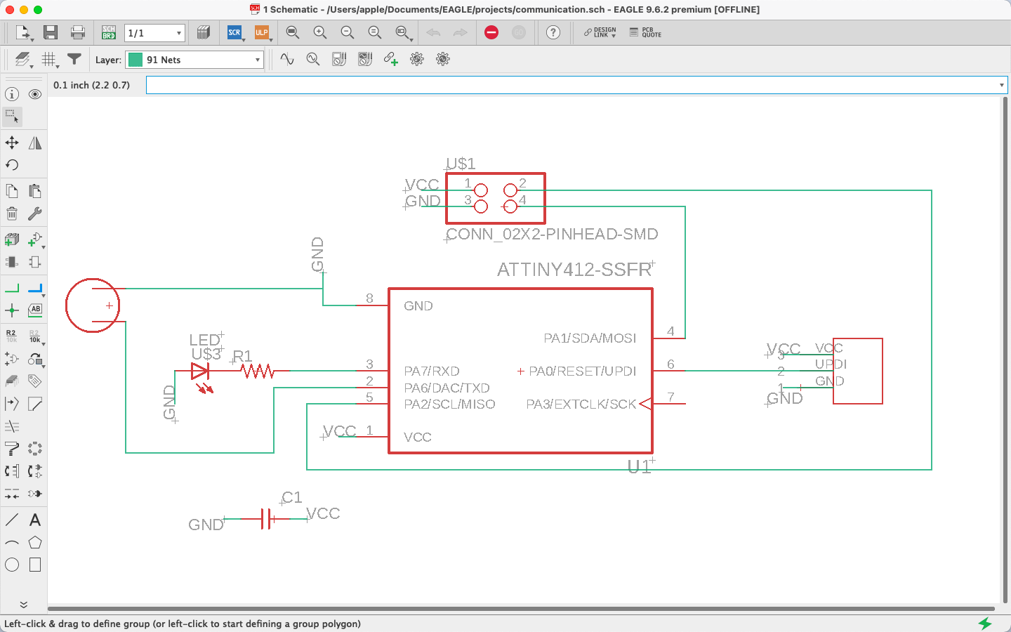
When the 3D printing was done, I went ahead to design the board that would play my music. I had checked a few codes online and estimated the size of similar codes and cross checked with the available microcontrollers in the lab. I figured out that I would be using the ATtiny 412 for this. I also figured I will give small bunny ears to the pcb when milling, and call them bunnies just for fun.
I designed the board using Autodesk Eagle
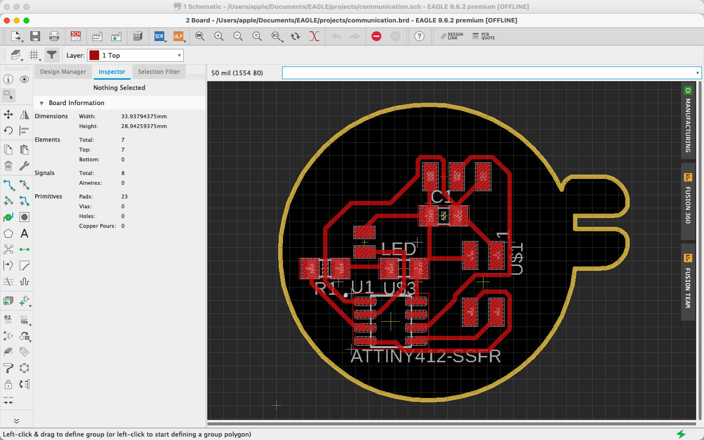
Once the design was completed, I milled the board using the Modella in our lab.
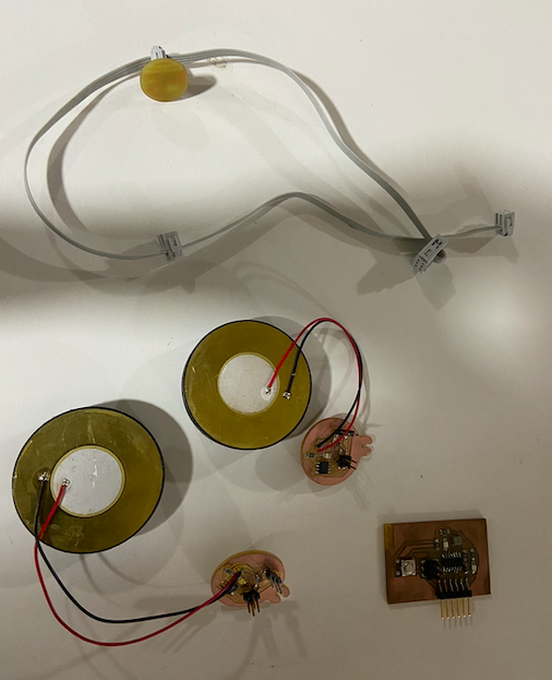
When the milling and soldering was done, I assembled the components getting it ready to be coded. For the Master board, I used the Hello Echo board that I had made during the Electronics Design week
After I had designed and milled my boards, my colleague mentioned the requirement of pull up resistors in the circuit. I used this documentation for reference and pull up resistor since it was already there.
Programming
Master code
#include
#include
#define button 8
int x=0;
boolean flag;
void setup() {
Wire.begin();
flag=false;
pinMode(button, INPUT);
}
void loop() {
if (digitalRead(button) == 1 && !flag)
{
flag=true;
if(x==0){x=1;}else{ if(x==1){x=0;}}
delay(300);
}
if(flag)
{
if(x==1)
{
Wire.beginTransmission(8);
Wire.write(1);
Wire.endTransmission();
delay(100);
Wire.beginTransmission(10);
Wire.write(0);
Wire.endTransmission();
}
if(x==0)
{
Wire.beginTransmission(8);
Wire.write(0);
Wire.endTransmission();
delay(100);
Wire.beginTransmission(10);
Wire.write(1);
Wire.endTransmission();
}
flag = false;
}
}
Bunny 1 Code
#include
#define led 1 // led pin
boolean Play;
int speakerPin = 0;
int length = 28; // the number of notes
char notes[] = "GGAGcB GGAGdc GGxecBA yyecdc";
int beats[] = { 2, 2, 8, 8, 8, 16, 1, 2, 2, 8, 8,8, 16, 1, 2,2,8,8,8,8,16, 1,2,2,8,8,8,16 };
int tempo = 150;
void playTone(int tone, int duration) {
for (long i = 0; i < duration * 1000L; i += tone * 2) {
digitalWrite(speakerPin, HIGH);
delayMicroseconds(tone);
digitalWrite(speakerPin, LOW);
delayMicroseconds(tone);
}
}
void playNote(char note, int duration) {
char names[] = {'C', 'D', 'E', 'F', 'G', 'A', 'B', 'c', 'd', 'e', 'f', 'g', 'a', 'b', 'x', 'y' };
int tones[] = { 1915, 1700, 1519, 1432, 1275, 1136, 1014, 956, 834, 765, 593, 468, 346, 224, 655 , 715 };
int SPEE = 5; // play the tone corresponding to the note name
for (int i = 0; i < 17; i++) {
if (names[i] == note) {
int newduration = duration/SPEE;
playTone(tones[i], newduration);
}
}
}
void setup() {
Play=false;
Wire.begin(10);
Wire.onReceive(receiveEvent);
pinMode(speakerPin, OUTPUT);//buzzer
pinMode(led, OUTPUT);
digitalWrite(led, HIGH);
delay(100);
digitalWrite(led, LOW);
}
void loop() {
if(Play)
{
hbdplay();
}
delay(100);
}
void receiveEvent(int howMany) {
int x = Wire.read();
if (x == 1)
{
digitalWrite(led, HIGH);
Play=true;
}
if (x == 0)
{
digitalWrite(led, LOW);
Play=false;
}
}
void hbdplay(){
for (int i = 0; i < length; i++) {
if (notes[i] == ' ') {
delay(beats[i] * tempo); // rest
} else {
playNote(notes[i], beats[i] * tempo);
}
// pause between notes
delay(tempo);
}
}
Bunny 2 code
#include
#define led 1 // led pin
boolean Play;
#define NOTE_B0 31
#define NOTE_C1 33
#define NOTE_CS1 35
#define NOTE_D1 37
#define NOTE_DS1 39
#define NOTE_E1 41
#define NOTE_F1 44
#define NOTE_FS1 46
#define NOTE_G1 49
#define NOTE_GS1 52
#define NOTE_A1 55
#define NOTE_AS1 58
#define NOTE_B1 62
#define NOTE_C2 65
#define NOTE_CS2 69
#define NOTE_D2 73
#define NOTE_DS2 78
#define NOTE_E2 82
#define NOTE_F2 87
#define NOTE_FS2 93
#define NOTE_G2 98
#define NOTE_GS2 104
#define NOTE_A2 110
#define NOTE_AS2 117
#define NOTE_B2 123
#define NOTE_C3 131
#define NOTE_CS3 139
#define NOTE_D3 147
#define NOTE_DS3 156
#define NOTE_E3 165
#define NOTE_F3 175
#define NOTE_FS3 185
#define NOTE_G3 196
#define NOTE_GS3 208
#define NOTE_A3 220
#define NOTE_AS3 233
#define NOTE_B3 247
#define NOTE_C4 262
#define NOTE_CS4 277
#define NOTE_D4 294
#define NOTE_DS4 311
#define NOTE_E4 330
#define NOTE_F4 349
#define NOTE_FS4 370
#define NOTE_G4 392
#define NOTE_GS4 415
#define NOTE_A4 440
#define NOTE_AS4 466
#define NOTE_B4 494
#define NOTE_C5 523
#define NOTE_CS5 554
#define NOTE_D5 587
#define NOTE_DS5 622
#define NOTE_E5 659
#define NOTE_F5 698
#define NOTE_FS5 740
#define NOTE_G5 784
#define NOTE_GS5 831
#define NOTE_A5 880
#define NOTE_AS5 932
#define NOTE_B5 988
#define NOTE_C6 1047
#define NOTE_CS6 1109
#define NOTE_D6 1175
#define NOTE_DS6 1245
#define NOTE_E6 1319
#define NOTE_F6 1397
#define NOTE_FS6 1480
#define NOTE_G6 1568
#define NOTE_GS6 1661
#define NOTE_A6 1760
#define NOTE_AS6 1865
#define NOTE_B6 1976
#define NOTE_C7 2093
#define NOTE_CS7 2217
#define NOTE_D7 2349
#define NOTE_DS7 2489
#define NOTE_E7 2637
#define NOTE_F7 2794
#define NOTE_FS7 2960
#define NOTE_G7 3136
#define NOTE_GS7 3322
#define NOTE_A7 3520
#define NOTE_AS7 3729
#define NOTE_B7 3951
#define NOTE_C8 4186
#define NOTE_CS8 4435
#define NOTE_D8 4699
#define NOTE_DS8 4978
#define melodyPin 0
//Mario main theme melody
int melody[] = {
NOTE_E7, NOTE_E7, 0, NOTE_E7,
0, NOTE_C7, NOTE_E7, 0,
NOTE_G7, 0, 0, 0,
NOTE_G6, 0, 0, 0,
NOTE_C7, 0, 0, NOTE_G6,
0, 0, NOTE_E6, 0,
0, NOTE_A6, 0, NOTE_B6,
0, NOTE_AS6, NOTE_A6, 0,
NOTE_G6, NOTE_E7, NOTE_G7,
NOTE_A7, 0, NOTE_F7, NOTE_G7,
0, NOTE_E7, 0, NOTE_C7,
NOTE_D7, NOTE_B6, 0, 0,
NOTE_C7, 0, 0, NOTE_G6,
0, 0, NOTE_E6, 0,
0, NOTE_A6, 0, NOTE_B6,
0, NOTE_AS6, NOTE_A6, 0,
NOTE_G6, NOTE_E7, NOTE_G7,
NOTE_A7, 0, NOTE_F7, NOTE_G7,
0, NOTE_E7, 0, NOTE_C7,
NOTE_D7, NOTE_B6, 0, 0
};
//Mario main them tempo
int tempo[] = {
12, 12, 12, 12,
12, 12, 12, 12,
12, 12, 12, 12,
12, 12, 12, 12,
12, 12, 12, 12,
12, 12, 12, 12,
12, 12, 12, 12,
12, 12, 12, 12,
9, 9, 9,
12, 12, 12, 12,
12, 12, 12, 12,
12, 12, 12, 12,
12, 12, 12, 12,
12, 12, 12, 12,
12, 12, 12, 12,
12, 12, 12, 12,
9, 9, 9,
12, 12, 12, 12,
12, 12, 12, 12,
12, 12, 12, 12,
};
//Underworld melody
int underworld_melody[] = {
NOTE_C4, NOTE_C5, NOTE_A3, NOTE_A4,
NOTE_AS3, NOTE_AS4, 0,
0,
NOTE_C4, NOTE_C5, NOTE_A3, NOTE_A4,
NOTE_AS3, NOTE_AS4, 0,
0,
NOTE_F3, NOTE_F4, NOTE_D3, NOTE_D4,
NOTE_DS3, NOTE_DS4, 0,
0,
NOTE_F3, NOTE_F4, NOTE_D3, NOTE_D4,
NOTE_DS3, NOTE_DS4, 0,
0, NOTE_DS4, NOTE_CS4, NOTE_D4,
NOTE_CS4, NOTE_DS4,
NOTE_DS4, NOTE_GS3,
NOTE_G3, NOTE_CS4,
NOTE_C4, NOTE_FS4, NOTE_F4, NOTE_E3, NOTE_AS4, NOTE_A4,
NOTE_GS4, NOTE_DS4, NOTE_B3,
NOTE_AS3, NOTE_A3, NOTE_GS3,
0, 0, 0
};
//Underwolrd tempo
int underworld_tempo[] = {
12, 12, 12, 12,
12, 12, 6,
3,
12, 12, 12, 12,
12, 12, 6,
3,
12, 12, 12, 12,
12, 12, 6,
3,
12, 12, 12, 12,
12, 12, 6,
6, 18, 18, 18,
6, 6,
6, 6,
6, 6,
18, 18, 18, 18, 18, 18,
10, 10, 10,
10, 10, 10,
3, 3, 3
};
void setup() {
Play=false;
Wire.begin(8);
Wire.onReceive(receiveEvent);
pinMode(0, OUTPUT);//buzzer
pinMode(led, OUTPUT);
digitalWrite(led, HIGH);
delay(100);
digitalWrite(led, LOW);
}
void loop() {
if(Play)
{
sing(1);
sing(1);
sing(2);
}
delay(100);
}
void receiveEvent(int howMany) {
int x = Wire.read();
if (x == 1)
{
digitalWrite(led, HIGH);
Play=true;
}
if (x == 0)
{
digitalWrite(led, LOW);
Play=false;
}
}
int song = 0;
void sing(int s) {
// iterate over the notes of the melody:
song = s;
if (song == 2) {
int size = sizeof(underworld_melody) / sizeof(int);
for (int thisNote = 0; thisNote < size; thisNote++) {
// to calculate the note duration, take one second
// divided by the note type.
//e.g. quarter note = 1000 / 4, eighth note = 1000/8, etc.
int noteDuration = 1000 / underworld_tempo[thisNote];
buzz(melodyPin, underworld_melody[thisNote], noteDuration);
// to distinguish the notes, set a minimum time between them.
// the note's duration + 30% seems to work well:
int pauseBetweenNotes = noteDuration * 1.30;
delay(pauseBetweenNotes);
// stop the tone playing:
buzz(melodyPin, 0, noteDuration);
}
} else {
int size = sizeof(melody) / sizeof(int);
for (int thisNote = 0; thisNote < size; thisNote++) {
// to calculate the note duration, take one second
// divided by the note type.
//e.g. quarter note = 1000 / 4, eighth note = 1000/8, etc.
int noteDuration = 1000 / tempo[thisNote];
buzz(melodyPin, melody[thisNote], noteDuration);
// to distinguish the notes, set a minimum time between them.
// the note's duration + 30% seems to work well:
int pauseBetweenNotes = noteDuration * 1.30;
delay(pauseBetweenNotes);
// stop the tone playing:
buzz(melodyPin, 0, noteDuration);
}
}
}
void buzz(int targetPin, long frequency, long length) { long delayValue = 1000000 / frequency / 2; // calculate the delay value between transitions
//// 1 second's worth of microseconds, divided by the frequency, then split in half since
//// there are two phases to each cycle
long numCycles = frequency * length / 1000; // calculate the number of cycles for proper timing
//// multiply frequency, which is really cycles per second, by the number of seconds to
//// get the total number of cycles to produce
for (long i = 0; i < numCycles; i++) { // for the calculated length of time...
digitalWrite(targetPin, HIGH); // write the buzzer pin high to push out the diaphragm
delayMicroseconds(delayValue); // wait for the calculated delay value
digitalWrite(targetPin, LOW); // write the buzzer pin low to pull back the diaphragm
delayMicroseconds(delayValue); // wait again or the calculated delay value
}
}
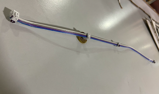
Once the codees were uploaded, I tried working with it and it was working.
Files
The Master code can be downloaded from here
The Bunny 1 code can be downloaded from here
The bunny 2 code can be downloaded from here
You can download the schematic file and the board file here.