Week 7
Computer Controlled Machining
For this week's individual assignment we had to make something big using the CNC machine. The goal was to design, mill and then assemble the pieces. For this week's group assignment we had to test runout, alignment, speeds, feeds, and tool paths of our CNC machine.
A CNC machine is a motorized maneuverable tool and often a motorized maneuverable platform, which are both controlled by a computer, according to specific input instructions. Instructions are delivered to a CNC machine in the form of a sequential program of machine control instructions such as G-code and M-code, then executed. The program can be written by a person or, far more often, generated by graphical computer-aided design (CAD) software and/or computer aided manufacturing (CAM) software. In the case of 3D printers, the part to be printed is "sliced", before the instructions (or the program) is generated. 3D printers also use G-Code.
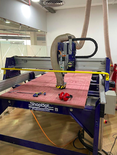
In our lab at Kochi, we have the Shopbot. Shopbot is a 3 axis machine the Z axis is perpendicular to the bed. The X and Y axis are the length and the breadth of the machine respectively.To have a rigid supporting layer on the bottom of the workpiece we will place an additional piece of plywood above the bed called sacrificing layer. The sacrificing layer also protect the millig bit from damage by avoiding unwanted intereference with the metal body. It can be used to cut timber, plywood, soft aluminum etc and has a bed size of 4x8 feet. She shopbot also has a dust collector that sucks in all the dusk while cutting. For reference, you can use the beginner's guide to using the shopbot . It is really helpful.
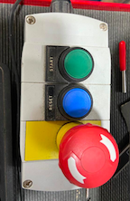
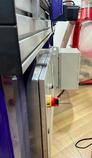
The shop bot has a few emergency switches to be used to turn the machine off at times of need.
Individual Assignment
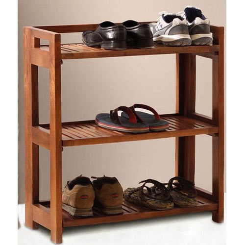
For my individual assignment, I wanted to make a simple and something I can use. So I decided to make a shoe rack and table top without using any nails or screws. I started by sketching a simple design on my book, while I searched online a bit in parallel
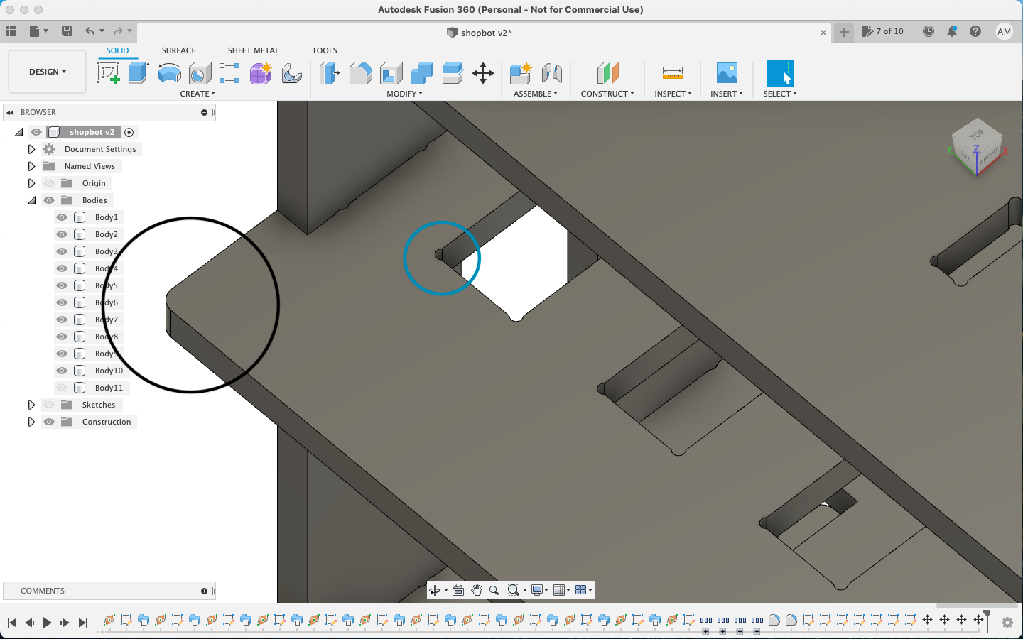
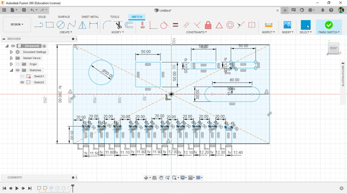
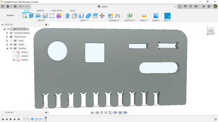
I then went ahead and designed it on Autodesk Fusion 360. The design was simple and stable and used parametrics everywhere needed. Once the design was done, I had to add a few things additional, like adding dog bones, fillets etc.

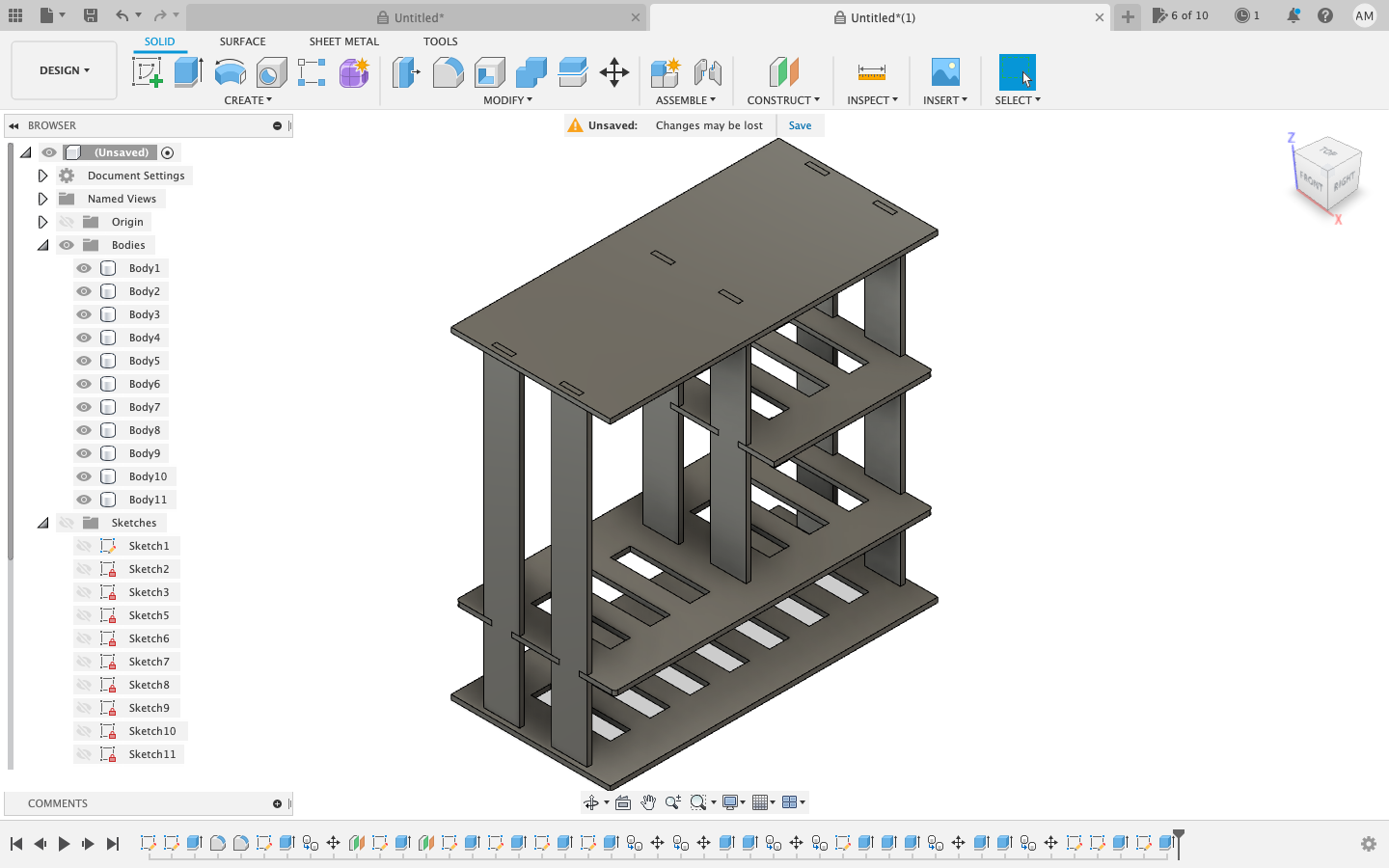
Adding dog bones manually is a bit of work. So I installed the Add In for Dogbones and then added it to Fusion and used it for adding dog bones. This was easy. This is the link to the tutorial to use it.
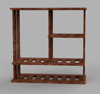
When the dog bones were added and all changes were made, I rendered the image and cut it using laser to see if everything is perfect. The laser cut was done perfectly and it fit correctly.
You can download the CAD file from here
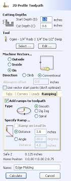
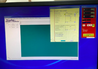
After the design was done and completed, I arranged the individual components on the sheet so that I can cut it. I uploaded the design file to the computer connected to the Shopbot. After rearranging the components again allowing screwing space, etc, I selected the mill, edited tabs, added ramps and all other details and generated the G Codes using VCarve.
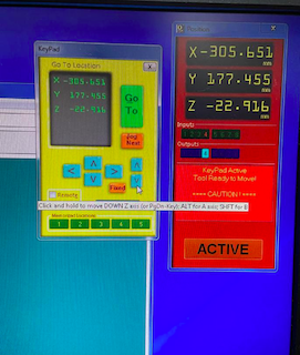
The tool path can be easily set up by just entering the details and setting up some parameter.
Shown below is the gcode for the cut.
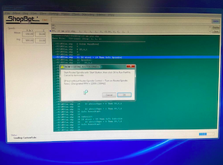
VCarve Pro provides a powerful but intuitive software solution for creating and cutting parts on a CNC Router. VCarve Pro gives you the power to produce complex 2D patterns with profile, pocket, drill and inlay toolpaths, plus gives you the ability to create designs with v-carving textures as well as import and machine unlimited Vectric 3D clipart or single model files. The ‘Pro’ edition gives you unlimited job and toolpath size, true shape nesting & job set-up sheets, ideally suited to a production environment.
There are some general safety measures to follow before using the machine.
General Safety and Precautions
-This safety summary contains general safety warnings that should be understood during operation of this machine. Failure to observe these precautions could result in injury.
-Learn and understand safe use of the machine. Do not allow untrained individuals to operate the machine without supervision. Be aware of the location of the Emer- gency Stop switches at all times.
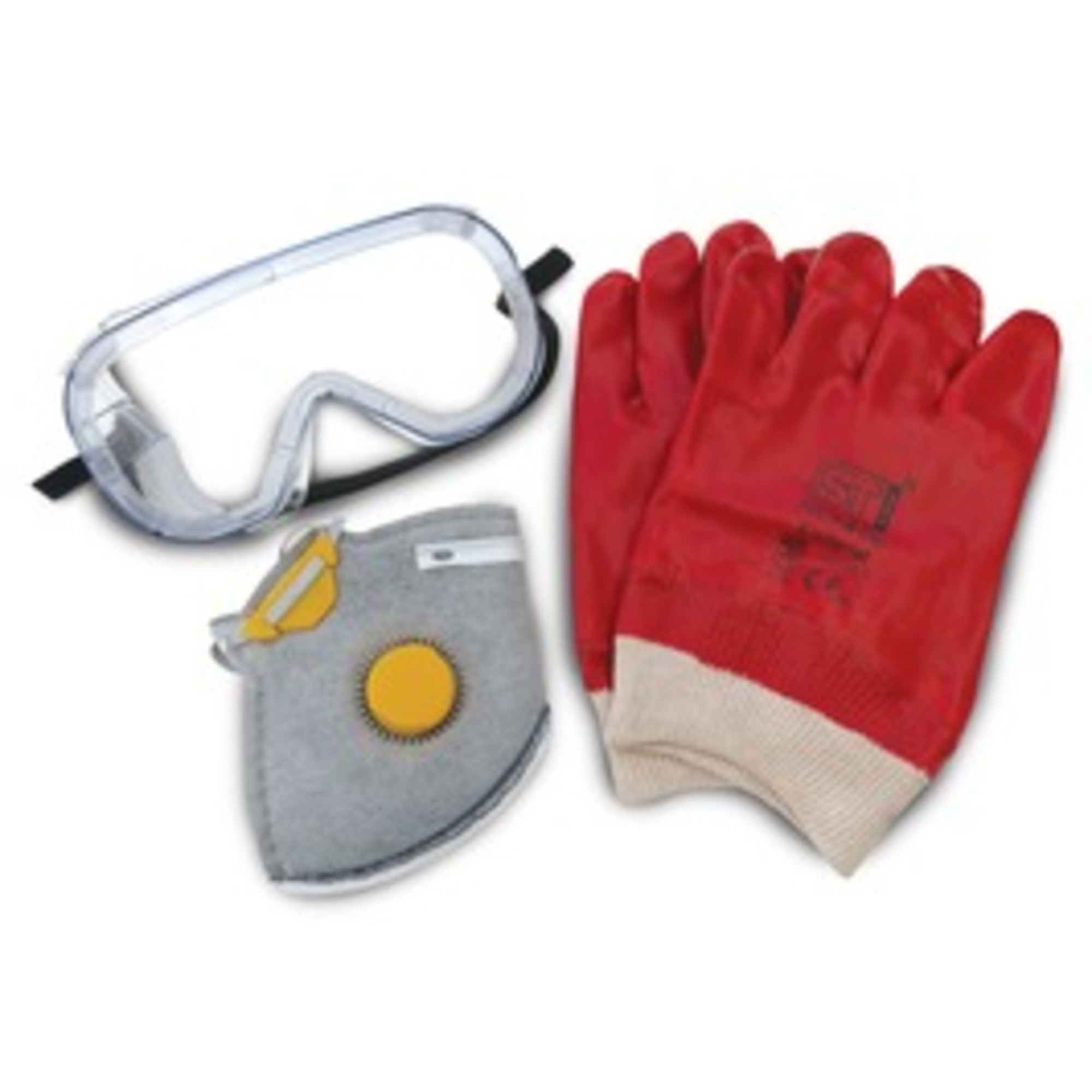
-Eye and ear protection MUST be worn by the machine operator as well as any bystanders or observers. Flying sawdust, material chips, and other debris can cause serious eye injury.
-Wear closed-toe shoes at all times.
-Make sure that your material is properly secured before cutting, and be aware of any small parts that may come loose after being cut. If a small part catches the edge of a spinning bit, it can be thrown forcefully in any direction, causing injury or damage.
-Never place your hands on the rails of the ShopBot. Be aware that the machine may move unexpectedly in any direction, which can cause serious injury if your hands are in the path of movement.
-Never wear gloves while operating the machine. As with any power tool, a glove can get caught in moving or spinning parts and pull your hand into the machinery.
-Never leave a machine running and unattended. Understand that a spinning tool generates friction and heat, creating a risk of fire. This risk is minimized by using correct chip load, using sharp bits, and by always double-checking your files before cutting. Be prepared to pause or stop the cut if something seems incorrect or unsafe.
-Keep a working fire extinguisher within reach of the machine, for the reasons listed above.
I used this manual to set up the machine and learn more about it.
I used plywood with 8*4 ft and 18 mm thickness.
Cost fot the same would be around $65.
Then I aligned the stock almost parallel to the axis and started to screw down the corners of the stock using a 3/4" drywall and steel screws with the help of codeless drill.
I initially made a mistake of not cleaning the bed first, which showed a problem with the bed level. I had to take the wood out and clean all over again before starting the cut.
Once everything was set up, I started the cut, it took around 1 and a half hours to finish the cut.
As the cut was done, I had to sand it and assemble it. Sanding and filing were to be done to have a perfect fit in due to imperfections in the plywood.
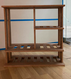
Once the sanding was done, I started assembling the parts and press fits to build my shoe rack. This was a bit tough but was worth the effort, after a few minutes, the shoe rack was completed! This is how the final product looked like compared to the rendered image!
Group Assignment
This week We need a test runout, alignment, speeds, feeds, and toolpaths for our machine by part of our assignment. So for testing some parameters in shopbot, we have designed a structure in Fusion 360.
Once the cutting was done, we had the plywood filed and sanded the edges.
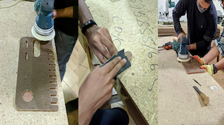
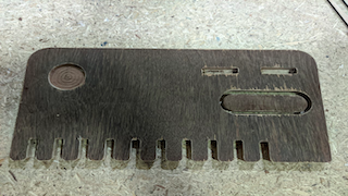
This was our group assignment to find the press fit dimension for the 12mm and 18 mm plywood .So we cut slots from 18.60 to 17.80 in steps of 0.1mm and for 12mm from 11.70 to 12.50 in steeps of 0.1 mm. We found out that the right press fits comes somewhere near 18.6 mm and 12.4 mm. The material thickness does vary a bit with temperature, moisture etc.
Files
You can download the f3d file from here
You can download the .stl file from here
You can download the .dxf files from here
You can download the .dxf files from here
You can download the .dxf files from here
You can download the .dxf files from here