Group
1. Test the design rules for your 3D printer(s)
Individual
1. Design and 3D print an object (small, few cm3, limited by printer time) that could not be made subtractively
2. 3D scan an object (and optionally print it)
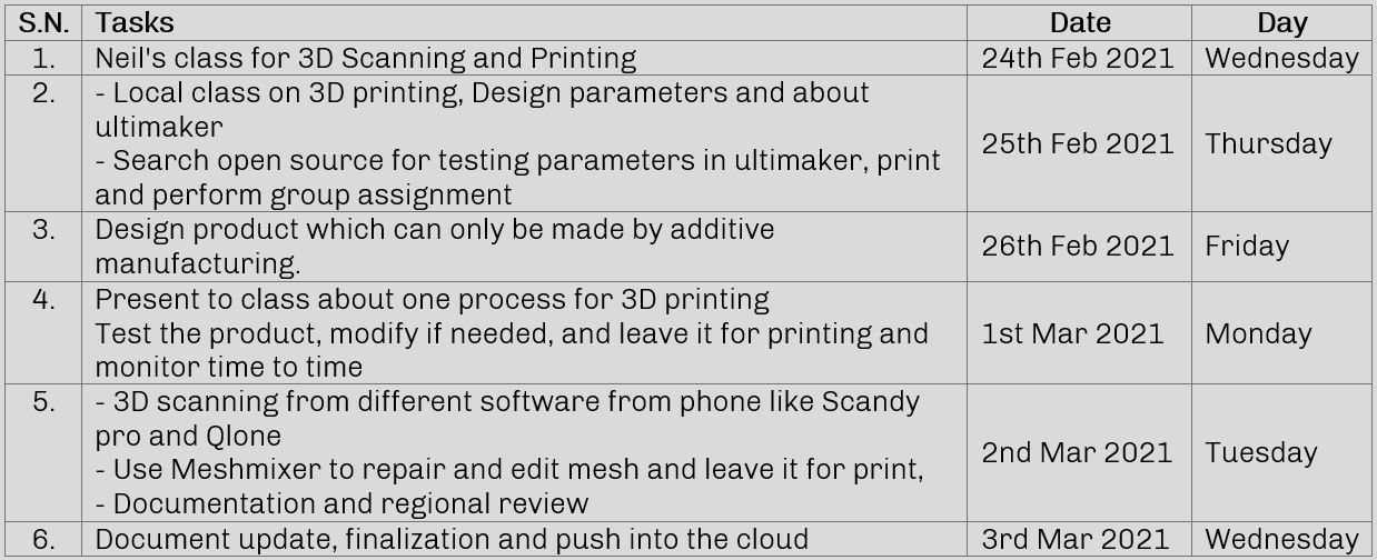
Plan for the week
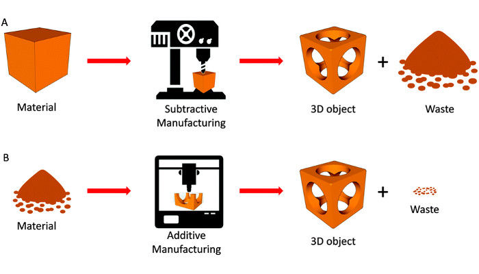
3D Scanning and printing, an interesting week where we can fabricate our design and also 3D scan the real object. Back in Nepal, I used Upbox+ from tiertime for printing 3D objects using filaments like PLA, ABS and PETG. 3D printer, as the name suggests, is a printer, which prints a 3D object as per our 3D file. 3D printing is an additive manufacturing process where the physical object is created by adding material layer by layer from he digital file.
(Source: www.3dnatives.com)
3D printing works layer by layer to form a shape. If you see the image below, differently trimmed paper layed one over another forms the shape for thumb cut in 3D. Similar to this, 3D printing also works on similar principal of adding layer by layer to form a complete physical 3D object.
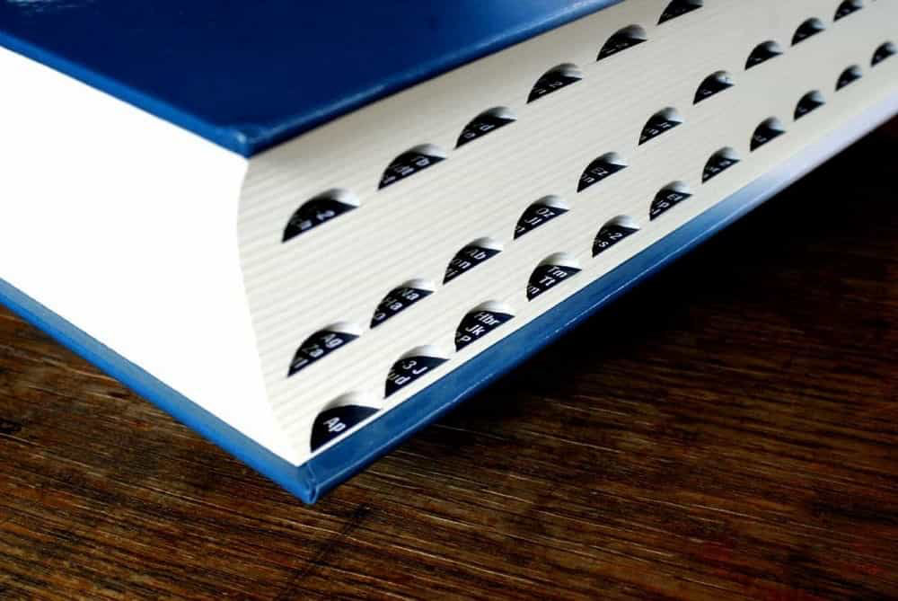
(Source: http://www.pilatross.com/)
As other digital manufacturing process, this also requires a digital file to operate. We should have a 3D file designed in any software in stl format. After we have the stl file we process it in a slicer which basically slices the 3D in different layers according to our input. A G-code then exported from the slicer to the printer which include printer settings and tool path based on which the 3D printer operates.
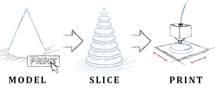
(Source: http://www.pilatross.com/)
3D printers have a head which might be extruding plastic or pointing laser or UV or any depending upon the application of printer. They move that head in a 3 dimensional space for making the 3D product. We can categorize printer by mainly two ways. One is according to the technology and another kinematics or the mechanism behind the movement.
Types of 3D printing Technology
I tried to differentiate it by following way.
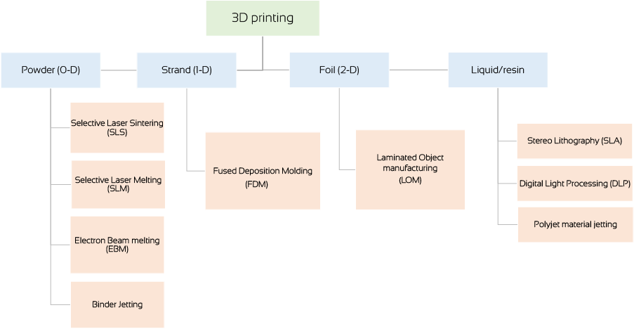
Now, Let me explain about 3 types which are most commonly used.
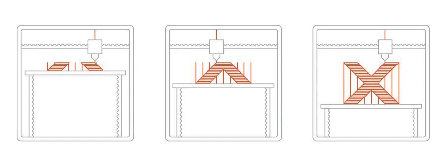
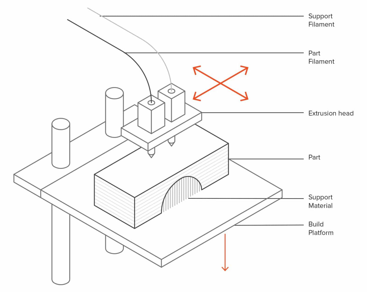
Fused Deposition Modeling (FDM)
Fused Deposition Modeling printer is the most commonly available printer in the market. We will be using this type of printer in our Kochi lab to print our designs. The way it works is that a spool of filament is loaded into the 3D printer and fed through to a printer nozzle in the extrusion head. The printer nozzle is then heated to the desired temperature, and the extrusion motor pushes the filament through the heated nozzle, causing it to melt.The printer then moves the extrusion head along with specified coordinates, laying down the molten material onto the build plate where it cools down and solidifies. Once one layer is complete, the printer prints the another layer above the previous one and retpeating the addition of layer upon layer, the 3D object is printed.
Applications: Protyping, DIY, product design, Electrical housings; Form and fit testings; Jigs and fixtures; Investment casting patterns
Pros: Compararively cheap, Decent surface finish, Full color and multi-material available
Cons: Brittle, barely sustainable for functional parts, high print time
(Source: http://www.all3dp.com/)
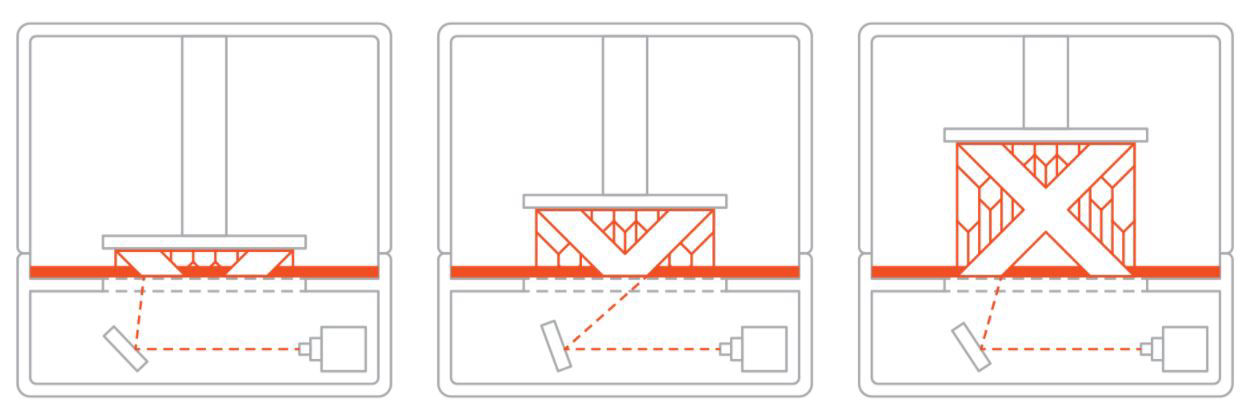
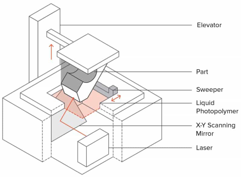
Stereolithography (SLA)
Stereolithography is the world’s first 3D printing technology which invented by Chuck Hull in 1986. Vat Polymerization is a 3D printing process where a light source selectively cures a photo-polymer resin in a vat (container). An SLA printer uses mirrors, known as galvanometers or galvos, with one positioned on the X-axis and another on the Y-axis. These galvos rapidly aim a laser beam across a vat of resin, selectively curing and solidifying a cross-section of the object inside this building area, building it up layer by layer. SLA printers excels at producing parts with high levels of detail, smooth surface finishes, and tight tolerances. The quality surface finishes on SLA parts, not only look nice, but can aid in the part’s function—testing the fit of an assembly, for example. It is widely used in medical field like dentistry. They use Photopolymer resin (Standard, Castable, Transparent, High Temperature) at the material.
Applications: Injection mold-like polymer prototypes; Jewelry (investment casting); Dental applications; Hearing aids
Pros: Smooth surface finish; Fine feature details
Cons: Time onsuming process, supports needed
(Source: http://www.all3dp.com/)
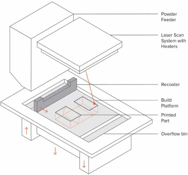
Selective Laser Sintering (SLS)
Selective Laser Sintering process works on the sintering principle, which means heating the powder just below its melting temperature to fuse it. In SLS, a laser selectively sinters the particles of a polymer powder, fusing them together and building a part layer-by-layer. The materials used in SLS are thermoplastic polymers that come in a granular form. SLS 3D Printing is used for both prototyping of functional polymer components and for small production runs, as it offers a very high design freedom, high accuracy and produces parts with good and consistent mechanical properties, unlike FDM or SLA.
In SLA 3D printing, first, a bin of polymer powder is heated to a temperature just below the polymer’s melting point. Next, a recoating blade or wiper deposits a very thin layer of the powdered material — typically 0.1 mm thick — onto a build platform.Then a CO2 laser beam then begins to scan the surface. The laser will selectively sinter the powder and solidify a cross-section of the object. Just like SLA, the laser is focused on the correct location by a pair of galvos. When the entire cross-section is scanned, the build platform will move down one layer thickness in height. The recoating blade deposits a fresh layer of powder on top of the recently scanned layer, and the laser will sinter the next cross-section of the object onto the previously solidified cross-sections. These steps are repeated until all objects are entirely manufactured.
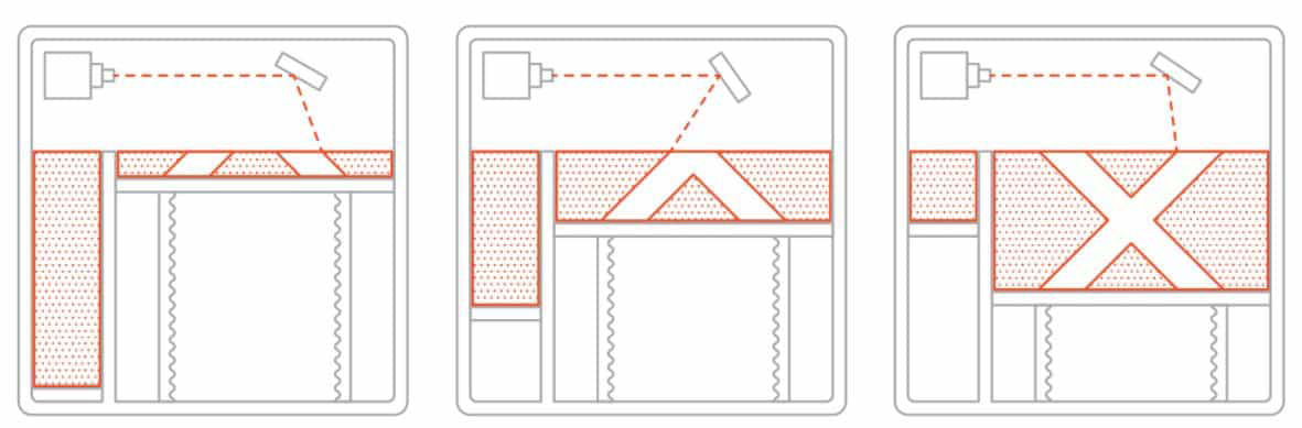
(Source: http://www.all3dp.com/)
3D Printers Kinematics
Most common FDM printers use cartesian kinematics but there are other mechanisms as well on which head is moved. They are Cartesian, Delta, Polar and 3D printers with robotic arms. The Printer we are using, Ultimaker 2+ also is a FDM printer which uses Core XY, cartesian kinematics. To know more about the movement please follow this link
Click here to know more about different kinematics, their advantages and disadvantages.
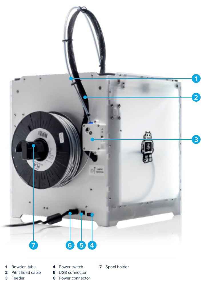
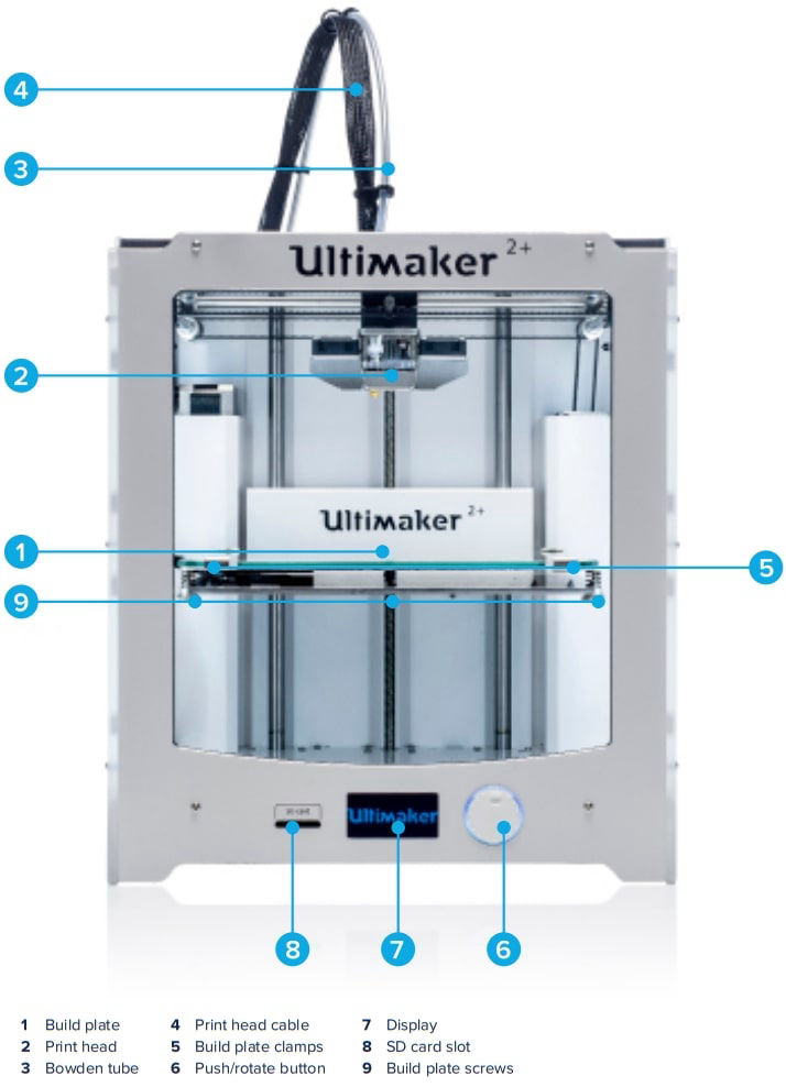
You can download the manual here to know more about the Ultimaker 2+

You can get more knowledge about these print settings in Cura from this link.
There are some tips and tricks for the FDM 3D printing. According to your printer there are certain capabilities of your printer which you can use in your design to be more effecient in time, material usage and quality.
You can refer this document to know about tips and tricks in detail.
Group Assignment
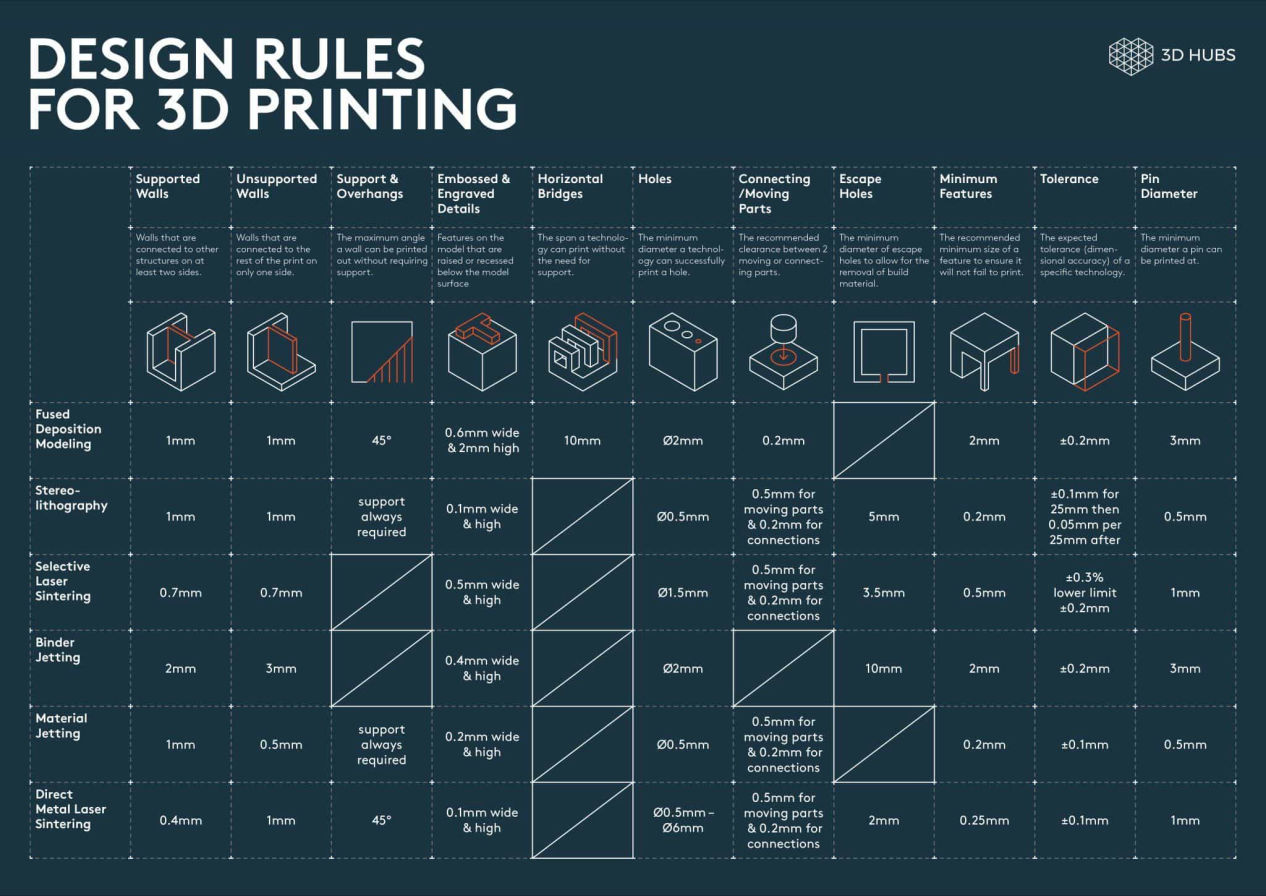
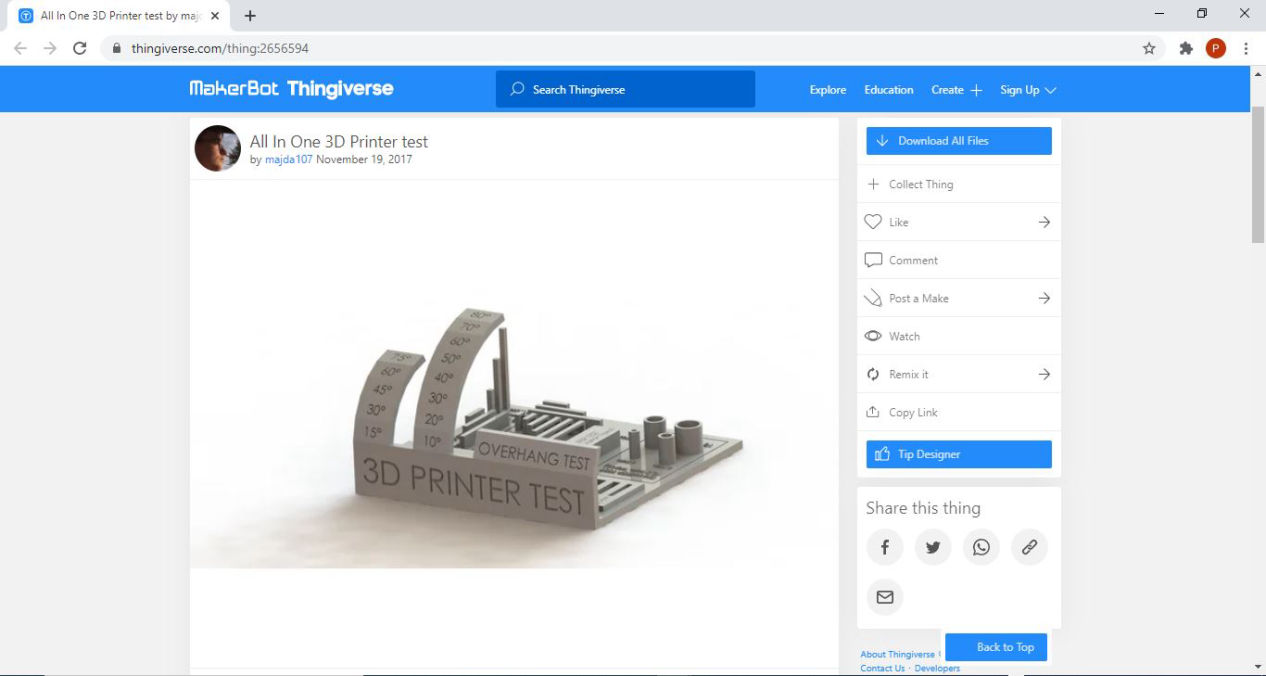
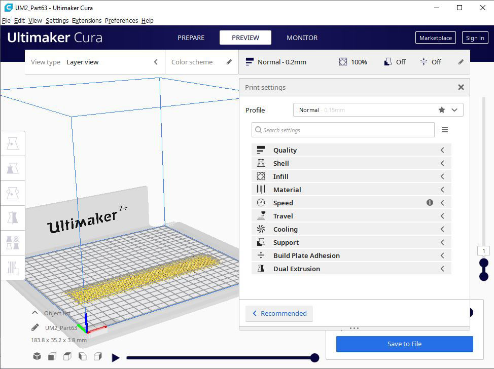
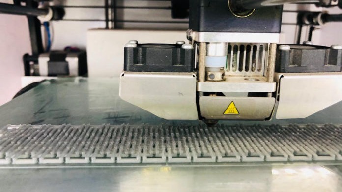
Our group assignment was to test the design rules for our 3D printer, Ultimaker 2+. Then we began our search in opensource platforms like, thingiverse, grabcad, cults3D etc to find out is there is any 3D which we can use to test out printer. We came out with different models and selected one for testing our 3D printer.
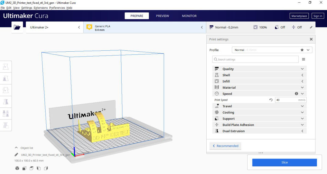
- Layer Height: 0.2mm
- Shell thickness: wall= 0.7mm,
Top/bottom =0.75mm
- Infill: 20%
- Material: Generic PLA
- Speed: 60mm/s
- Travel: Retraction checked
- Cooling: 100%
- Support: None
- Bed plate adhesion: Brim
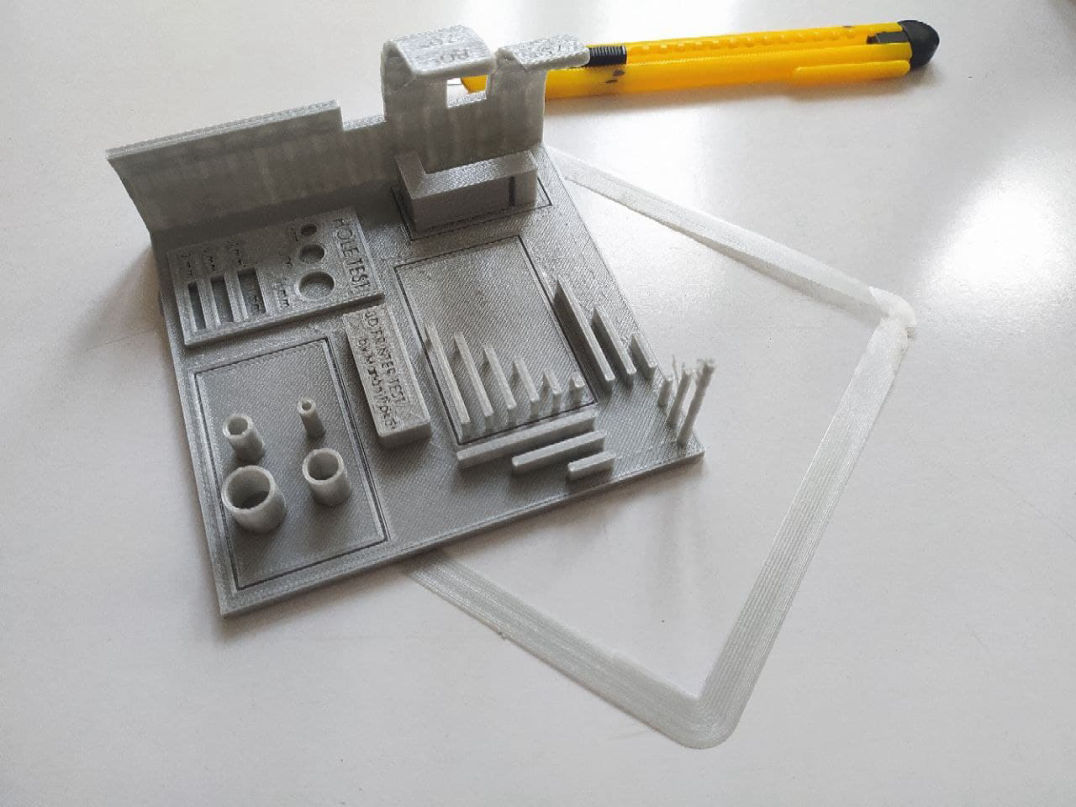
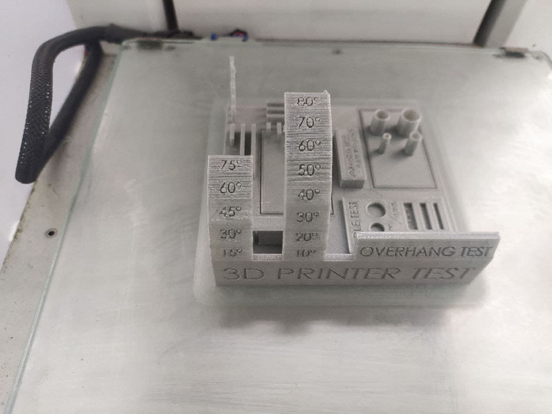
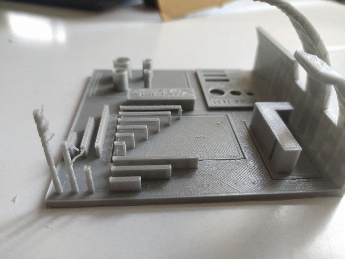
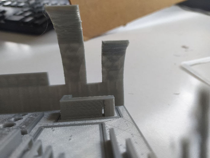
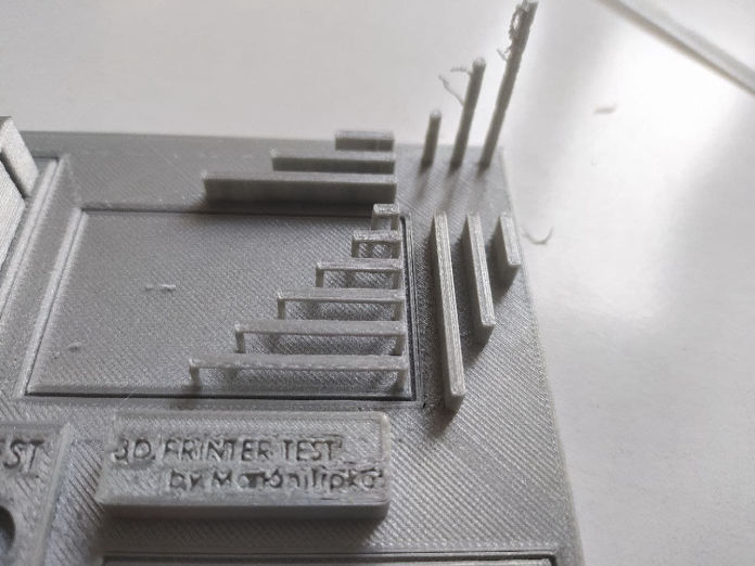
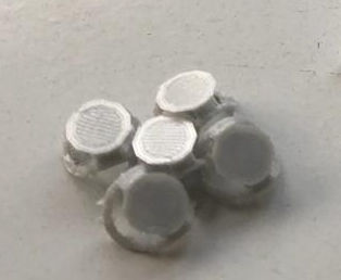
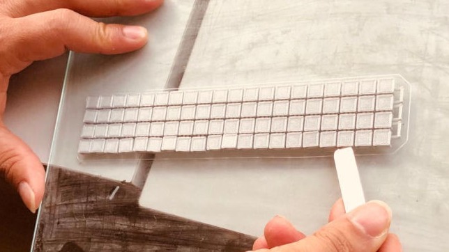
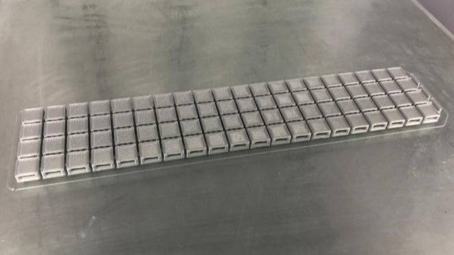
Following were the observations:
These capabilities and deviations should be accounted in the design to reduce time, material usage and quality of the print.
Individual project
I had used 3D printer for printing some of projects as shown below:
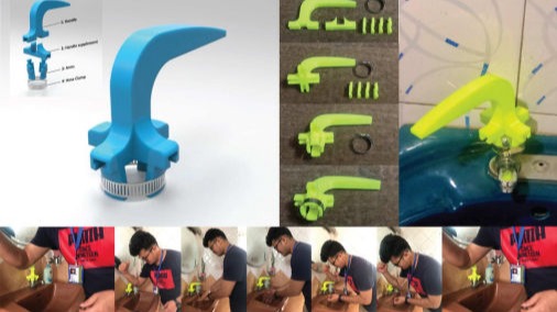
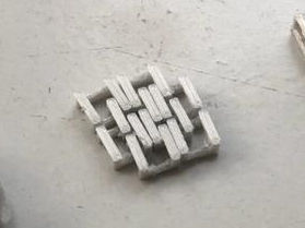
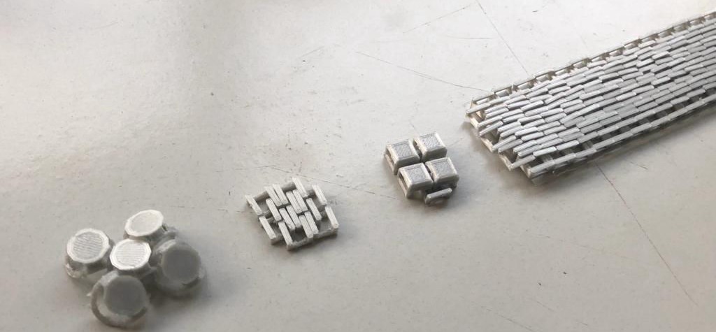
For this weeks individual assignment, I tried to design a chain which have flex in all direction. I want to make it like a fibre like srtucture. Taking considerations of the overhang, I tried to make an interlocking design.
STEP 1: First I started with a simple wavy shave inside one another that chan build a chain and tested.
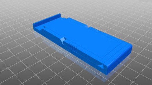
STEP 2: I tested the part. Though it was working, it was not as good as I had expected, it was due to the small diameter of the part. Also there was so loose. So i thought of using a bridge and make a similar shape but by using a rectangular shape. and designed another.
STEP 3: I printed a small part to test it. The flex was good and print quality was improved. Then I though of creating a skin above it so that the interlocks remain hidden inside. then tested a small size.
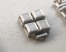
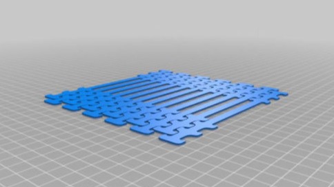
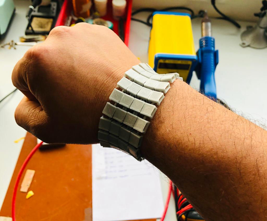
STEP 4: After all test was good, I used the Boolean command with parametric design to arrange it in array then added a cut to snap fit the outher side for making the bracelet.
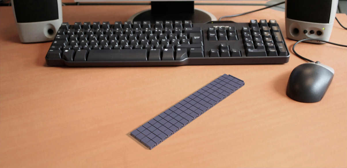
STEP 5: Then I exported the file in stl format to slice it with Cura.
Finally, the print was ready and the product after iteration was like the figure below.
3D Scanning
Application used: a. Qlone, b. Scandy pro
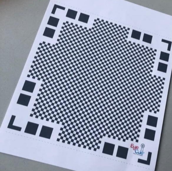
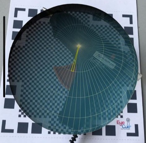
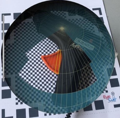
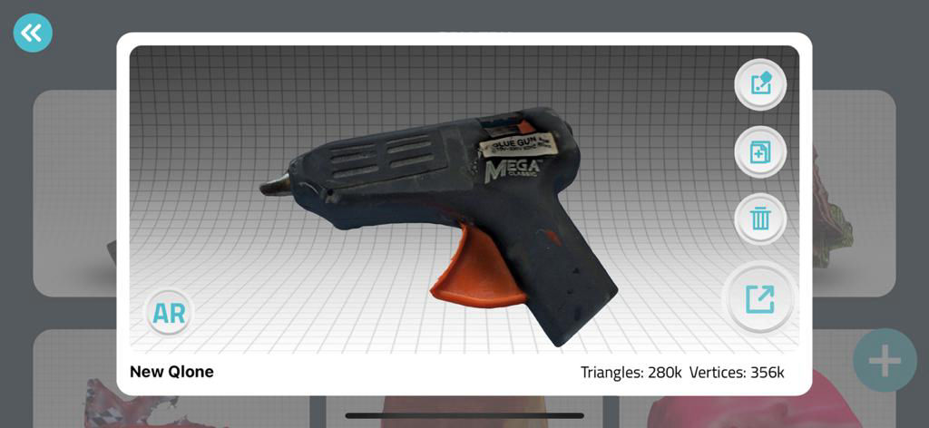
We will be using Artec 3D, a professional scanner for 3D scanning. Meanwhile I tried Qlone but was not free so could not export stl file from it. Qlone is a software which uses a reference sheet to locate the actual object to be scanned. It takes multiple pictures and use photogrammetry to create a 3D model from it. It use at least two or more image to locate a point in space and use it to make a 3D. Following process is used to scan an object from phone.
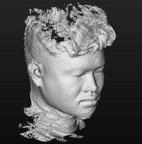
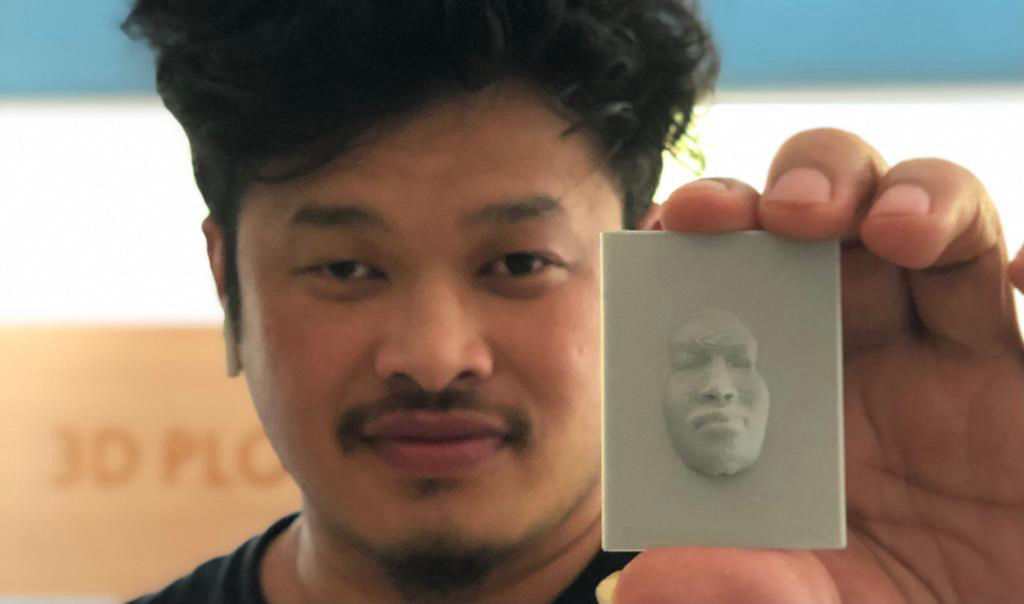
Then I used Scandy Pro, in which we can scan and export one file for free in every 24 hr. This software uses the front two cameras with the depth map that Apple's TrueDepth sensor provides to mesh the points together to create a 3D scan. you need to be in really good lighting and steady hands to scan.
To scan, after the app is installed, you need to move it steadily around your face so that the algorithm can refer consecutive frames. Since it takes multiple photos, your mobile is going to heat up very fast and battery will also drain fast. It makes very fine mesh for the scan you do.
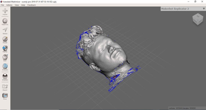
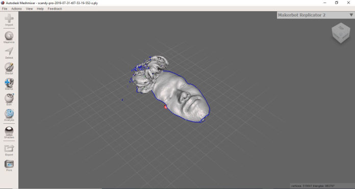
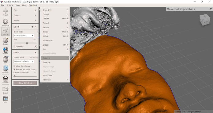
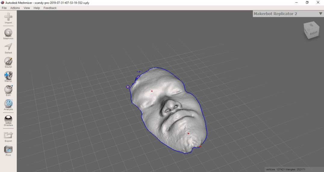
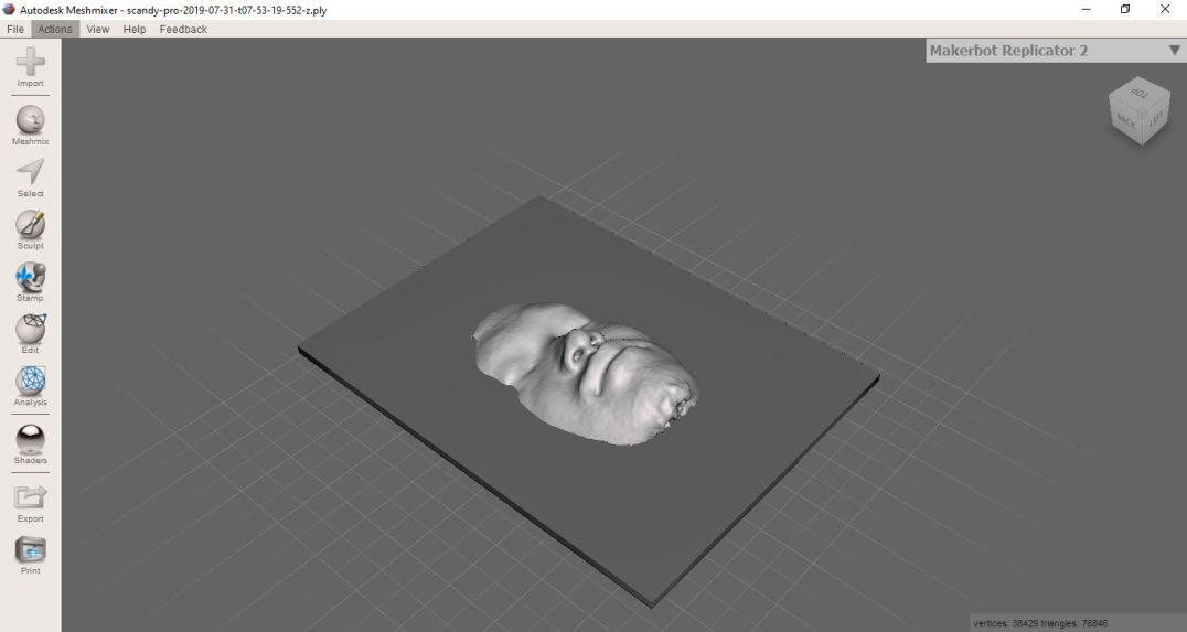
After the scanning was done I used mesh mixer to extract the surface i wanted.
This page was created with Mobirise