Group
1. Characterize your lasercutter's focus, power, speed, rate, kerf, joint clearance and types
Individual
1. Cut something on the vinylcutter
2. Design, lasercut, and document a parametric construction kit, accounting for the lasercutter kerf, which can be assembled in multiple ways, and for extra credit include elements that aren't flat
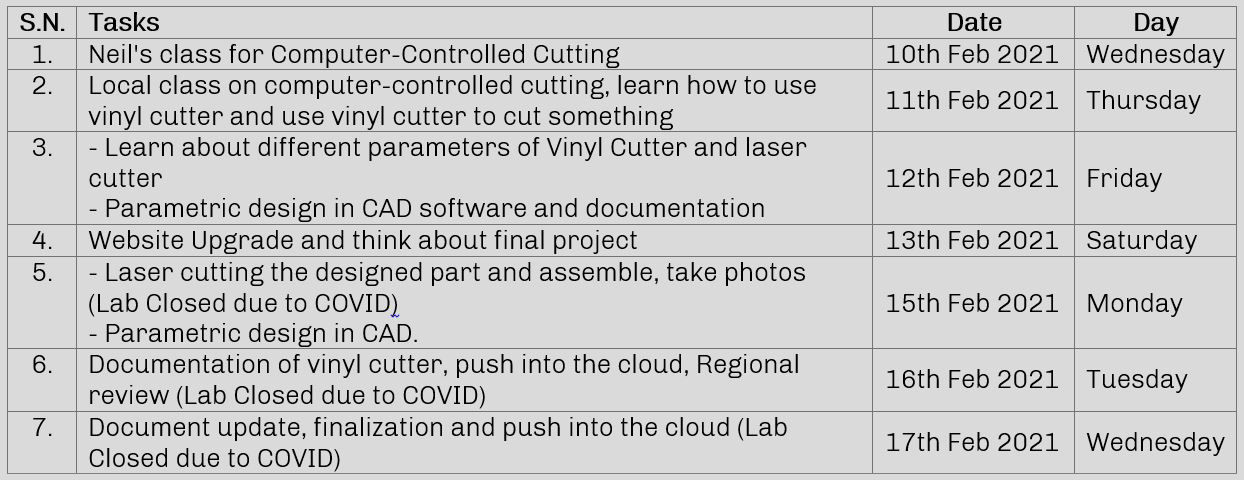
Plan for the week
This week is our computer controlled cutting week where we are creating compatile design files, knowing about the devices like laser machine and vinyl cutter, controlling them by communicating via Mods and controlling the parameters like cutting force,speed in case of vinyl cutter and kerf, speed, intensity in case of laser machine. Staring the week we began to work with vinyl cutter then to laser machine.
Working with Mods
Mods is software tool developed by MIT's Center for Bits and Atoms (CBA) to help build digital fabrication workflows in a modular way. It takes a design in one format, process through its algorithm consisting different modules calculating and analyzing the file and finally generate code that machine can understand and send it to the machine. Best part of it is that we can visualize all the process and know about the flow of the process. And secondly, it can be used for operating multiple digital fabrication devices like vinyl cutter, laser cutter and CNC mills in Fablab.
About the machine
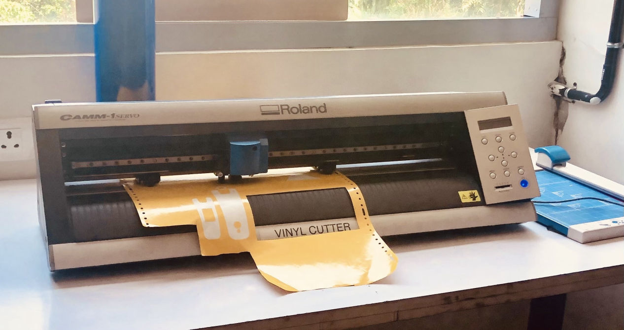
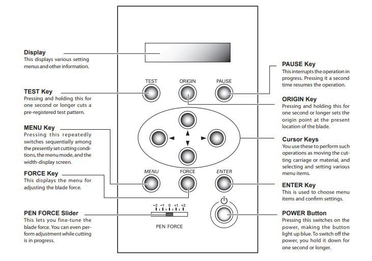
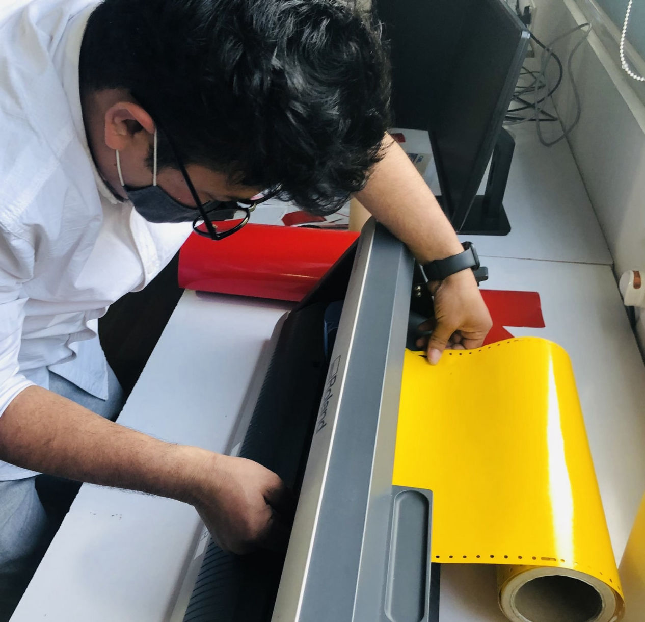
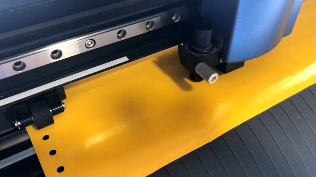
Vinyl cutter is a 2-Axis cutting machine which can move the fine point blade to perform a cut in a thin sheet of material like vinyl, paint mask, reflective vinyls, twill, heat transfer, circuit making material and sandblast material. We need to first choose the material we need to cut and the blade as well. For loading and unloading material there is a load/unload lever on the left side of the machine. Please refer the manual. Then, choosing the blade, you must consider the thickness of the material you are going to cut. There are normally blades with three angles 30, 45 and 60 degrees. Lesser angles are for lesser thickness and vice versa. Now while loading them please note that the protruded length of the blade is he sum of media portion and half of carrier portion as mentioned in the link mentioned above.
For the current cut, i used, 60 degrees blade with diameter 0.254mm, cutting speed of 2mm/s, and cutting force of 110gf.
Loading file and pushing to the Machine
1. Making a vector file: First, I downloaded an image to convert into vector which is used as an input to the vinyl cutter via Mods Then I used Adobe Illustrator to convert the raster file to vector file. Download here

2. Then on the computer, the folder where mods main file are saved, terminal is started from that folder using following code
bash start-server
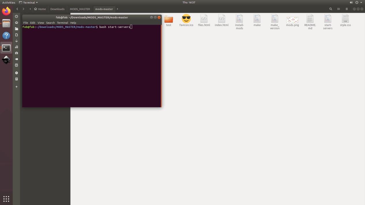
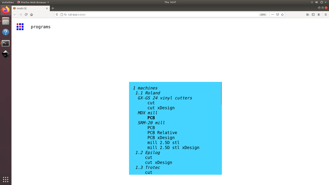
3. This will open up the landing page where you can select between different operations. Select cut under Roland GX-GS 24 vinyl cutter.
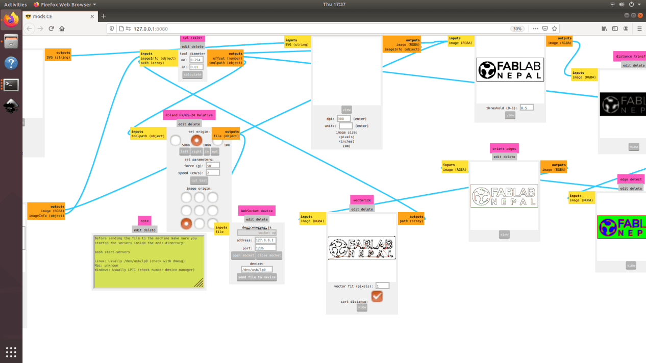
4. Now, you can either enter a svg file or a png file as an imput. I selected the png file. Enter the tool diamater and hit calculate. As soon as you hit calculate you can see all the process in the flow and final tool path can be seen.
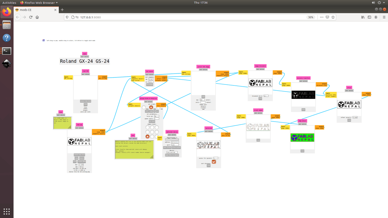
5. Next, check whether the tool path is ok or not. Some times, if the image is too small or if there is any image procesing problem, if tool path may not be as per our expectation so please make sure it is ok before starting the cut. Then select the cutting speed and the cutting force for the machine. Open the web socket and click on the "send file to device" which should start the cut.
Applying vinyl to the product
Now, after the vinyl is cut, remove the material and use the tweezers to remove the excess material leaving only text and apply the application tape to maintain the position of all the characters. Then affix the material together with the joined application tape to the target object.
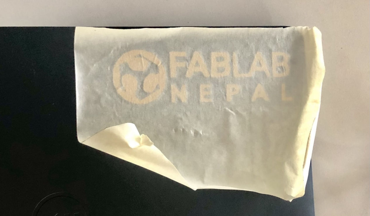
Now cautiously remove the application tape.
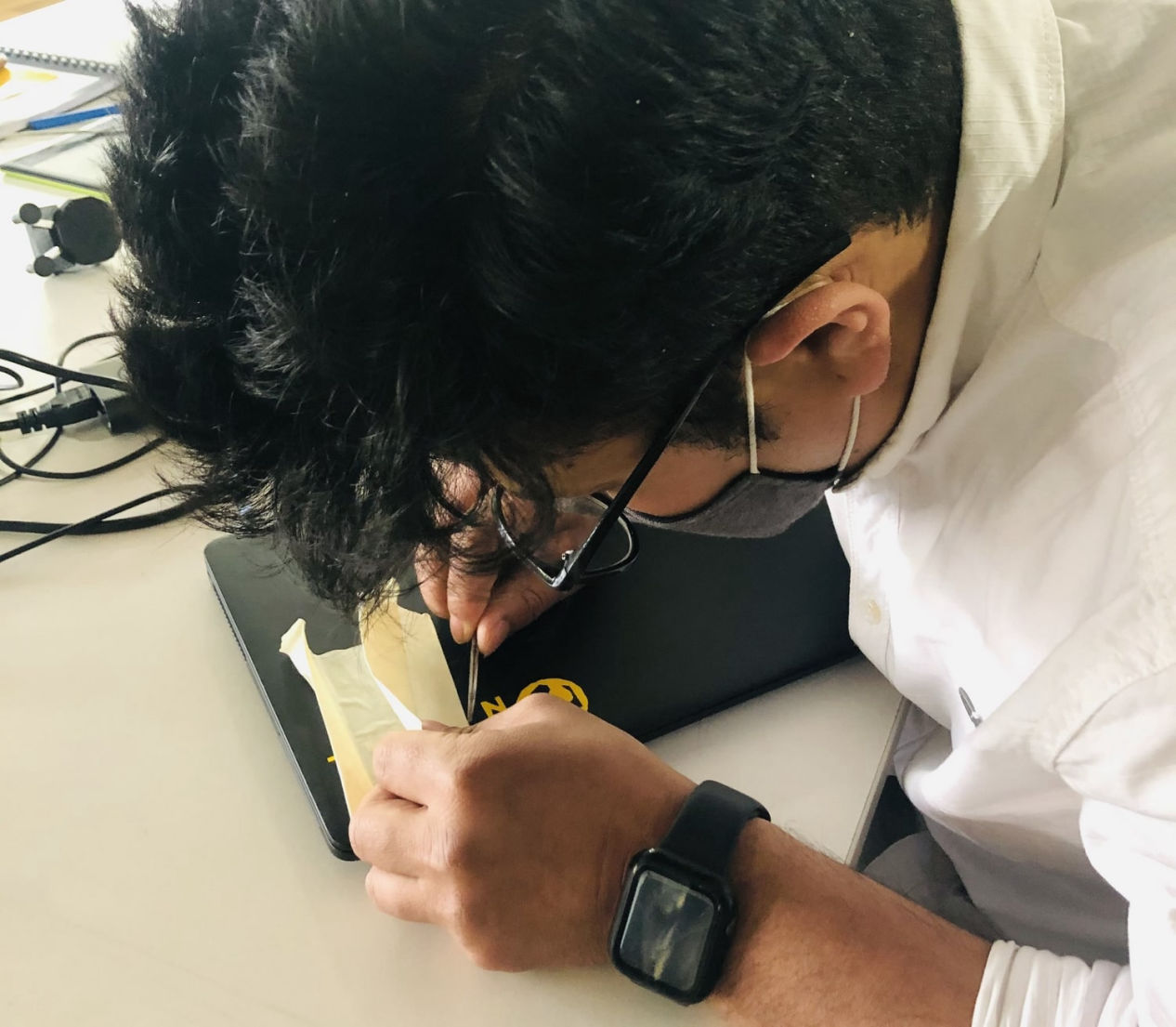
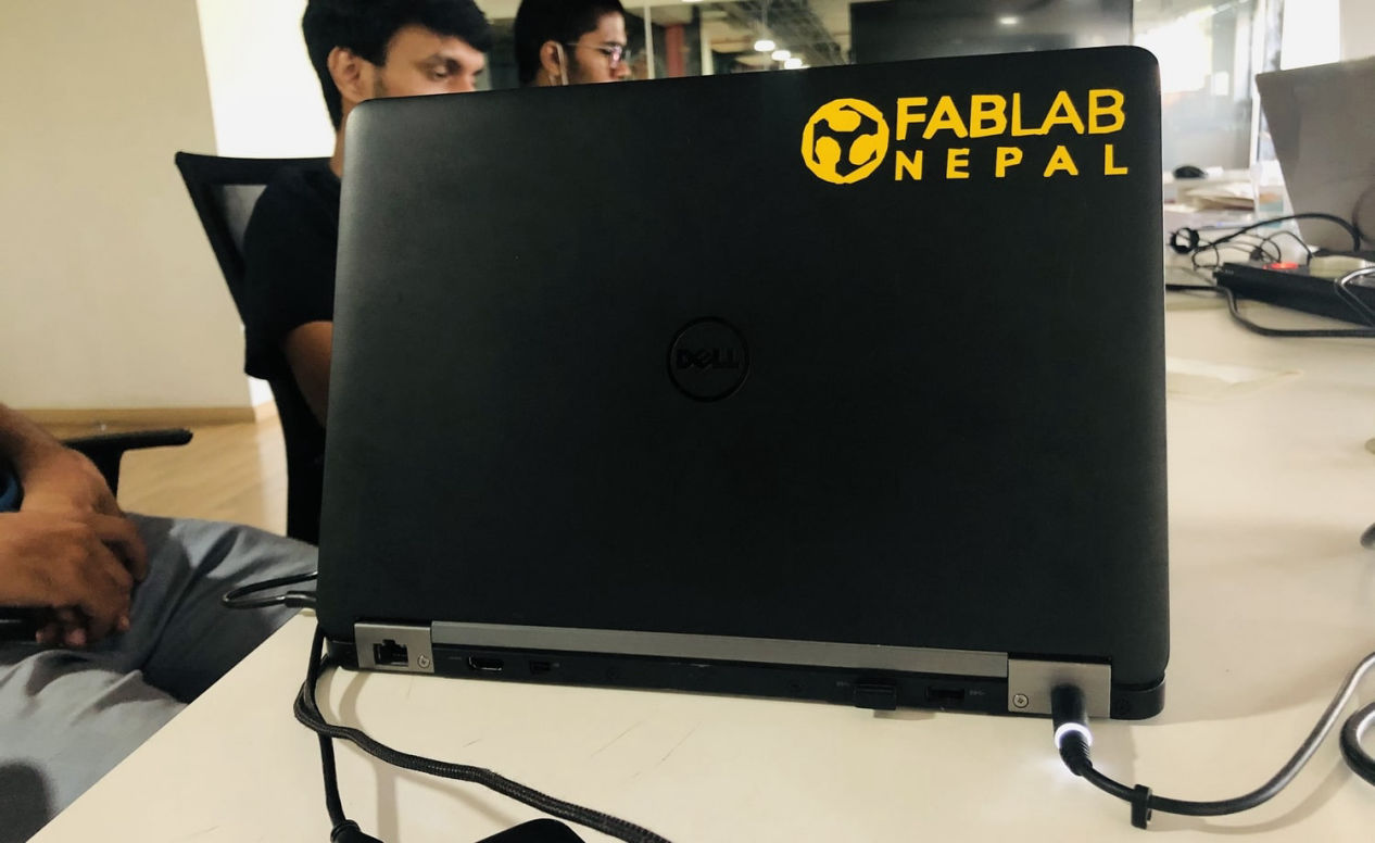
Finally the result for vinyl cutter
Parametric design is like a spreadsheet that is set up to make calculations; you choose which math function will be performed, input the different numbers, and your result depends on what those variables are. This is basically the parametric design process. Parametric design is a very useful tool to any designers. It lets you modify the final product based on the parameters you enter. It may be time consuming to do parametric design, but, once you do it, you know its value during modification or for alterations of your design.
CAD
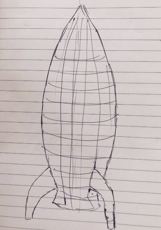
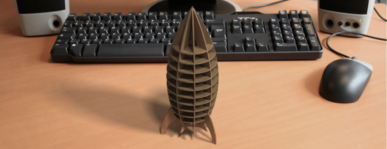
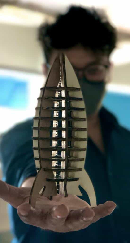
For the laser cutter, I was just thinking about the products that i could make. While showing other how to do parametric design in CATIA, my instructor asked why don't you design a rocket out of fun. And I thought, WHY NOT? Then I followed following process:
1. First I have to make a construction kit so first i thought of a platform for the rocket as a launcher
2. Then I tried the whole design of platform with rocket and first focused in platform at first.
Modular designed Platform
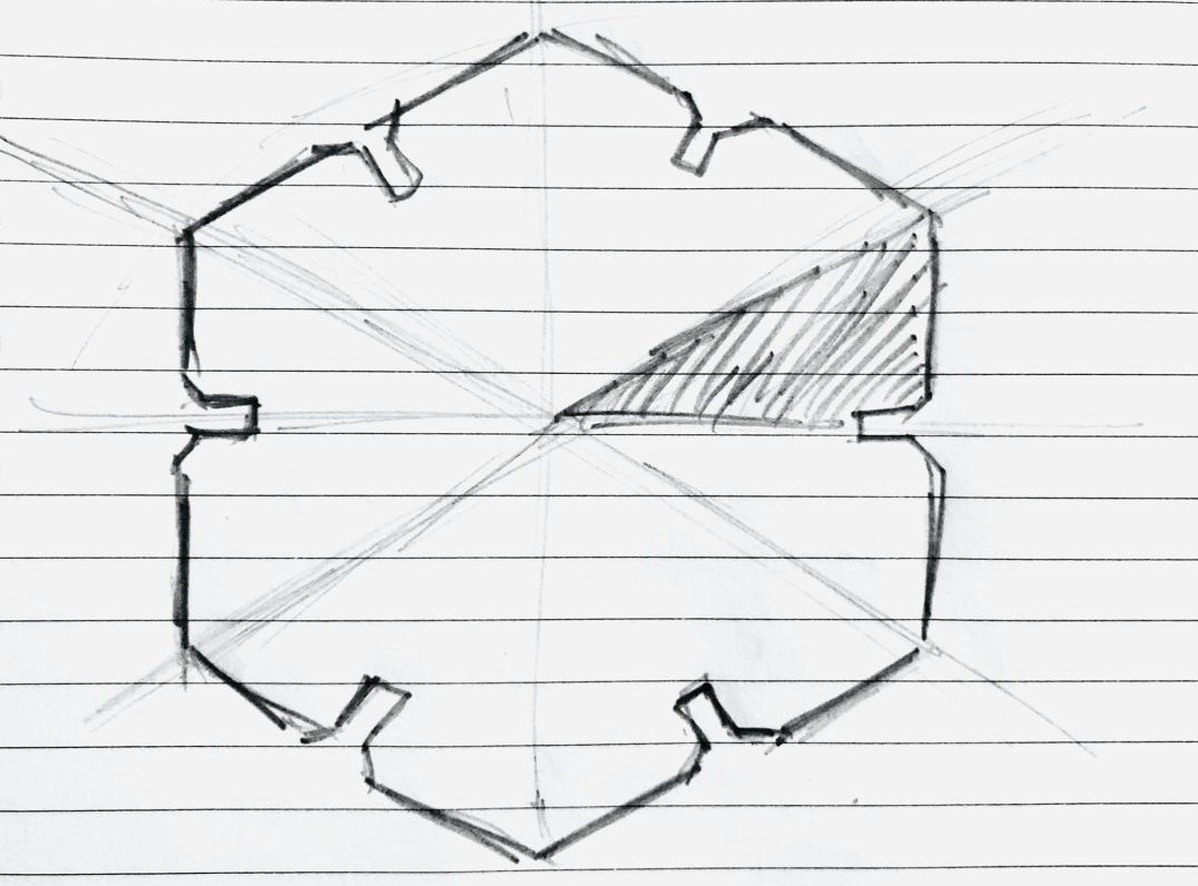
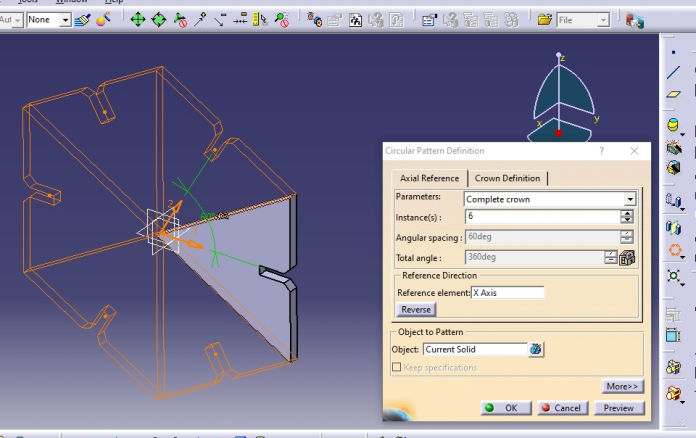
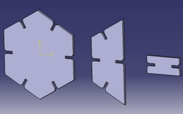
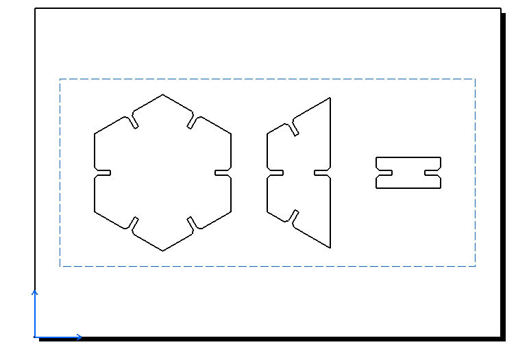
1. Designed modular platform for the rocket using 3 main shapes.
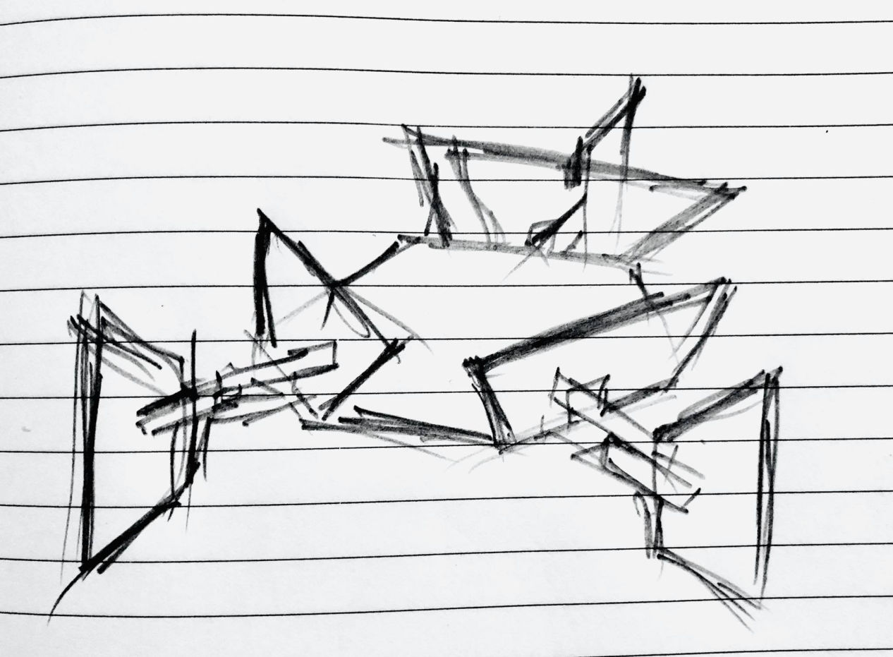
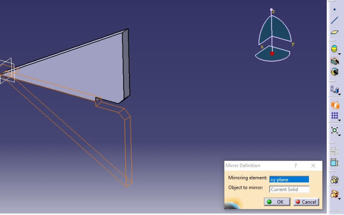
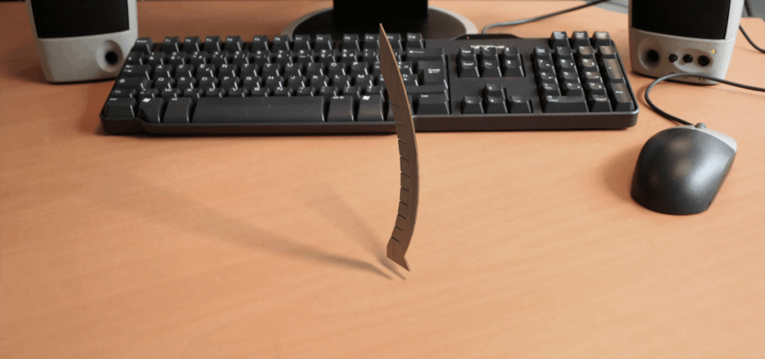
2. Separating the design only for the platform, first what I did and should be done while modeling as well as designing is finding the basic element of your design which can be a base element for mirror or boolean operation making the while body.
I will give you one example of what I have done.
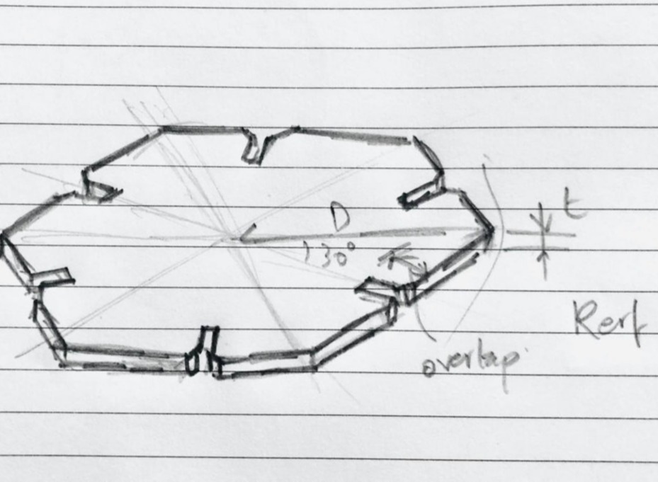
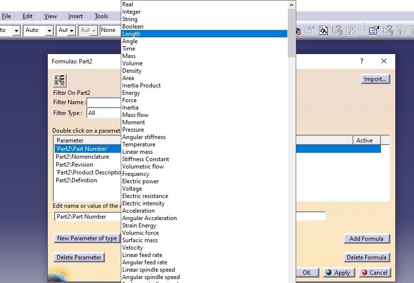
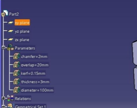
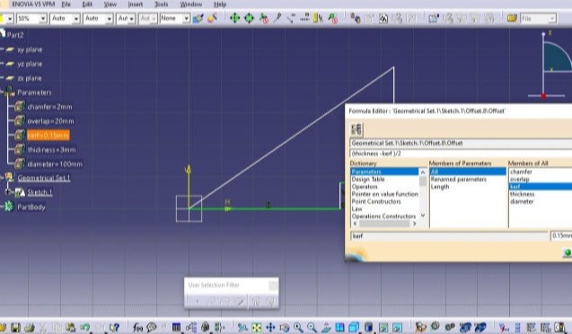
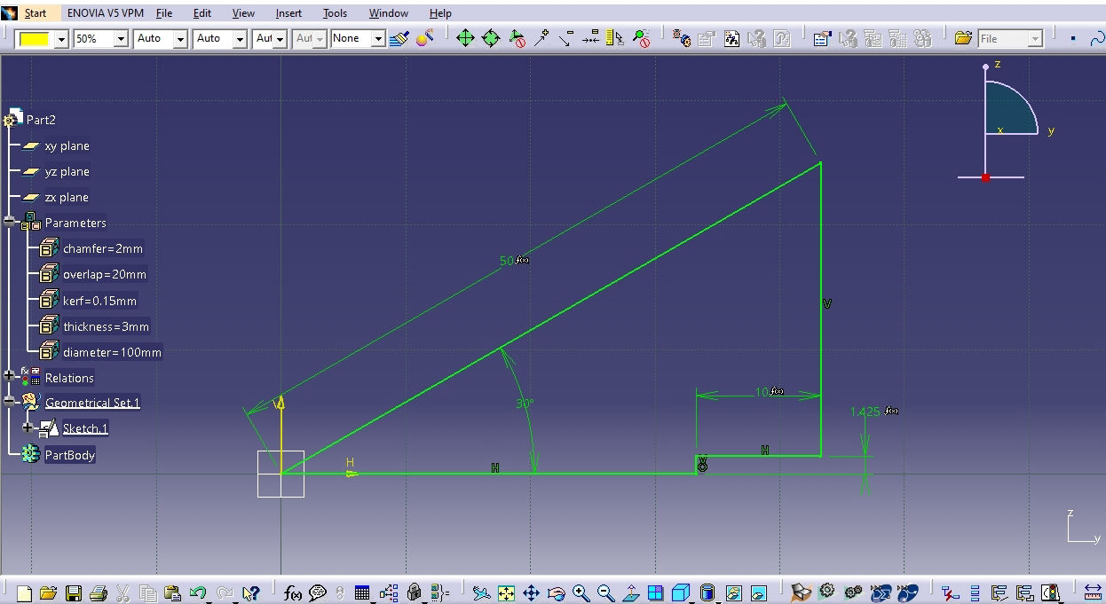
3. Then Time for deciding the parameters and the open CAD software. or me I have selected diameter, thickness, kerf, overlap and chamfer as parameters.
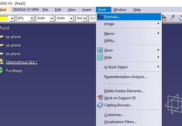
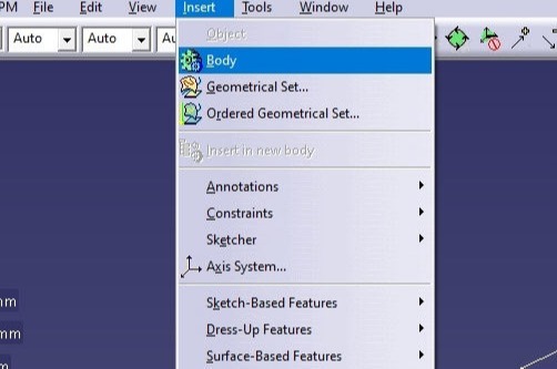
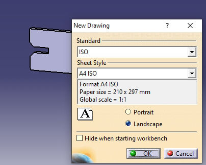
4. I am assuming that you have already installed CATIA V5 and know basic modeling skills in CATIA. Open CATIA V5, then File >> New >> Part
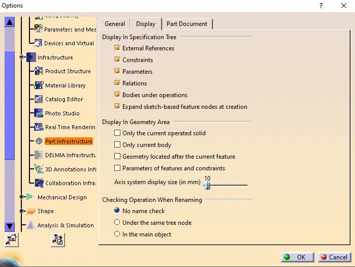
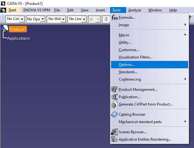
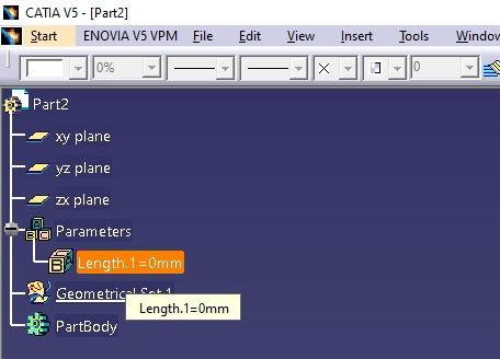
5. If you have not used parametric design previously in CATIA, your parameters and relations might be hidden so first you have to change settings to show on the tree. GoTo Tools >> Options >> Infrastructure >> Part Infrastructure, Then click on Display tab and check parameters and relations and hit OK.
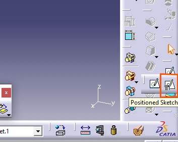
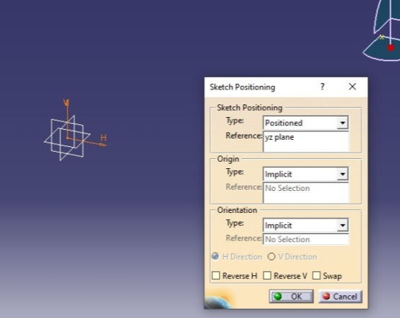
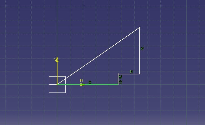
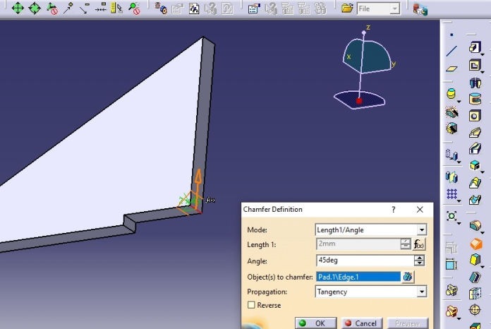
6. Now modeling begins. Please follow following process to complete model in CATIA
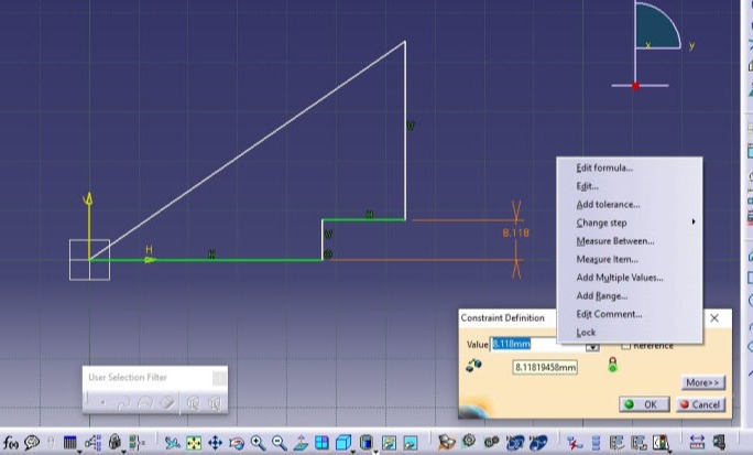
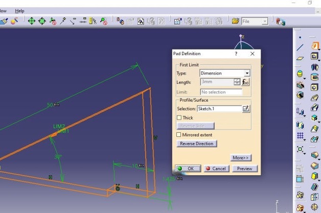
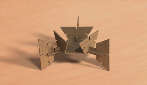
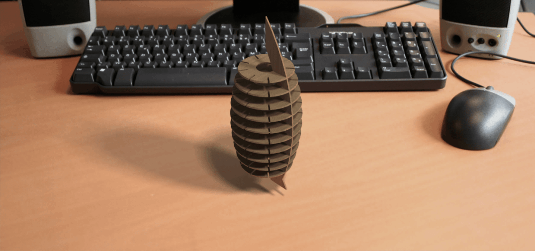
The Rendered image is as shown below.
Results after modeling
Download CAD file
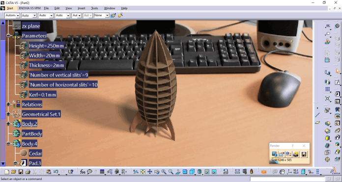
Height of the Rocket= 250 mm
Width of the section = 20 mm
Thickness= 2 mm
No. of vertical sections= 9
No. of horizontal sections= 10
kerf of the laser=0.1 mm
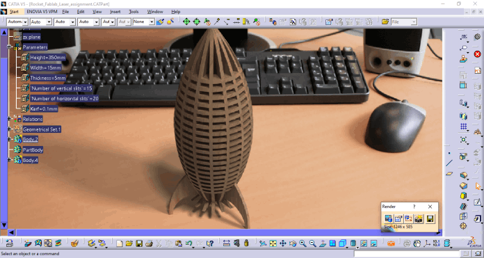
Height of the Rocket= 350 mm
Width of the section = 15 mm
Thickness= 5 mm
No. of vertical sections= 15
No. of horizontal sections= 20
kerf of the laser=0.1 mm
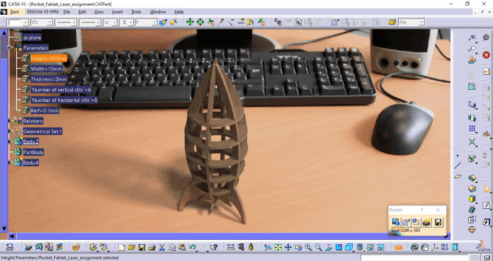
Height of the Rocket= 200 mm
Width of the section = 10 mm
Thickness= 3 mm
No. of vertical sections= 6
No. of horizontal sections= 5
kerf of the laser=0.1 mm
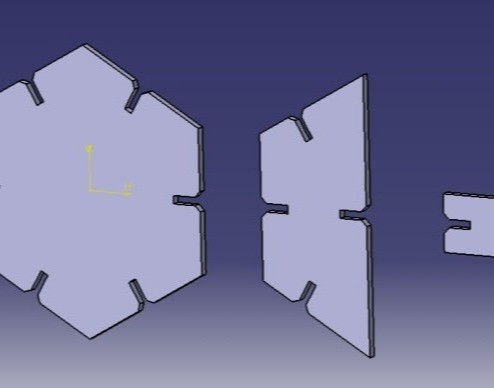
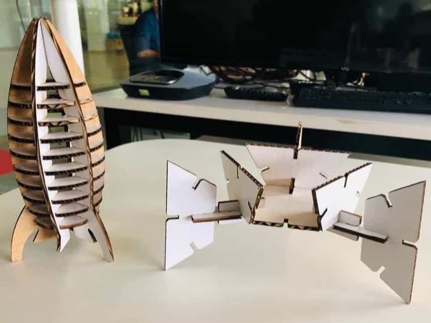
Modular platform
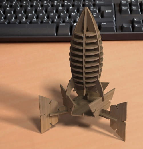
Both when set together should look like below.
Download CAD file
Laser Cutting
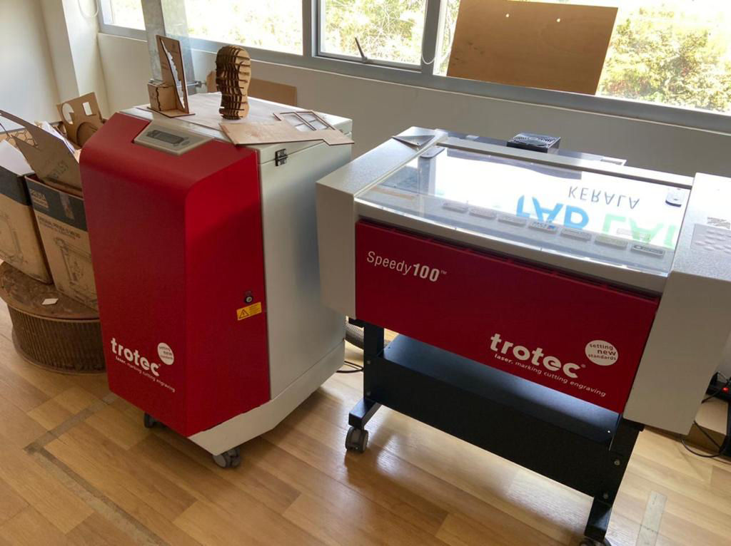
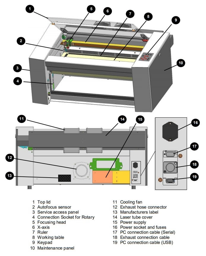
Laser cutting is one of the most used machine in Fablab. The one we are using is Trotec speedy 100. It is a machine with CO2 laser which can process wide variety of materials such as rubber, acrylic, coated metal, tin, special steel, anodized aluminum, cork, cardboard, glass, leather, marble, several plastics and wood. Materials PLA, ABS must not be cut from the machine which will release poisonous gases.Also metals except mentioned above cannot be processed which may damage the lens. Normally, we should not cut any material whose property is unknown. This is also a 2 axis machine which bed remains constant over which material to be cut or engraved is placed and there is a x-axis movement and y axis movement of the laser pointer head though which it is engraved and cut. Laser generator, is at the back of the machine and mirrors placed in exact corner positions to reflect to laser thought the head and to the material concentrating by a lens to perform the operation. The specific laser machine that we are using had a working area of 610 x 305 mm with honeycomb style bed. You can get to know about the machine from this manual. We also have Trotec Atmos exhaust system with activated carbon which will filter the harmful gas that comes out during the operation of the laser machine. It must be turned on when the laser machine is operating. The laser cutting machine should be placed near ventilation or make a good airflow with chimney and exhaust fan fumes will flow out of the room.
Laser machine is very sensitive machine and dangerous at the same time if the user is not present when operating. Hence You must be in front of the machine observing the operation as there is a chance of fire while the laser cuts though the material. In Fablab, we have a mark with yellow tape outside which a user cannot go when laser cutting or engraving is in operation.
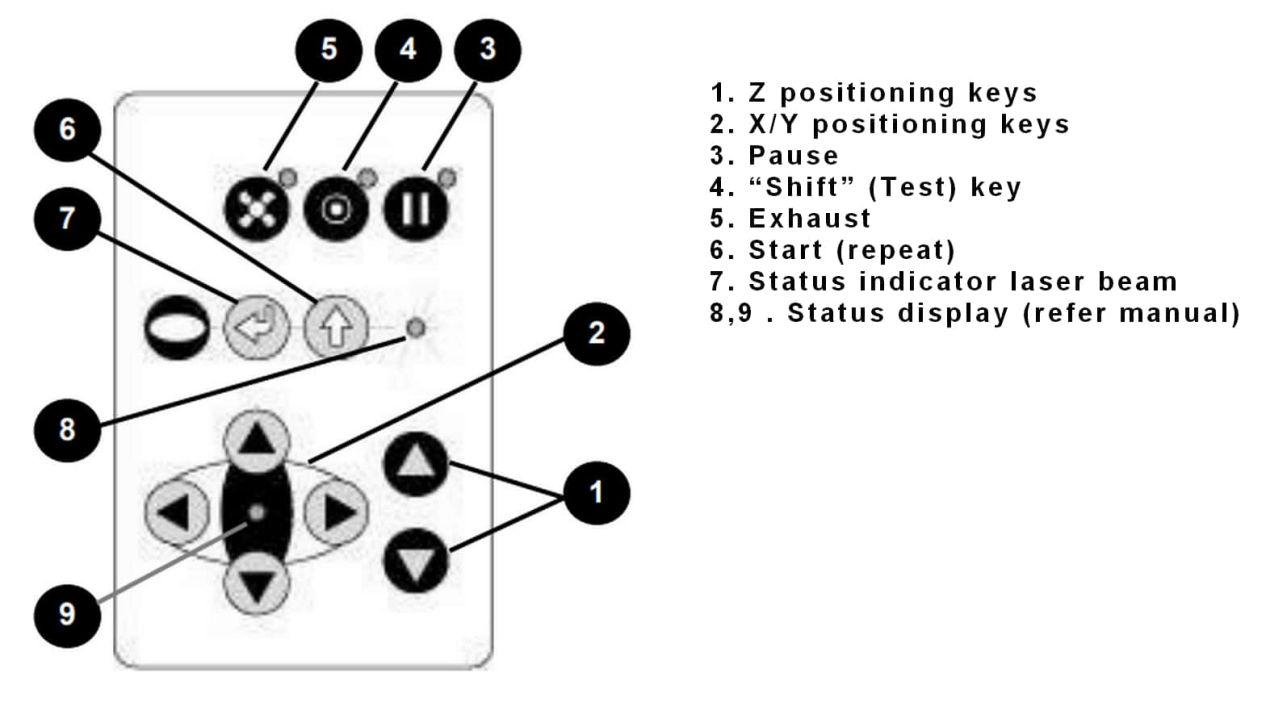
Now, in order to perform a job, we must know few things like setting x and y positions and focusing the laser by adjusting the z position. There is a keypad on the lower right corner at the top face of the machine which is used to navigate the machine.
Here is a link to some tips and tricks which you can use during laser cutting and engraving.
Group assignment
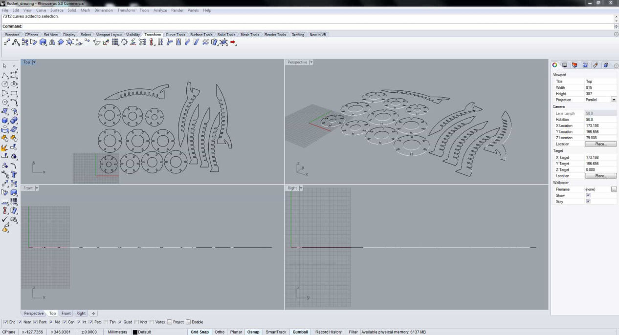
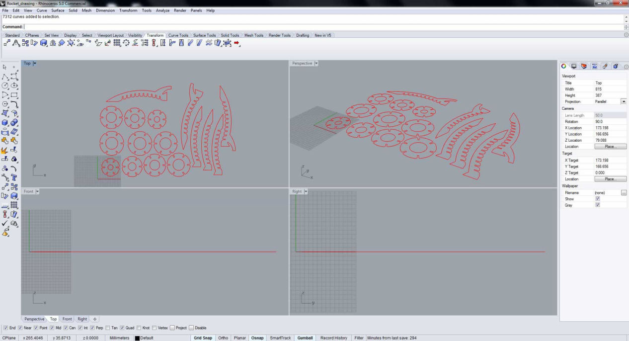
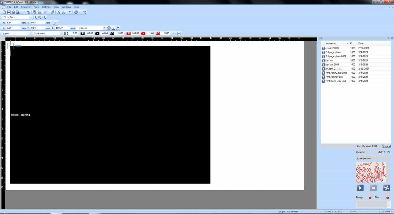
Now in order start cutting, you need to send the file to laser via Job control.We can send the file from different softwares like inskscape, rhino etc to the job control but for now we will be using rhino.
As Laser is a 2 axis device it needs 2D file. It does not matter if it is a vector or a scalar. Since we are designing to test the kerf, we need the shape accurate so I am using CAD to make a dxg file. After you have exported dxf file, import it in rhino.
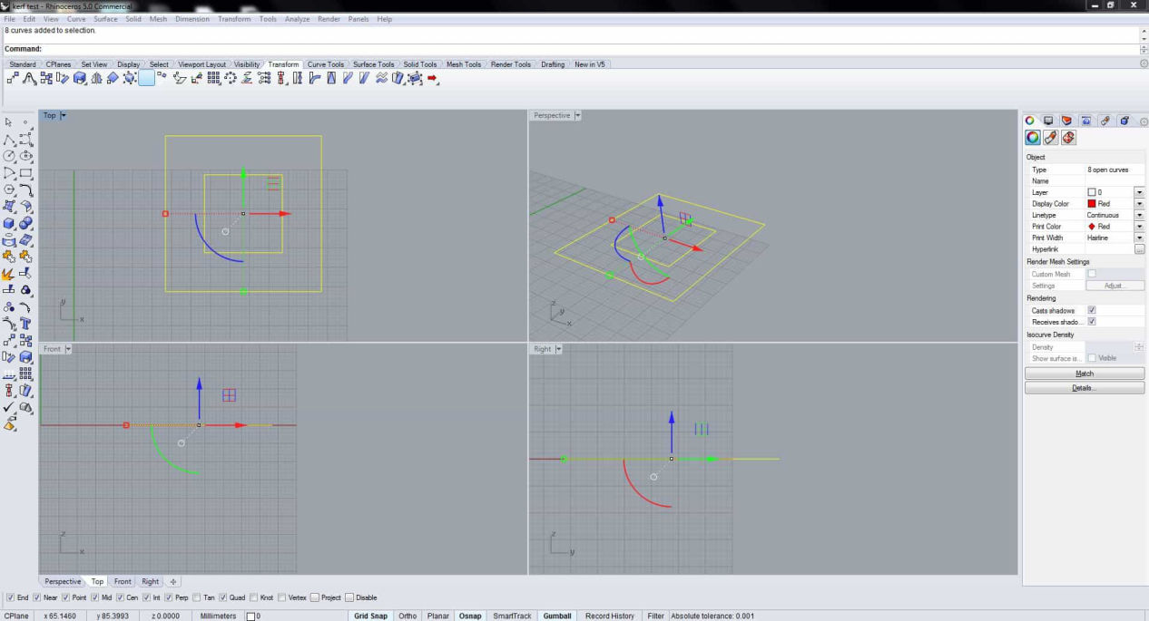
The line is kept red because later in the job control, you will see what is red assigned for in the process. You can select other colors if you want to do process like engraving and controlling the depth according to power, velocity and frequency of the laser cut.
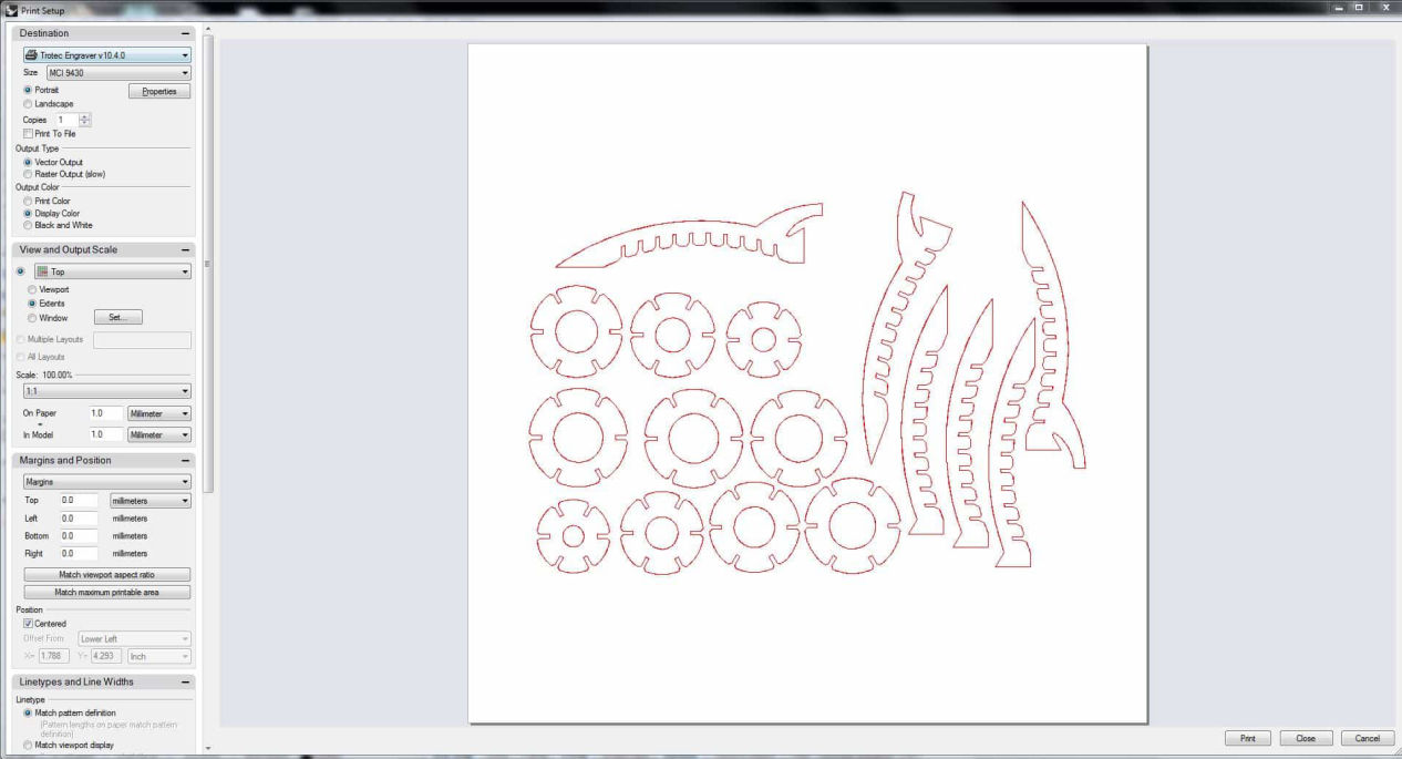
Then click print from the toolbar menu or simply press Ctrl+P and select Trotec as the printer. Make sure the ratio is 1:1 and all the shape falls in the print area. You can slect different materials in this platform or also can use Job control to set the material and parameters. After you click print, it should take you to the Job Control which sends the data to the printer.
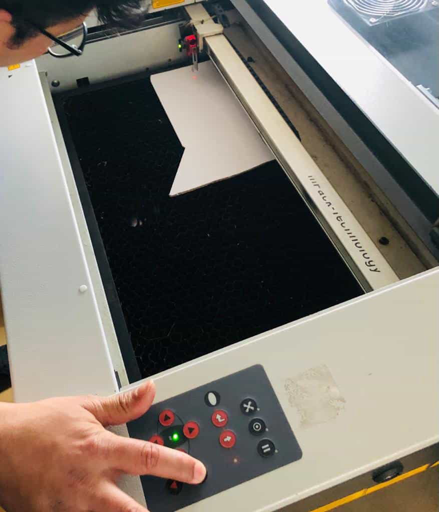
Turn on your laser cutter and after it auto levels make sure the XY is positioned and laser is focused as explained earlier. You can turn on the Exhaust filter just before the job starts.
After the job control is opened press ready on the lower right corner of the job control. It should give you the cross point where the laser head is located. Simply drag the file to the reference start point.
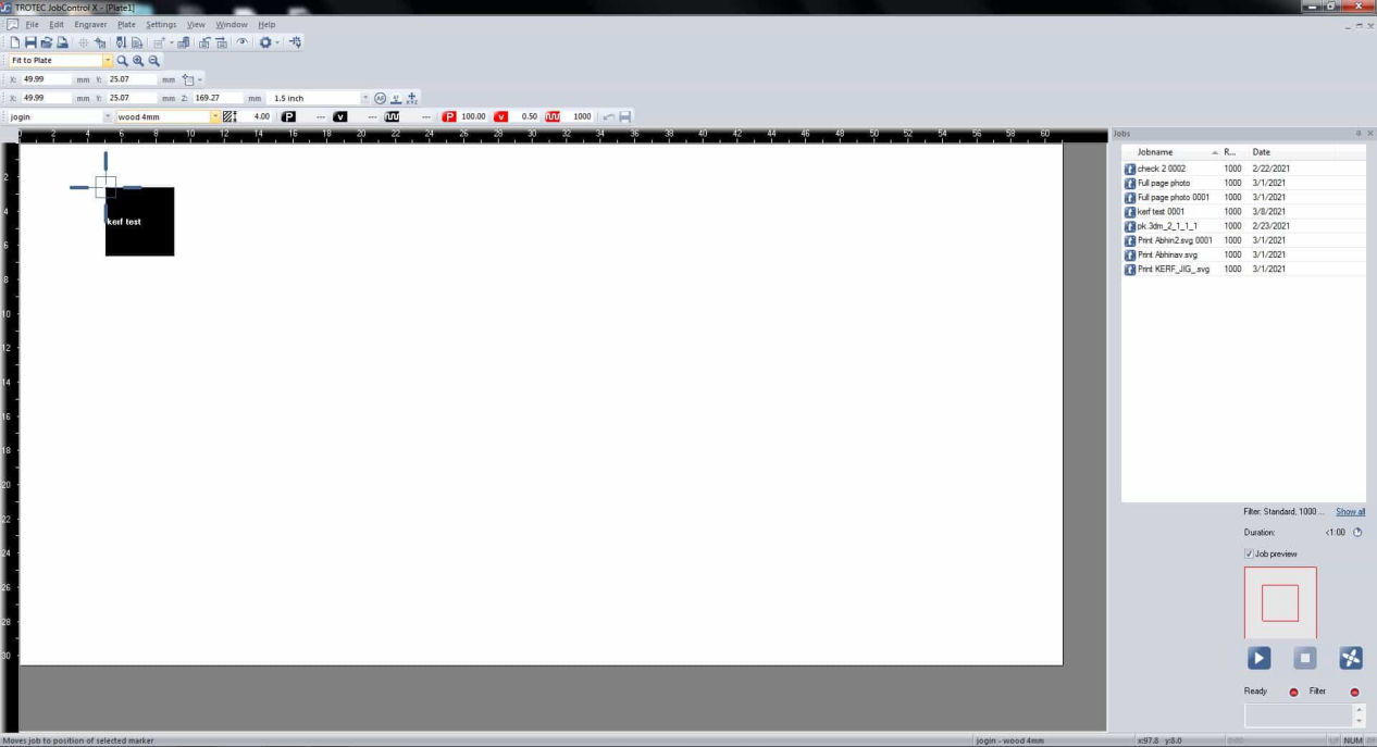
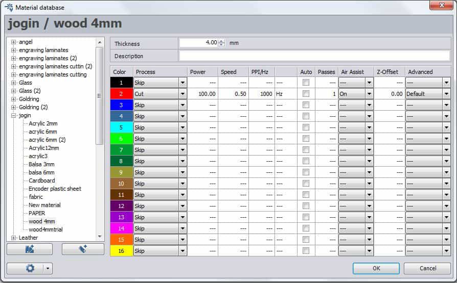
Now set the material as per your requirement in the following material darabase and inspect your cut.
Now after the part is cut, two things had to be found out, one is kerf and another is to find out fitting size.
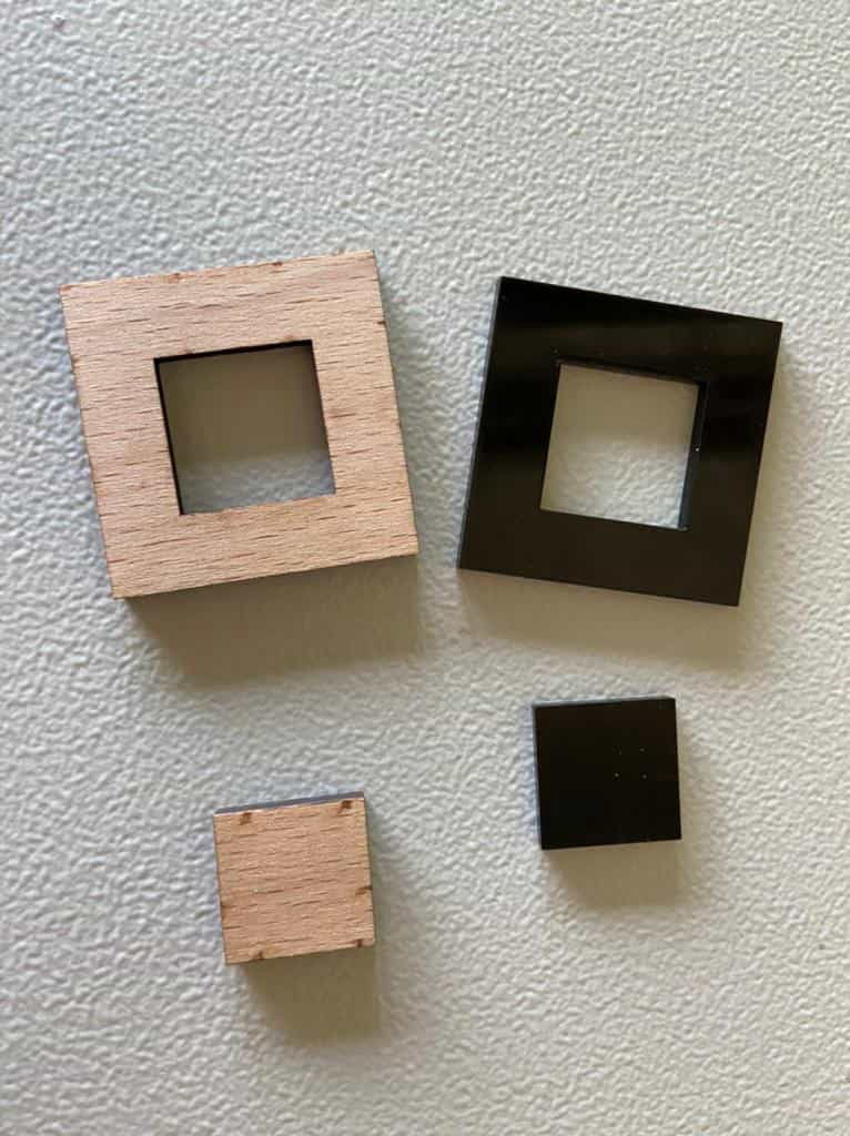
Kerf
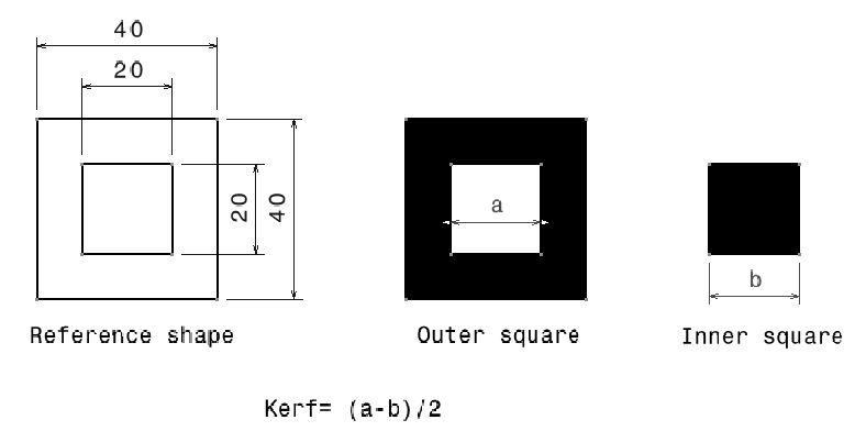
Kerf by definition is the width of material that is removed by a cutting process. For Laser, it is the material removed by laser while cutting. Normally it is the diameter of the tool i.e laser beam in laser cutter. For every material, it is different. For this, as mentioned before we calculated it by subtracting inner dimension from the outer followed by dividing it by 2.
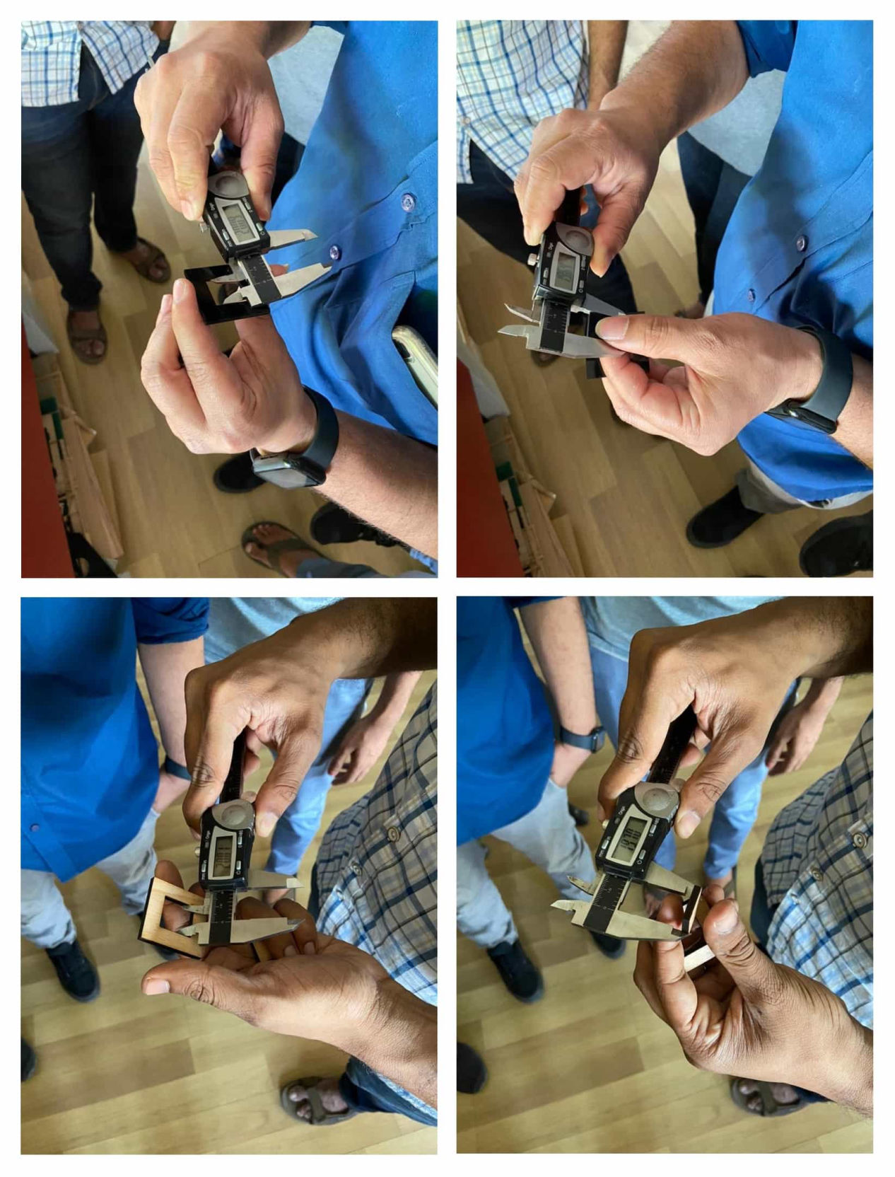
By following the process, the Kerf for 4mm balsa wood was found to be 0.15 whereas for acrylic it was 0.2
Joint Clearance/overlap
Joint clearance is the clearance between the mating parts two connecting bodies. There are three types of fits which care clearance, transition and interference fit. You can choose according to your requirement. Please refer this reference to know about different types of fit.
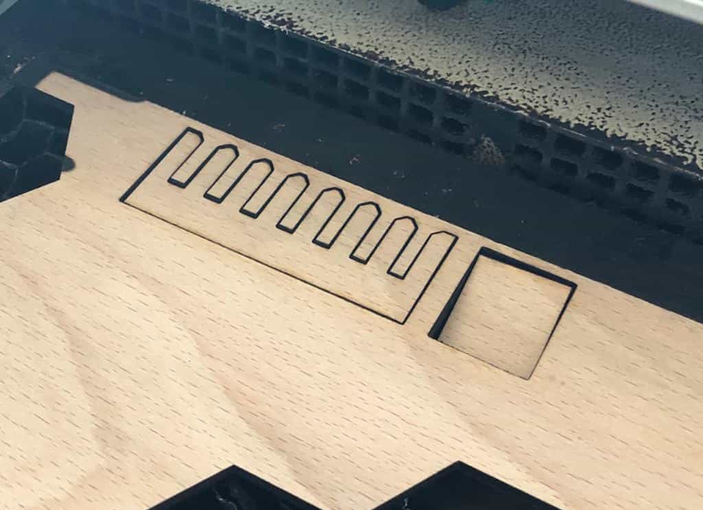
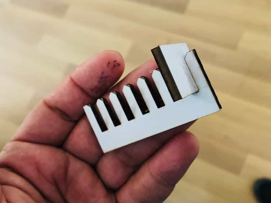
Then keeping the standard thickness of 4 mm, jig with slots starting from 3.4mm to 4 mm with 0.1 increment is parametrically designed and made with the same laser cutting setting used while making kerf jig.
Specifically for the solar panels installed in streets, no one is cleaning them and though they are installed, they are not working properly due to the dust.
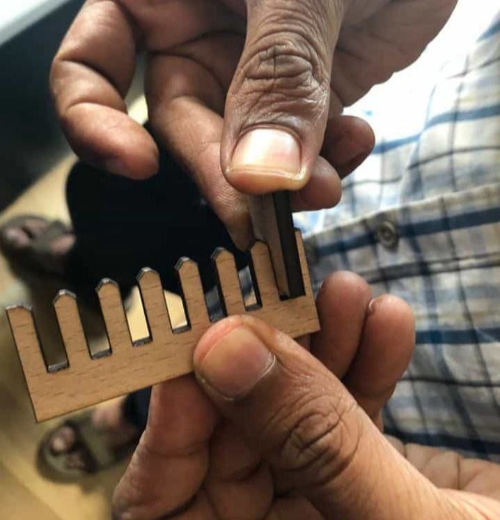
The the fit was ok with 3.5mm slot but was rigid with 3.4mm slot which means if we want to keep a rigid fit, we need to keep overlap of 0.45 mm total and 0.225mm for one side. So the dimension of the hole should be (thickness-kerf-overlap=4-0.15-0.45 = 3.4mm). This will be used to design the parts.
As per individual assignment, we have to use cardboard with thickness 3.45 mm thickness was used.For this first we need to find kerf as well as overlap needed for the rigit fit. Hence same process was repeated.
The kerf was fouind to be 0.23 mm and the overlap to be 0.87 mm, i.e the slot should be (3.45-0.23-0.87)mm = 2.35 mm
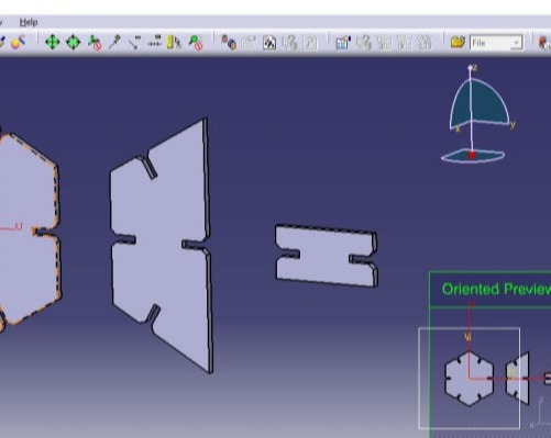
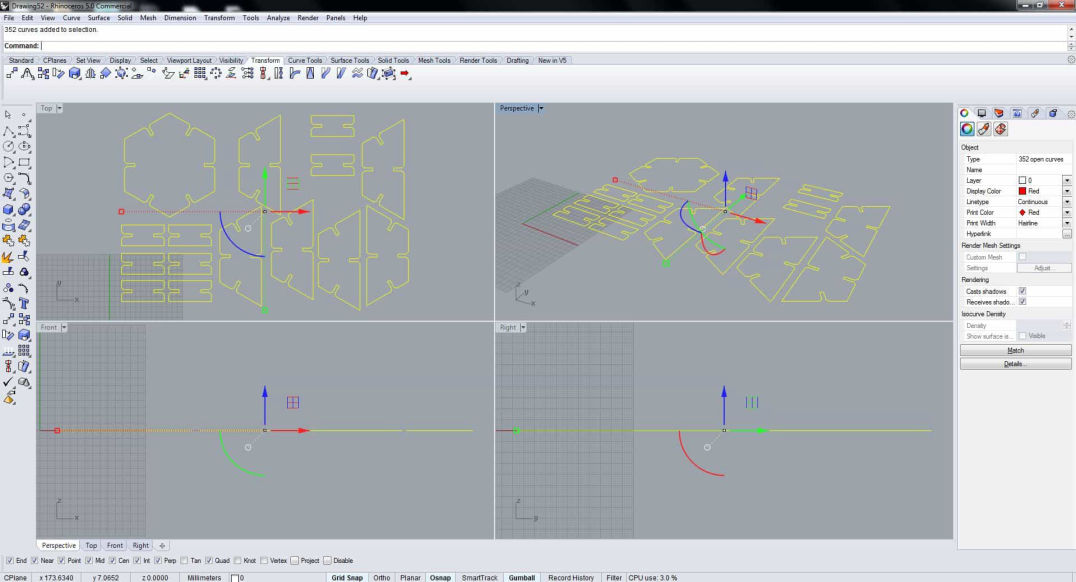
The parametric model was then converted according to the kerf and overlap and as shown earlier was first converted to 2D layout with proper nesting and transferred to dxf Then the file is imported to rhino.
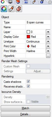
Next selecting all the line properties are changed according to the requirement, i.e. cutting, with following parameter.
Keeping the selection in the top view press print. Make sure that the ratio is 1:1 and the shape fits in the displayed box and click on print which should take you to the Job Control.
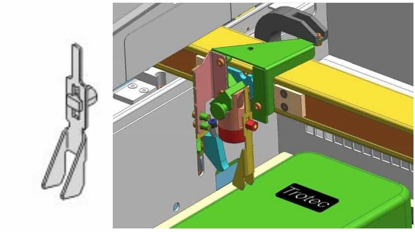
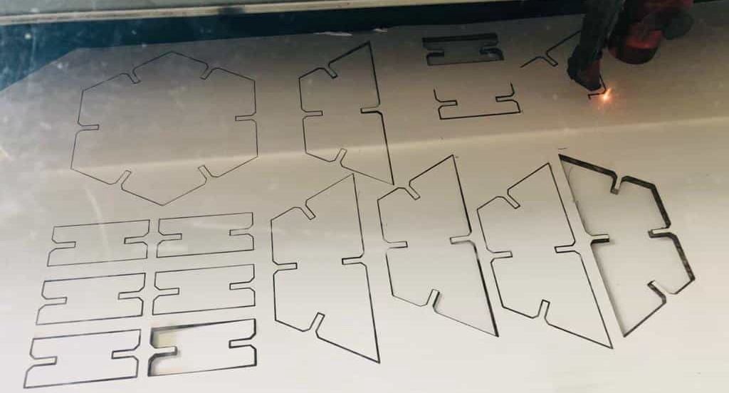
Then the Laser cutter was turned on, the material was placed which is sufficient to cut the design. Then laser head was kept above the material and focusing was done.
X/Y position is set and then the file that is shown in the Jobname is dragged on to the working space such that the top left edge if the job lies on the reference cross of the laser pointer.
Then the material was set as cardboard with the following setting.
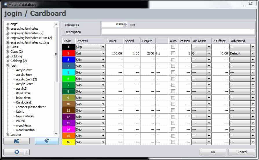
Then make sure that the lid of the laser is closed and the exhaust system is turned on and press ready which should start the job in laser cutter. Make sure that you are fully present when the process is going on and make sure there is no fire in the chamber. And in no time, your job will be ready to be taken out. Leave it for some time for gases to go out through the exhaust system and take out the parts.
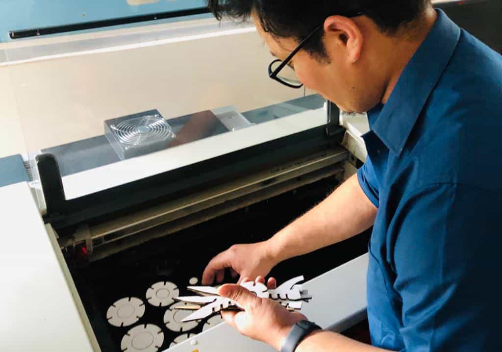
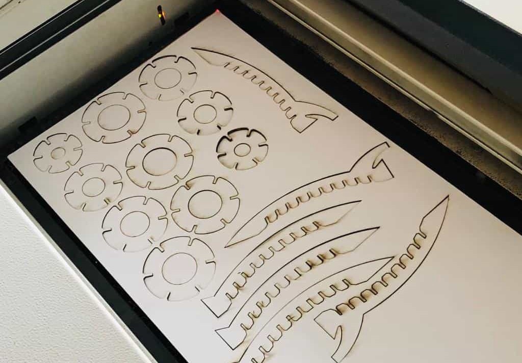
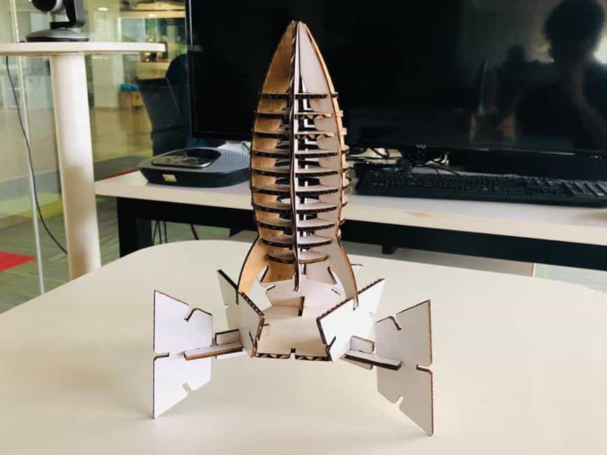
Now assemble it and the product should be ready.
Modular design for the platform
Now for the modular design same process had been followed and is shown in the following images.
This website was started with Mobirise themes