Group
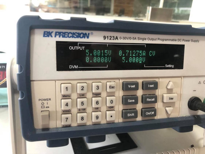
1. Measure the power consumption of an output device
Individual
1. Add an output device to a microcontroller board you've designed,
and program it to do something
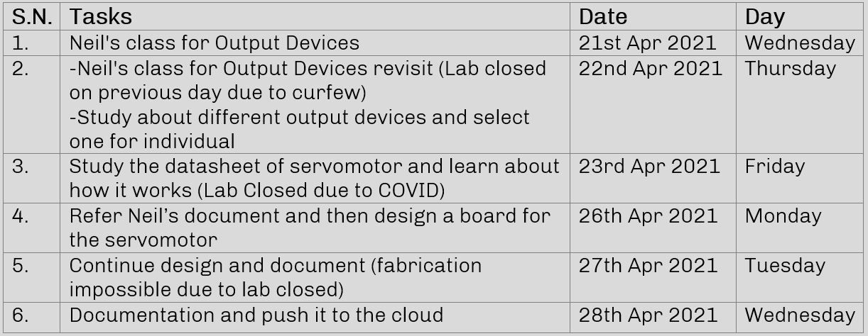
Plan for the week
An output device is any hardware device receives a data or a signal from another device to actuate itself in any sort of way that human can sense either by seeing, feeling, hearing, or smelling. may be tasting. A basic example of an output device that we use in our daily life is TV, fan, computer screen, screen of mobile phone, motors, etc. Output device can exist with or without sensor like input devices. I can operate according to sensor or from the signal recieved from microcontroller.
Talking about our daily life, there are many other output devices that are in the machines that we use for our living which our life becomes very hard. Anything except biological things that we can sense mush have an output device through they actuate to perform something or show something. Output devices take some input as an electrical signal from the main board to perform different tasks life moving, displaying, pumping, making sound, etc.
Ouput devices in Electronic circuits
Output devices in electronic systems transform electrical energy into another type of energy, such as light, sound or kinetic energy.
There are different types of output devices according to our requirement and funtionality of the product. Some basic output devices are as listed below.
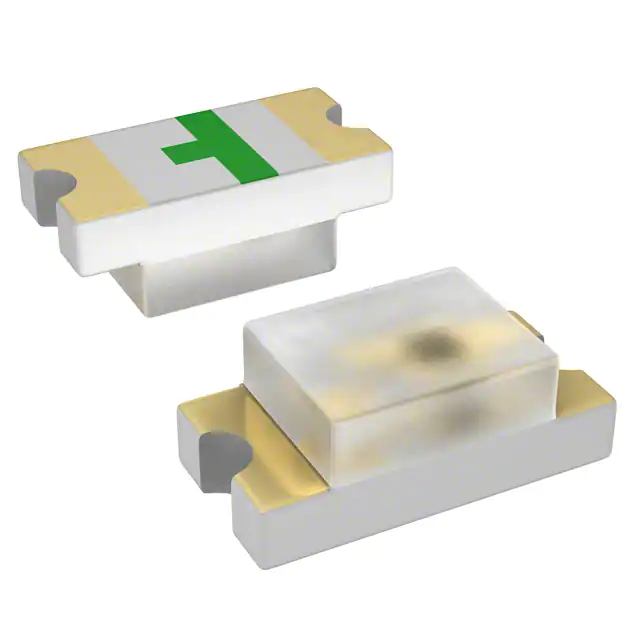
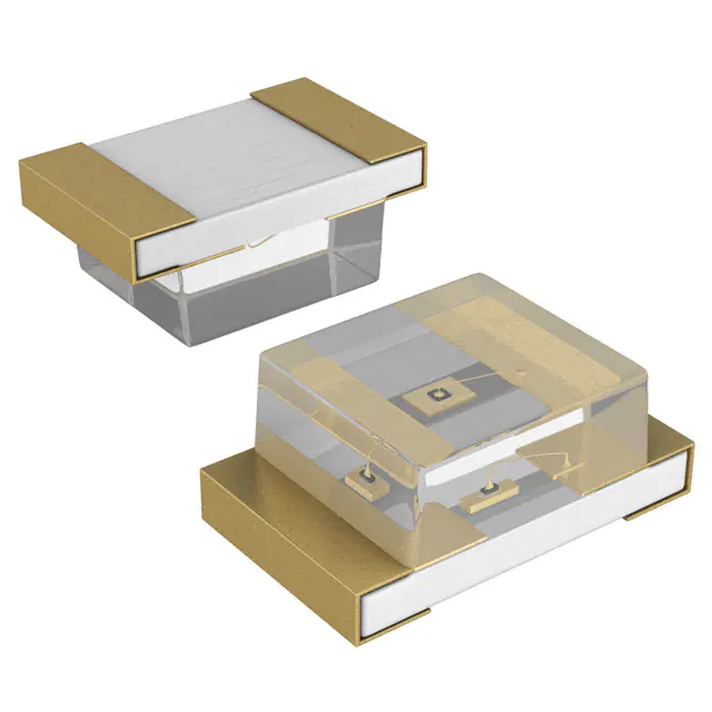
LED is a semiconductor device that emits infrared or visible light when charged with an electric current. It is one of the most used output device in a circuit. It is one way and should confirm the datasheet for the connection path. They are used to indicate something out of the circuit. There are different kind of LEDs in the market which have different current specification due to type of light it emits and should be taken care of when selecting the resistor which is connected with it in series.
The RGB LED generally has a common anode with each of the cathodes for the red, green, and blue LEDs individually pinned out for a total of four different pins. The common anode is connected to the positive power supply, while each of the individual red, green, and blue LEDs are switched on by connecting them to the microcontroller through which we can control the intensity thus controlling the color of the light emitting through the diode.
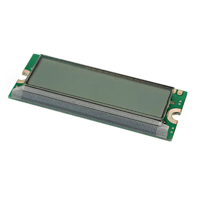
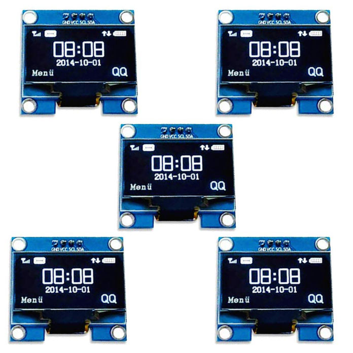
LCD (Liquid Crystal Display) is a type of flat panel display which uses liquid crystals in its primary form of operation.
LCDs are used in a wide range of applications, including LCD televisions, monitors, instrument panels, indoor and outdoor signage, etc.
An organic light-emitting diode (OLED or organic LED), is a display technology in which the emissive electroluminescent layer is a film of organic compound that emits light in response to an electric current. The image coming out of it is best in the price ratio.
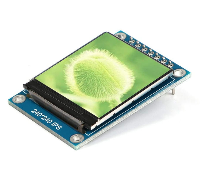
It is a type of LCD with a thin film transistor(TFT) attached to each pixel. They have improved image qualities such as addressability and contrast. Used in television sets, computer monitors, mobile phones, handheld devices, navigation systems, etc.
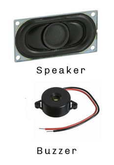
Speakers are transducers that convert electromagnetic waves into sound waves. The speakers receive audio input from a device such as a computer or an audio receiver. This input may be either in analog or digital form. Analog speakers simply amplify the analog electromagnetic waves into sound waves. Since sound waves are produced in analog form, digital speakers must first convert the digital input to an analog signal, then generate the sound waves.
Buzzers are also known as sounders, piezo buzzers, audible alarms, audio indicators and piezo transducers. They are piezo or electro-mechanical devices that produce a sound when an AC or DC voltage is applied. This sound is usually a single buzz tone, although dual tone and fast/slow pulse sounders are available. Buzzers driven by DC voltage, Audio Indicators, contain an internal drive circuit.
(source: www.abcomponents.co.uk)
Normally buzzers are used if there is just and indication sound due to its cost, size and current that it draws.
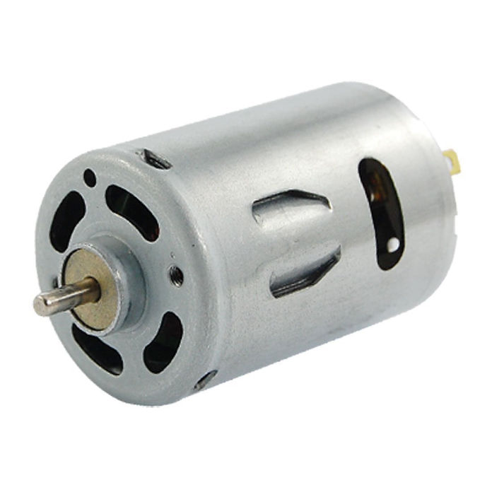
It is an output device that converts electrical energy into mechanical energy. In a DC motor, the input electrical energy is the direct current which is transformed into the mechanical rotation. It is used where continuous rotation is required like fan, wheels, etc.
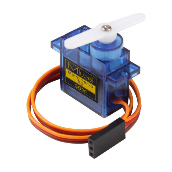
A servo motor is a self-contained electrical device, that rotate parts of a machine with high efficiency and with great precision. The Servo Motor utilizes a regular motor and couples it with a sensor for positional feedback. Its rotation is limited to 180⁰. and are used in robotic arms, legs etc.
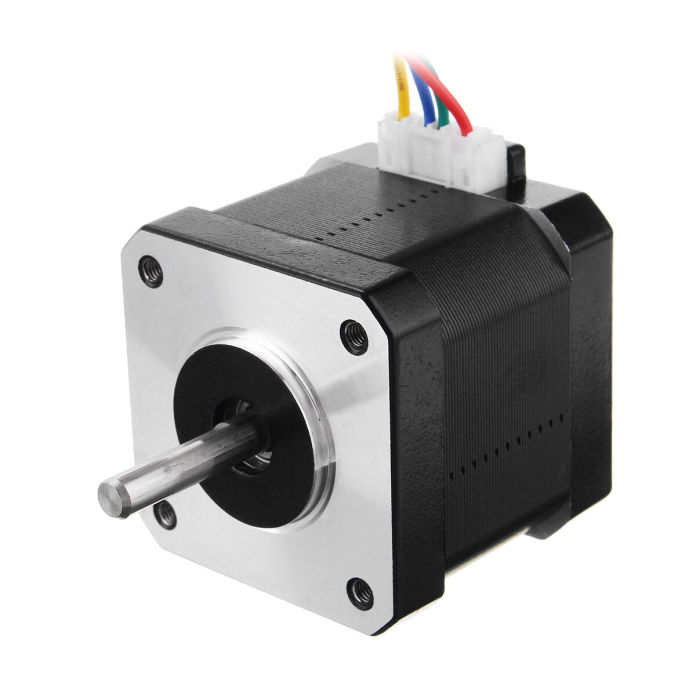
Stepper motor
They are DC motors that move in discrete steps. They have multiple coils that are organized in groups called "phases". By energizing each phase in sequence, the motor will rotate, one step at a time.
With a computer controlled stepping you can achieve very precise positioning and speed due to which they are used for many precision motion control applications.like digital fabrication equiment.
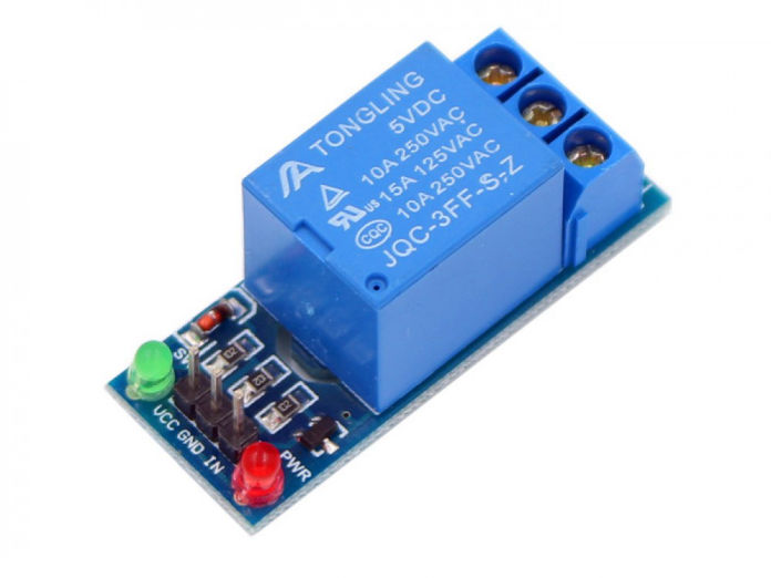
A Relay is an electromechanical device that can be used to make or break an electrical connection. It consists of a flexible moving mechanical part which can be controlled electronically through an electromagnet, basically, a relay is just like a mechanical switch but you can control it with an electronic signal instead of manually turning it on or off. It is used as a switch which operates in low volts as 5V to control device requiring different power supply.
Individual assignment
Servo motor-How does it work?
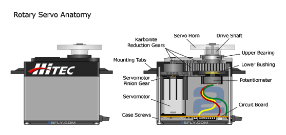
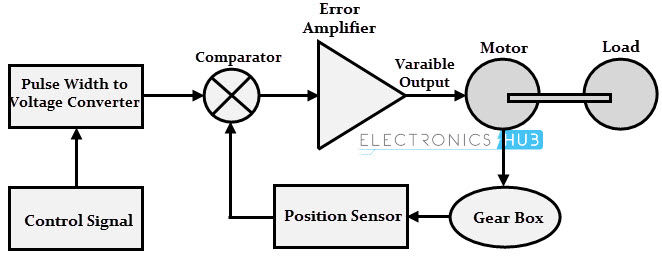
Servomotor as explained earlier is a normal motor which has position sensor and positions accurately according to the pulse provided to the device. Working of Servo motor is based on feedback control. There are three wires on a servo motor, two (High and ground) are for powering the motor, and one is for control signal (Pulse Width Modulation, PWM)
(Source: www.quora.com)
(Source: www.electronicshub.org)
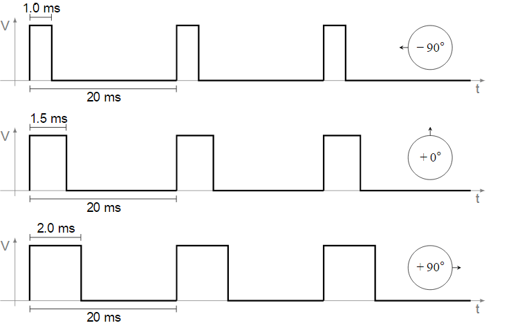
So, reference voltage sets the position or angle of the motor, and motor rotates till the desired position or angle is achieved. As reference voltage is mean of Pulse width signal, by varying On time (duty cycle), we can set the desired angle of the output shaft. A pulse is sent every 20 milliseconds. Width of the pulses determine the position of the shaft. For example, a pulse of
1ms will move the shaft anticlockwise at -90°, a pulse of 1.5ms will move the shaft at the neutral position that 0° and a pulse of 2ms will move the shaft clockwise at +90°.
Servo motors are popularly used in robotics, computers, CD/DVD players, toys etc. Servos are extensively used in those application where a specific task is to be done repeatedly in a very precise manner.
PCB Design
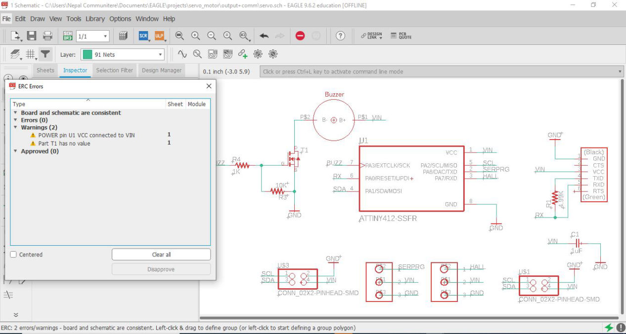
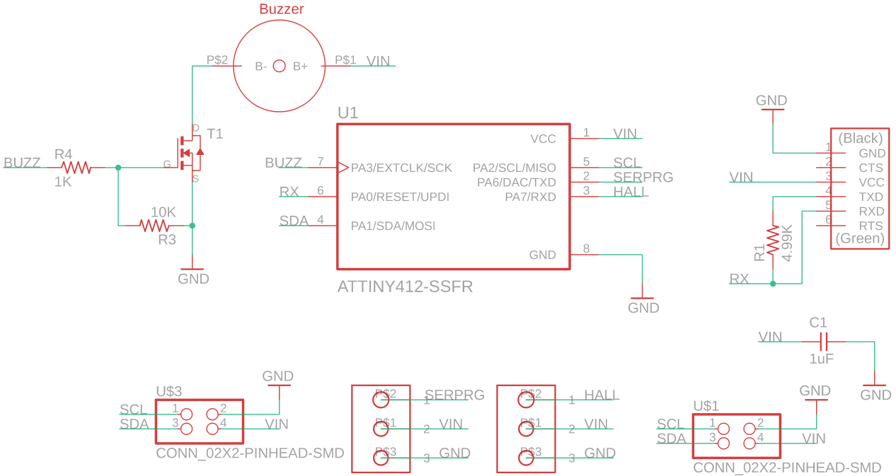
For PCB design as previous week, I used Eagle. Details about how to design the board in Design week. Here I designed the board such that two servos can be connected so that I can program to control two servos at a time from external source as well. First I referred the datasheet of the servo motor from the hobbyking that we are using which can download from this link.
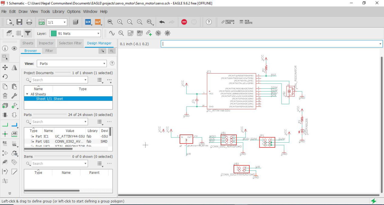
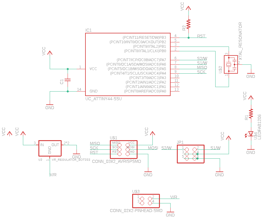
Then I switched to board design followed by setting design rules and then placing the components in proper area to get maximum out of auto route and finally also check via DRC which is explained in this link.
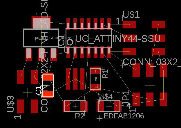
The auto route was done but showed some vias but with the combination of auto and some manual routing, i was able to finally come up with the following board
The traces and trim line can be seen below which i am going to fabricate after lockdown
New design after lockdown.
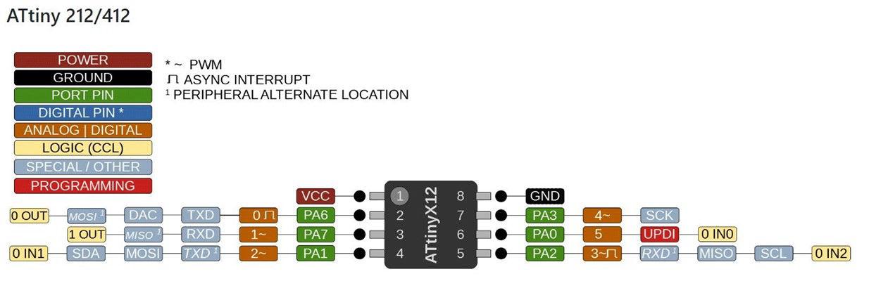
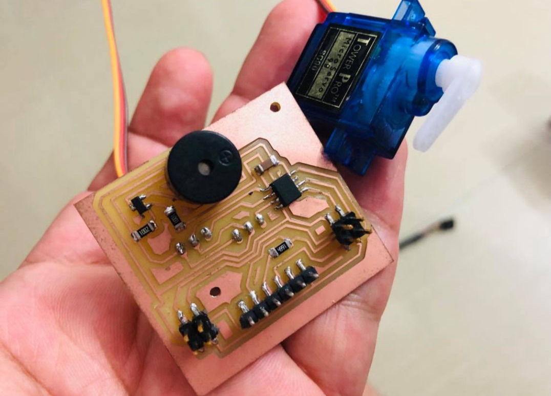
After Lock down was released, this was the first assignment and there were a lot that we have to do along with the project itself so I decided then to include both output week with my final project as my final project also has a servo in the mechanism. Then I started making the board which contains 2 output pins for the output devices and one for the input device as well i.e hall sensor about which you can refer to this link. Here I wanted to use the controller which is just enough for the board asnd also is new for me, ATTiny-412. About this chip you can download the datasheet from this link.
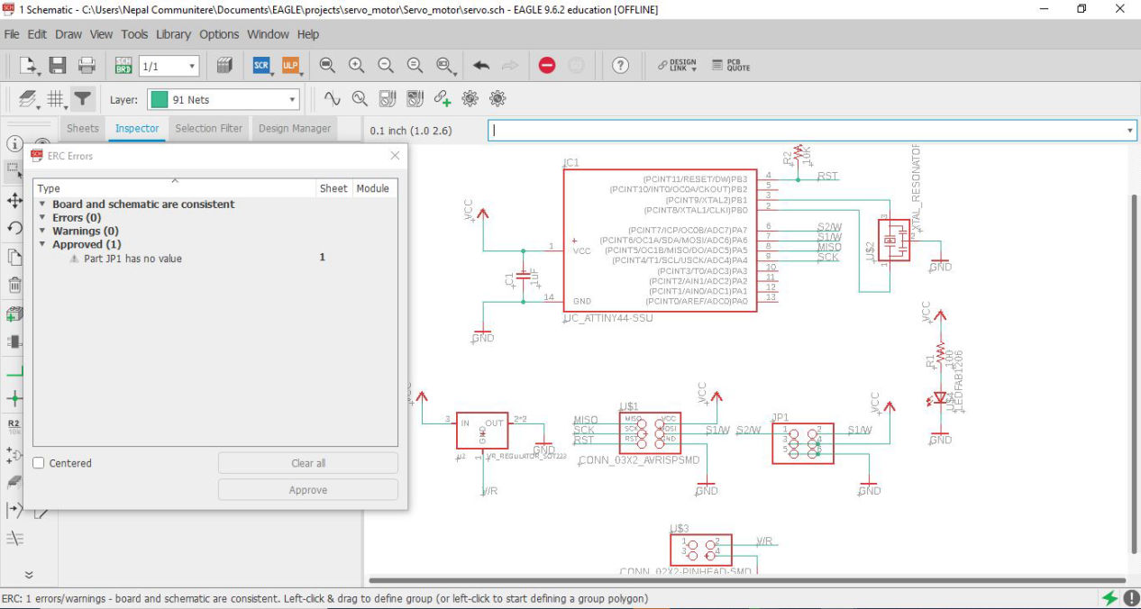
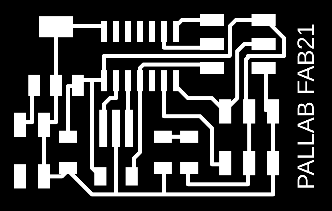
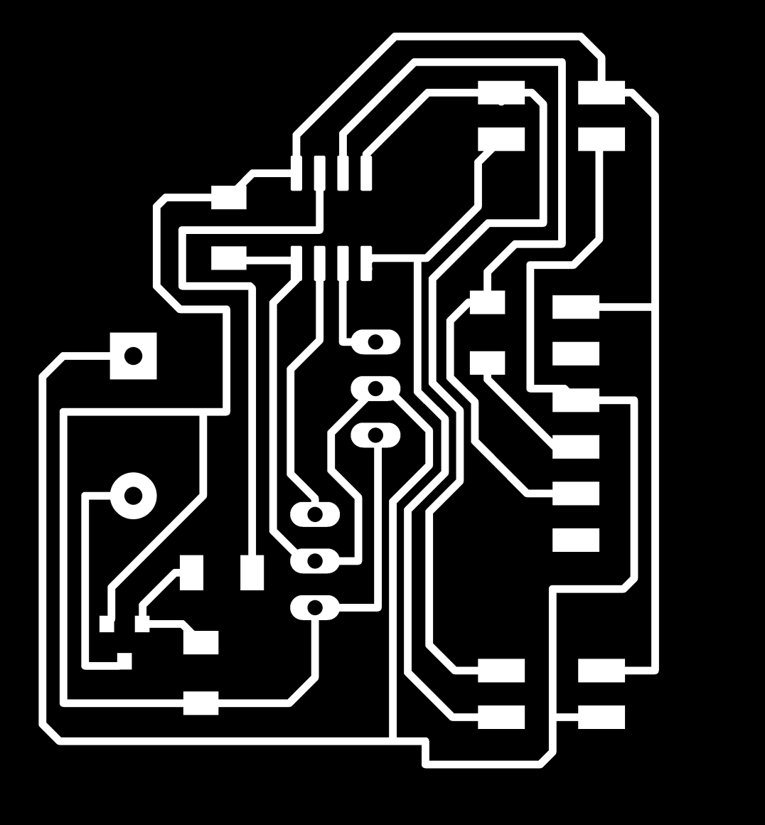
Now moving to the board design, first the design rules were set according to 16 and 32 mill and then combination of autotrace with manual tracing was done.
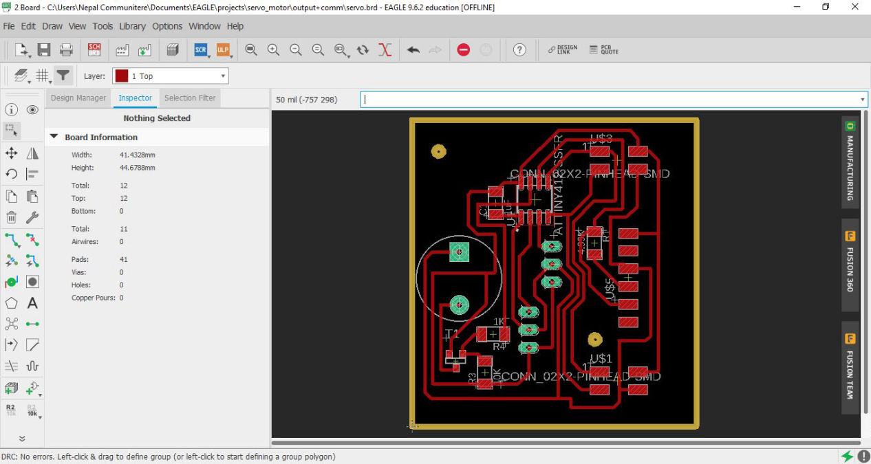
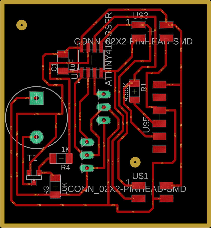
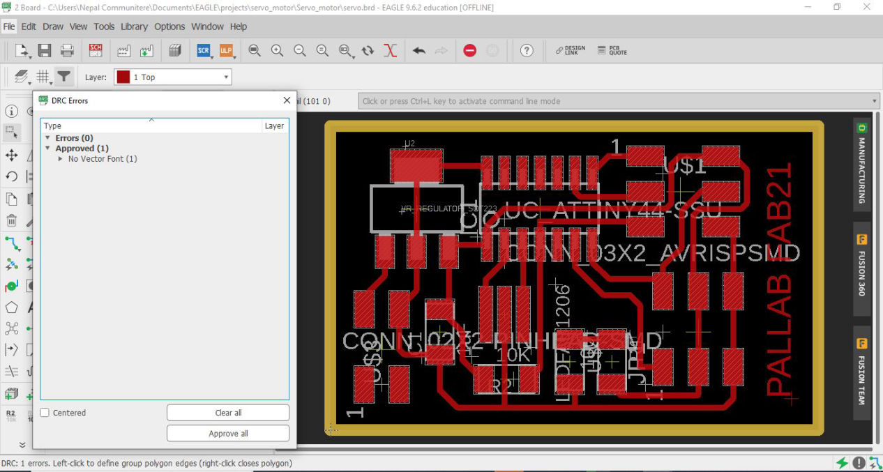
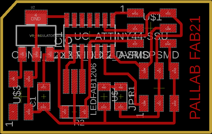
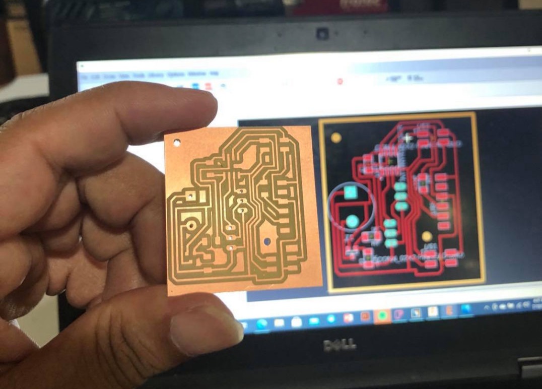
Then luckily there was no error while checking the DRC. You can see that there is no problem with your board is the message you get on the left bottom corner of the window. following are the trace and trim file which were used during fabrication.
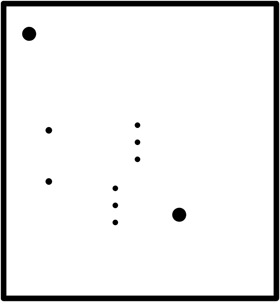
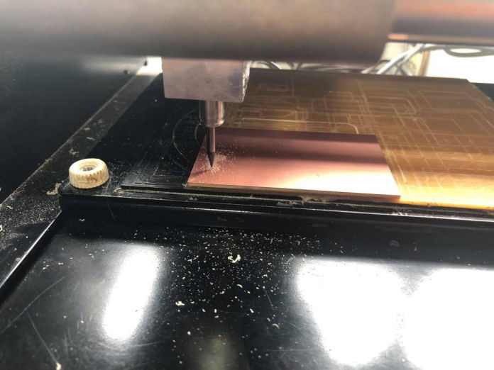
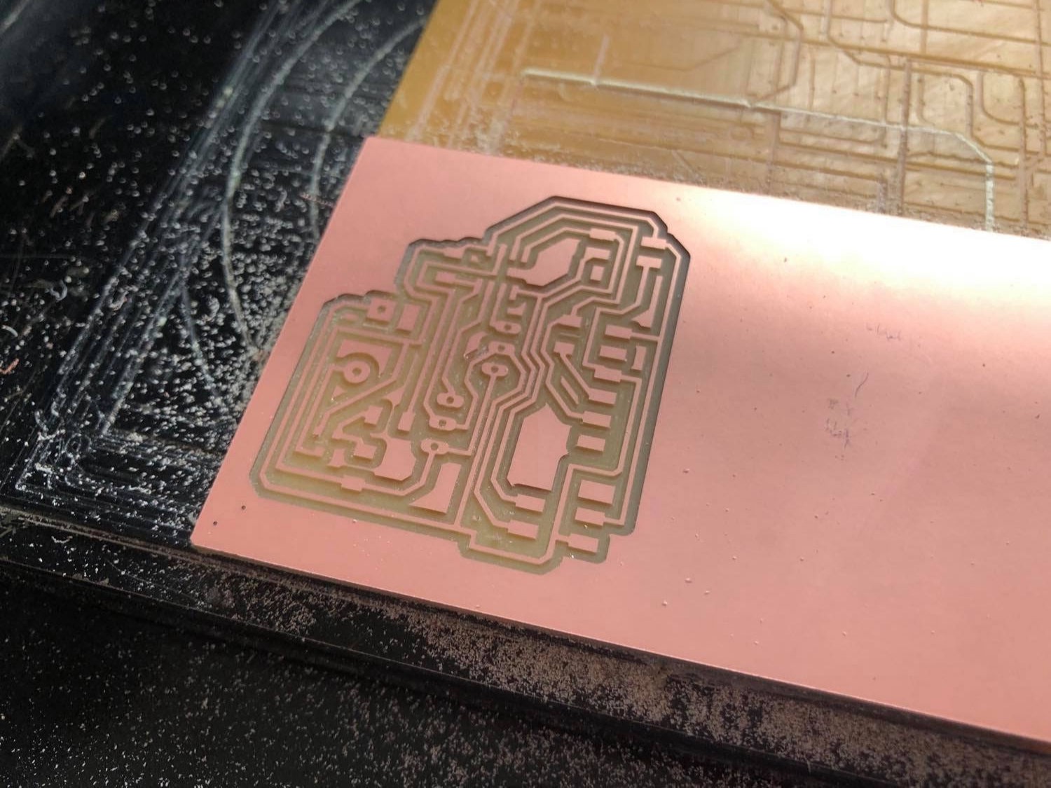
Then, PNG file is exported to PCB milling machine via mods and fabrication process starts. following are some screenshots during fabrication.
Time for Coding
First of all, if you are using arduino IDE, you have to install library for the ATTiny 412. First, in the preferences setting of arduino, add "http://drazzy.com/package_ drazzy.com_index.json". Then Go to Tools >> Manage Libraries and search for megatiny core and install it.
Servo servomotor; // create servomotor object to control a servo
int angle = 0;
int min_angle = 0;
int max_angle = 180;
void setup() {
servomotor.attach(0); // attaches the servo on pin 0 to servomotor
}
void loop() {
for (angle = min_angle; angle <= max_angle; angle += 1) {
servomotor.write(angle);
delay(20);
}
for (angle = max_angle; angle >= min_angle; angle -= 1) {
servomotor.write(angle);
delay(20);
}
}
The main things here are the steps which is the angle increment, and delay time and angle can be added anywhere between 0 to 180 degrees. combination of angle increment and delay time decides the smoothness and the speed of the servo motor. Whereas, the range of movement is defines by min_angle and max_angle.
Here, The pulse of 1 ms (1 millisecond) width can rotate the servo to 0 degrees, 1.5ms can rotate to 90 degrees (neutral position) and 2 ms pulse can rotate it to 180 degree. That means that in each 20ms, only one degree is turned meaning 5.55 microsecond (1ms/180) increment in pulse in each step. This way Servo can be controlled by PWM.
By controlling the above parameters, following result is obtained which I will be using as a function in my final project.
As i already had a buzzer in my board, i was thinking if i can experiment with them. I tried beeping which was not new. It is just passing 1 and 0. So i searched for different songs which could be added to the microcontroller and be played. I came across through cool songs which you can download from the link below. The pin numbers have been changed according to the board above. Below is one video of the buzzer playing stairway to heaven. (Source: link)
Group Assignment
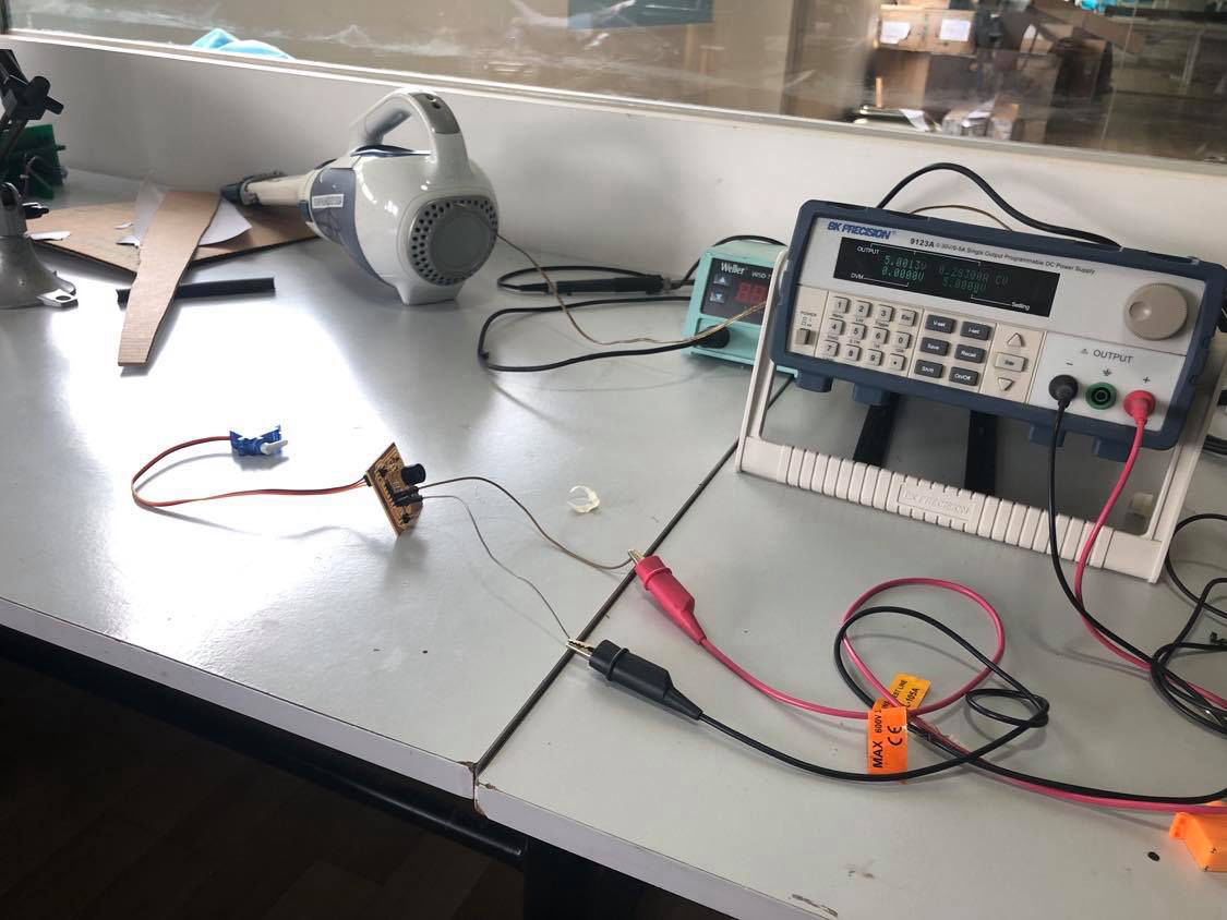
For group assignment, we used our output devices to measure power of it. For my board, I tried to see the power consumption of motor and buzzer as well. For this, I used following coding so that I cas see the difference in current and then find out the power consumption for all.
#define buzz 4
Servo myservo;
int angle = 0;
void setup() {
pinMode(buzz, OUTPUT);
myservo.attach(0);
}
void loop() {
for (angle = 0; angle <= 180; angle += 1) {
myservo.write(angle);
delay(20);
}
delay(100);
for ( angle = 180; angle >= 0; angle -= 1) {
myservo.write(angle);
delay(20);
}
digitalWrite(buzz, 1);
delay(2000);
digitalWrite(buzz, 0);
delay(2000);
}
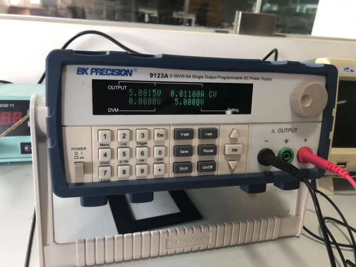
Then the current when all output device was measured as shown in figure below. For servo motor since the current was fluctuating, I provided the load and then the current was constant.

Start a free website with Mobirise