
Computer Aided Design
ModelingOhmmy 🧡
This second week the #academychallenge is to design the final project in 3D and for this we have to explore the world of digital design. The idea is to test 2D and 3D digital design programs, and sketch a a first design.
Previously I've already had some experience with CAD (Computer Aided Design) and I know how to use some programs, but in class we were recommended several open source programs and online platforms that I didn't know yet; this seems very useful to me, since you don't need to buy a license. So I have been encouraged to try some them out.
Michael H. talking about the beginnings
Week 2 Assignment
📆1th February
Refreshingconcepts
As memory is fragile and mine even more so, I will write down here the most used concepts in the world of 2D and 3D digital design.
- Raster: Digital image represented in Pixels. It divides the space into regular cells where each cell represents a single value.
- Bitmap: These are images that are made up of points, called pixels, displayed in a rectangle or table, called a raster.
- Pixel: The smallest unit (of color) that makes up a digital image.
- Vector graphics: escribir escribir escribir
- 2D Design: Digital design made up of two dimensions and has no depth. In this type of design, vector geometric entities such as points, lines, arcs, polygons and fills are integrated.
- 3D Design: Digital design conformed by 3 dimensions (Cartesian axes) where the programs allow to represent in a digital way our ideas through mathematical operations and geometric entities.
- B-Splines: B-splines touch the first and last control points, and can be pulled through intermediate points. Unlike Bézier curves, control points do not allow you to specify the points through which a curve passes when aligning a curve with other drawing elements.
- Nurbs: The Non-Uniform Rational Beta Spline (NURBS) curve is a mathematical formula representing the geometry of curves, angles, circles, arcs, and surfaces in 3D space. Free-form surfaces and curves can be created and edited with high flexibility and accuracy.
- Surfaces: Surfaces are defined by 3 things: A boundary, UV curves, and a surface normal. Boundaries are made from wireframe geometry (lines, arcs, or splines), and define the total area of the surface. UV curves are the curves inside of the mesh that define its surface shape. These are generally distributed along the surface in the “along” direction and the “across” direction.
- Meshes: Meshes are also 3D models entirely made up of linked, non-overlapping, triangles from point clouds taken from a 3D scanning device on a physical part. Since the model is created by scanning, this makes mesh a non-CAD form of computer modeling. Due to the nature of meshes, they don’t contain what we would consider in Mastercam a true “edge”. Mesh models can be either manifold or non-manifold just like a solid. A mesh can be used as machining geometry, but they are generally best suited for organic shapes rather than geometric shapes. This is especially true when a geometric shape contains circular data, as meshes are not capable of creating clean circles.
- Cloud of points: A point cloud is a set of vertices in a three-dimensional coordinate system. These vertices are usually identified as X, Y, and Z coordinates and are representations of the external surface of an object.
- Render: The Render is a digital image that is created from a 3D model or scenario made in a specialized computer program, whose objective is to give a REALISTIC appearance from any perspective of the model. This 3D model is subjected to various processes, which with the use of texturing techniques of materials, lighting, distribution, as well as photographic techniques, create a series of optical effects that resemble a specific situation in the real world, resulting in a Photorealistic image, i.e., that appears to be a photograph (the most common goal of 3D artists).
- Animation: While animation consists of giving life to those objects that do not have it, in 3D animation, in addition to this, these objects can be rotated and moved in a three-dimensional space, unlike 2D animation, in 3D animation, the frames must undergo a rendering process once the model is finalized.
- Simulation: 3D Simulation is the act of imitating the functioning or behavior of a system or group of systems of the physical world by means of a digital model in 3 dimensions, it is the exposition or production of hypotheses in research that aim to imitate a form, behavior or reaction.
Final projectsketching
To come up with the design for my final project, I sat down to explore the idea in more depth. Ohmmy will help you to have the ideal oxygenation ratio. But how am I going to achieve this?
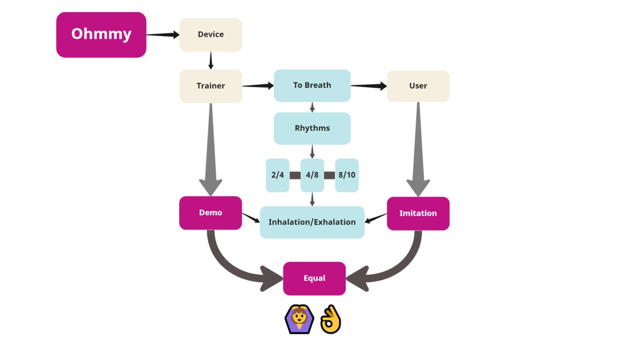
This device is an interactive training assistant to learn how to breathe correctly and with controlled rhythms (like Yoga breaths). The difference between this product and an App, is that this device allows you to physically interact with it and therefore the user will have a more sensory experience.
How does it work?
The breathing trainer with rhythm, through interaction with light, shows us the correct times how to do yoga breaths, it has 3 options for breathing rhythms. The user must imitate what he sees on the backlit surfaces 1 (inhale) and 2 (exhale). The lights are staggered and will mimic the breathing cycle; inhale and exhale.
The device will sense some of these options: Perhaps sense the moving arms, the pressure applied with the touch of the hands or the user's breath. And this imitation (of the user) will activate the illumination of two more surfaces that, if the user is performing the breathing correctly, surfaces 3 (inhale) and 4 (exhale) should show the same rhythm as surfaces 1 and 2. The device will have the added bonus of aromatherapy to make the whole routine very friendly and a concentration of various senses; which allows you to use it while you are not exercising during the day.
Diagram
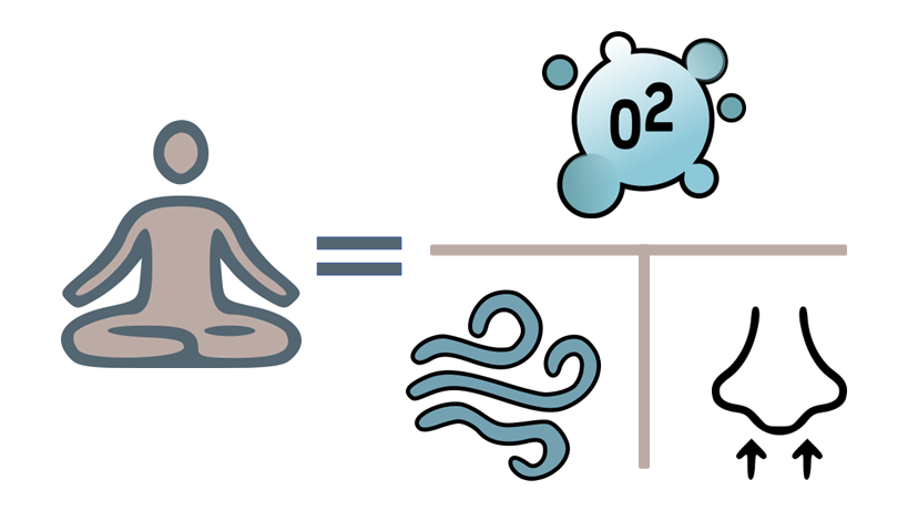
Diagram proportion
Operation
RasterSketchbook
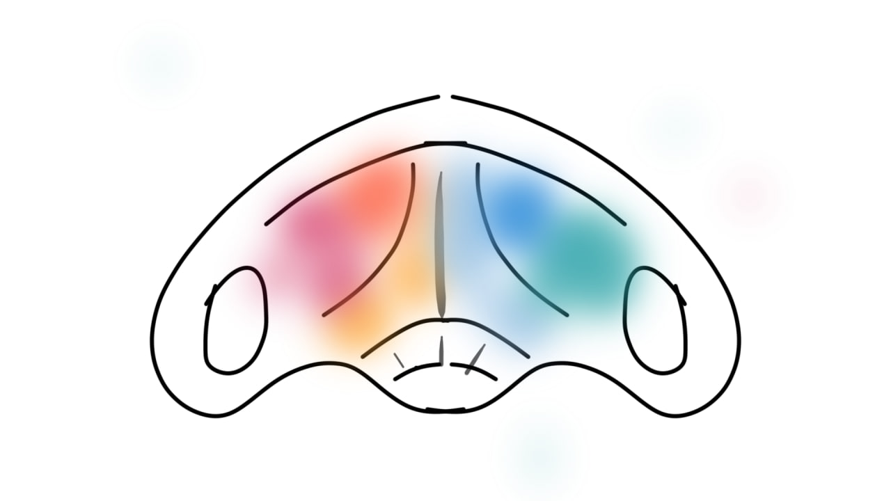
To have an approach to my idea graphically I looked for an application that allows me to express it. Before I had used the Sketchbook app which is from autodesk and is free. So I gave it a try. The idea was to represent how the lights were going to represent the moments of inhalation and exhalation of oxygen that occurs when we breathe.
This drawing is in plan view, looking from above. And it brings to mind butterflies, the lightness and colorfulness of their wings.
Sketchbookis a Raster application, that is to say, it allows us to draw and paint and to obtain images in .jpg, .png, etc. But it has the particularity that you can get gifs and also videos from frames, this functionality has been very useful to express my idea in 2D.
Operation
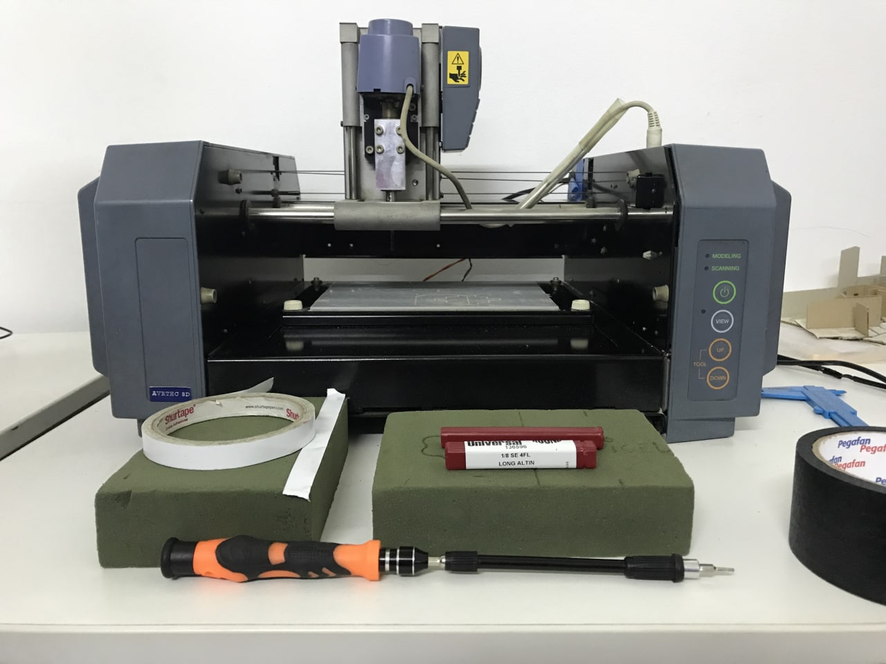
Modela MDX-20 & floral foam
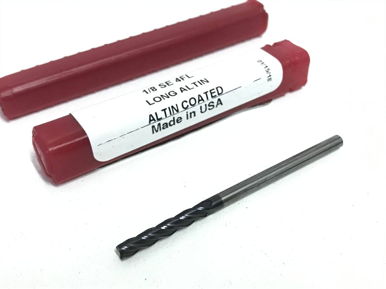
Carbi-Universal 1/8" SE 4FL cutter
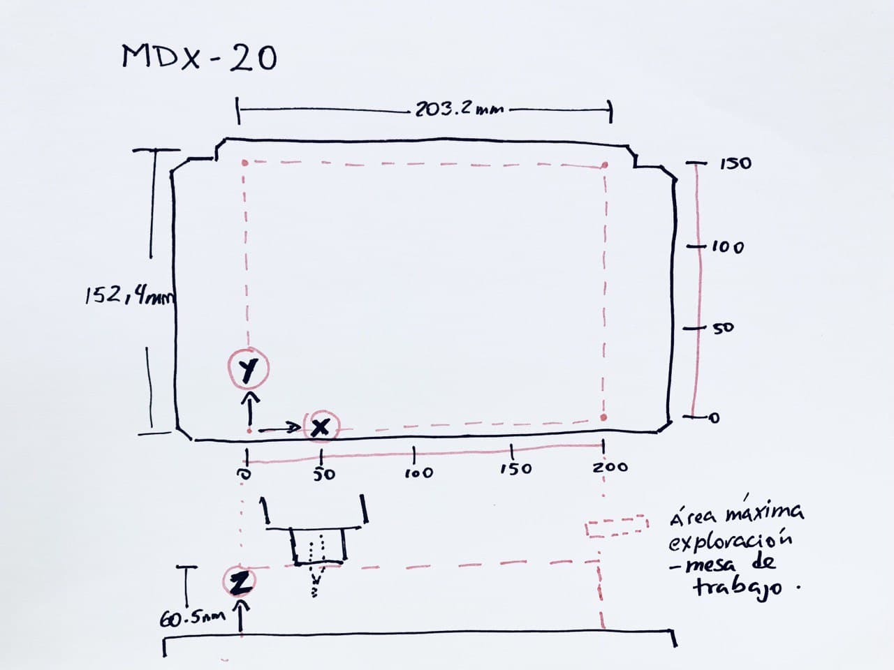
Maximum working area Modela MDX-20
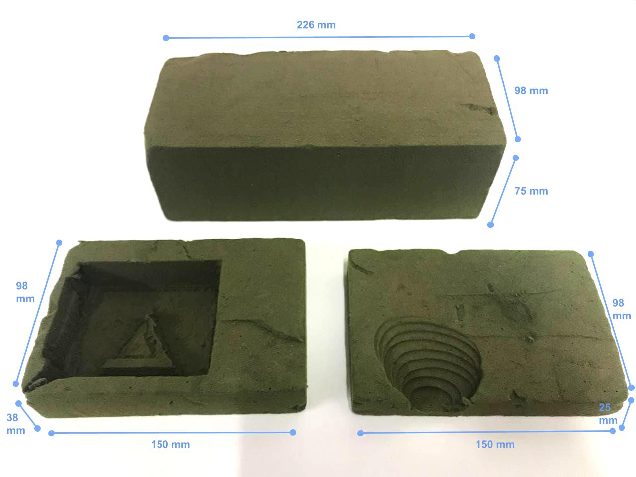
Foams cut to size
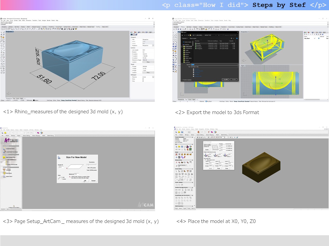
To do the cutting test, we downloaded a file of an egg mold (👉here) to test on the foam. We have already used the ArtCam program in week 7, when we cut with the CNC "something big". We explored this a little more and saw that there were functionalities to do 3d machining.
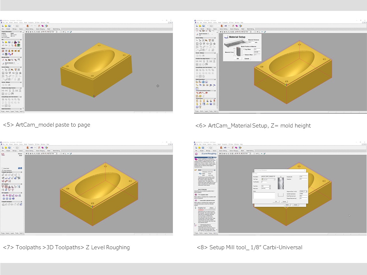
The process I did is as follows: first, check that the geometry of the 3d model is correct and fully closed. Then I imported the file to ArtCam in 3ds format and there I filled in all the machining parameters. For example, if we want the cut to be raster or offset, the Z measurement of the foam block and other factors. Also, I uploaded all the features of the mill tool. We tell the program that the CNC spindle make ramping movements when it descends from one level to another on the Z axis. This helps us to take care of our part, the machine and the milling cutter. The "ramping" movement is very convenient so that the cutter doesn´t hit at a perpendicular angle directly with the hard material and starts cutting laterally. In week 7 you can see about it.
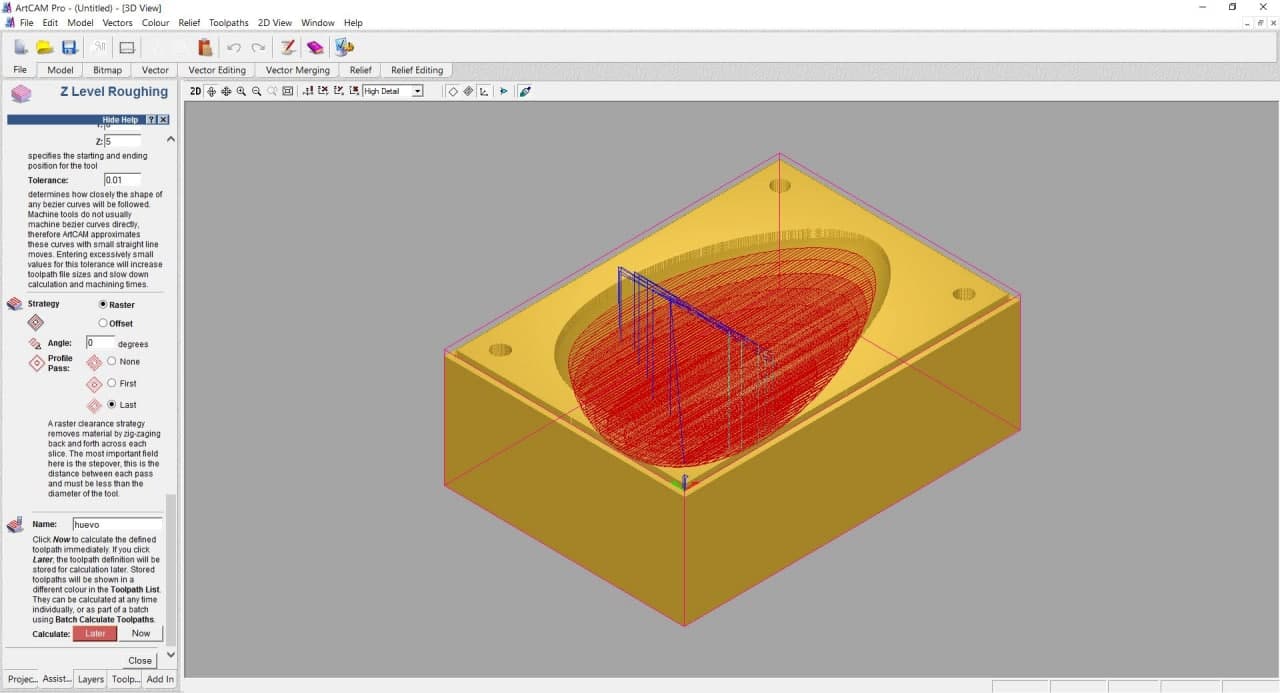
Raster milling Egg Model in ArtCam
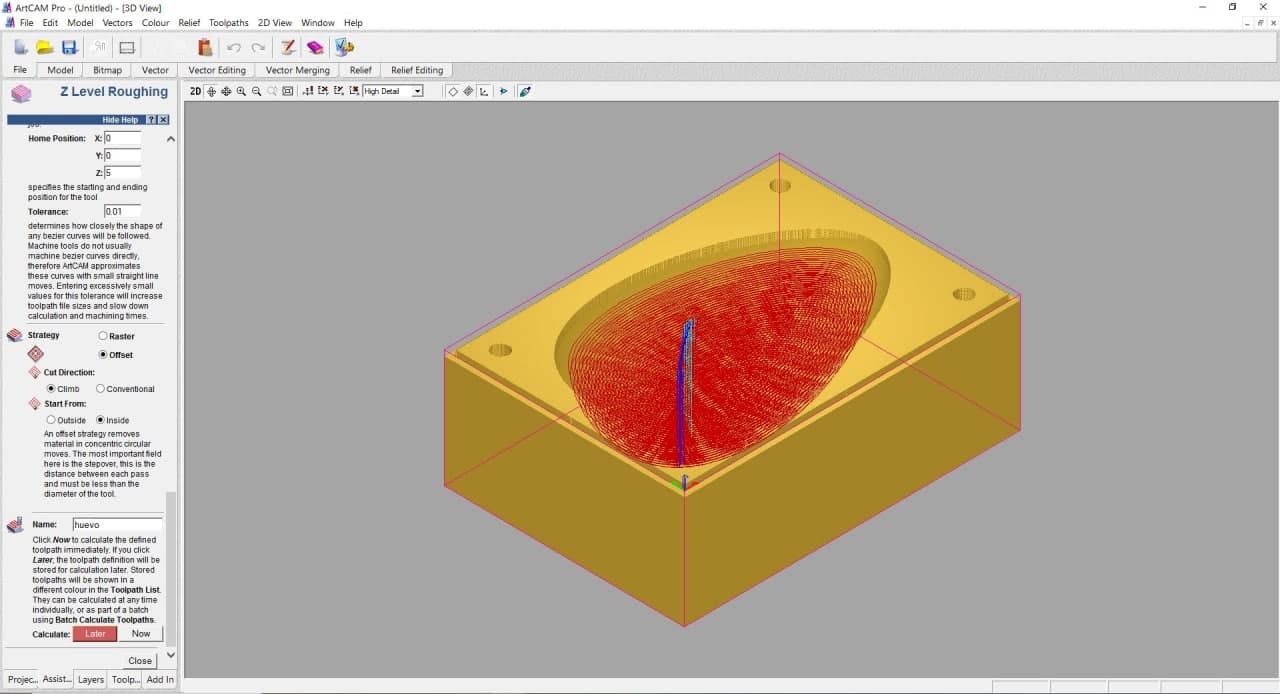
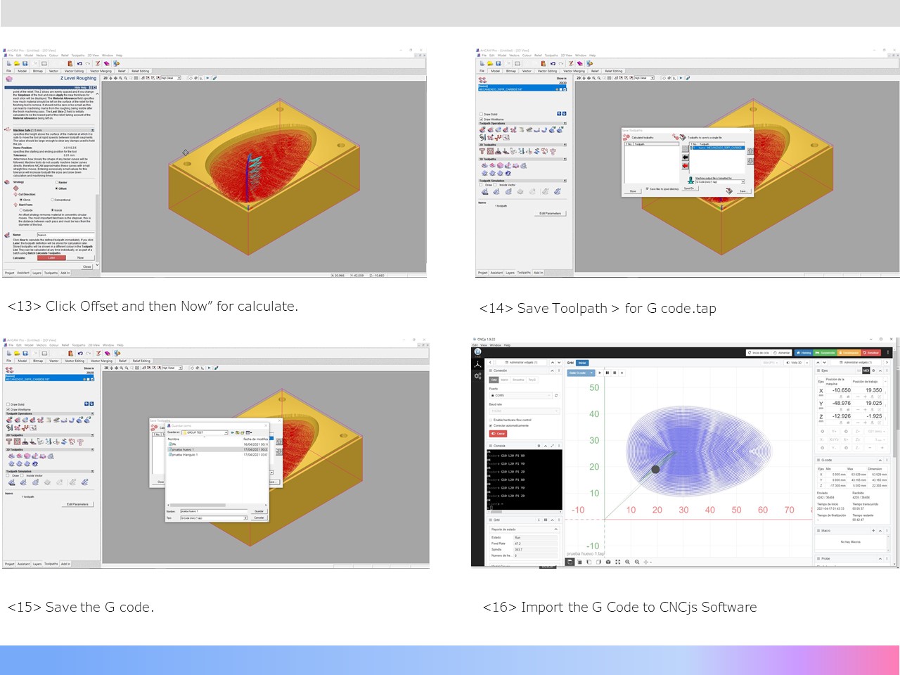
Offset milling Egg Model in ArtCam
Z Level Roughing_ArtCam
Z Level Roughing_ArtCam
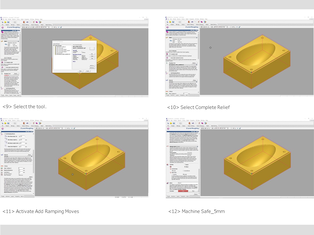
Z Level Roughing_ArtCam
Z Level Roughing_ArtCam
We chose the egg mold because it is a curved and organic shaped that would allow us to test the quality and cutting precision of our machine. While I was solving this part, Mayra investigated in tutorials and designed how to solve the design of a mold with a triangular design in the FreeCad program, which would help us to visualize and explore how the machine would behave when machining right angles, direction changes and different depths. To share the information learned and send each one a test model to be machined. Finally, we sent the EGG mold test to be machined with the CNCjs program applying the Offset option and we waited for the result.
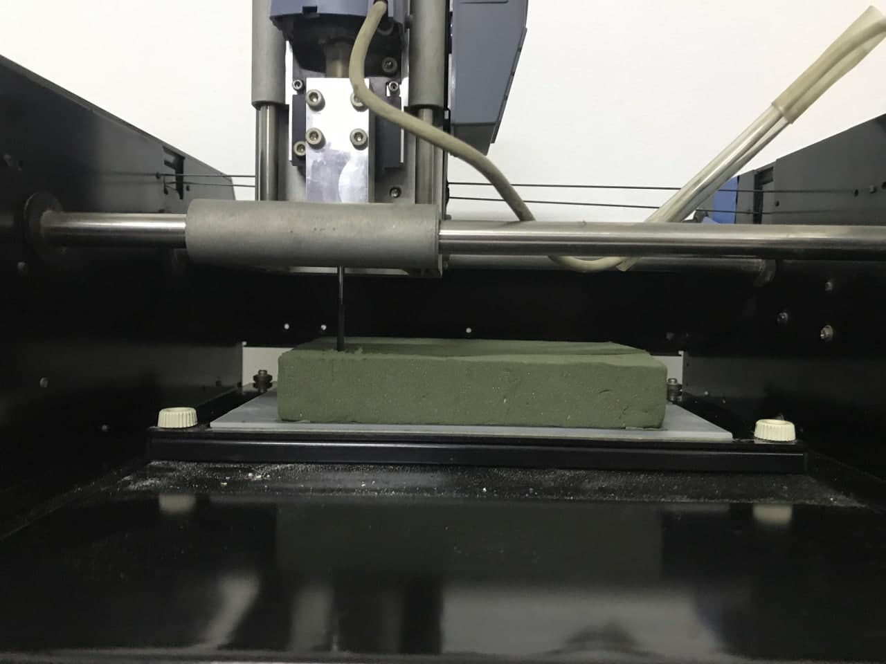
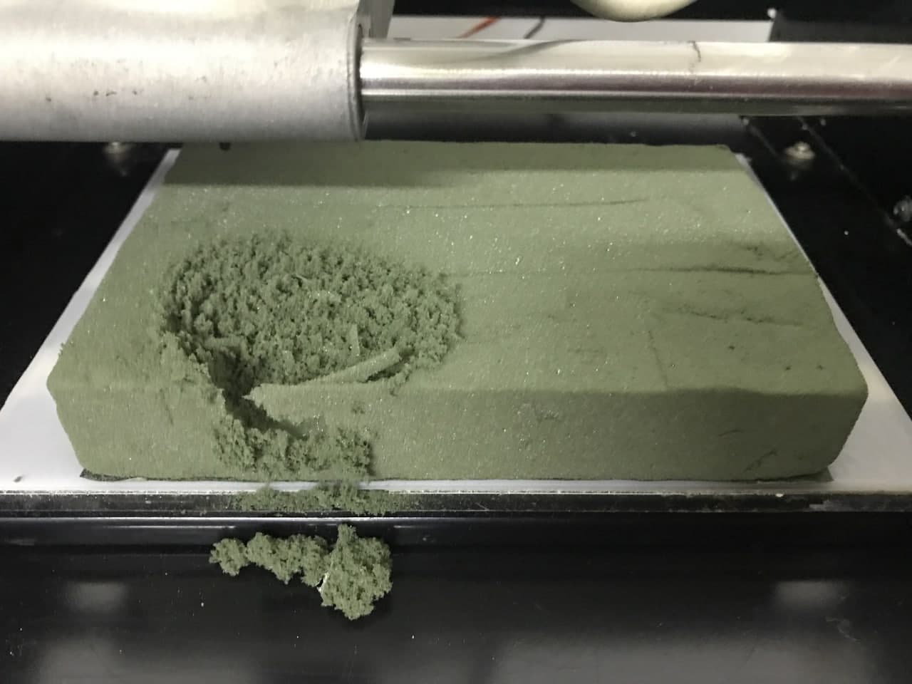
Z height_Egg mold machining process
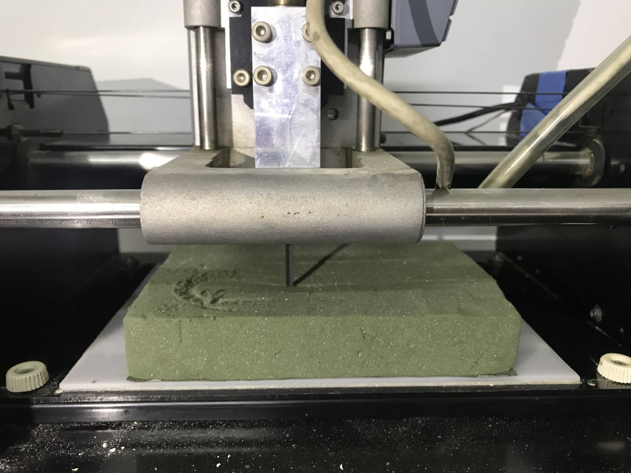
Egg mold machining process
Egg mold machining finish
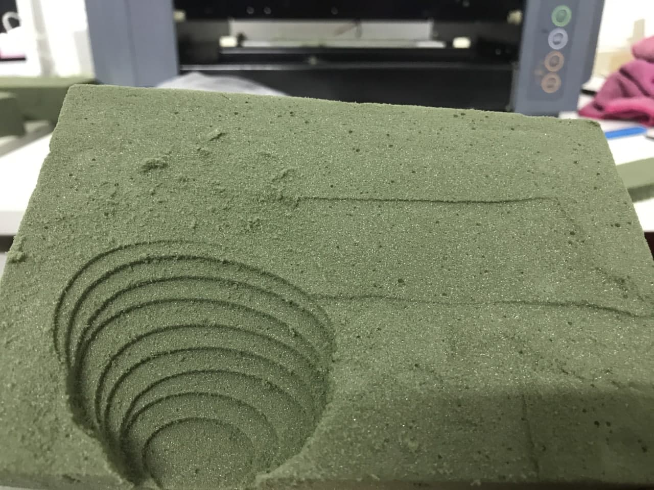
Egg mold machining finish
ConclusionScrambled egg, not cooked!
The G code generated by the ArtCam was correct, however, the final result was not what was expected. The mold was not exactly half an egg. They looked like more Inca platforms. 🌄 We detected that every time the Z-axis dropped in level, the tool was out of phase on the -Y axis and on the +X axis, which is clearly noticeable in the foam mold.
We tried to solve the problem from all the software we use, but we realized that the main problem laid in the Modela MDX-20 machine, which was not calibrated, much less accurate, after having been revived after ten years of being turned off. Also now it works with free software and Arduino, but not the original.
In any case, we reviewed, cleaned, and refined it, with the support of Eduardo Chamorro (Fab Lab BCN), to make a second attempt with the Triangular design.
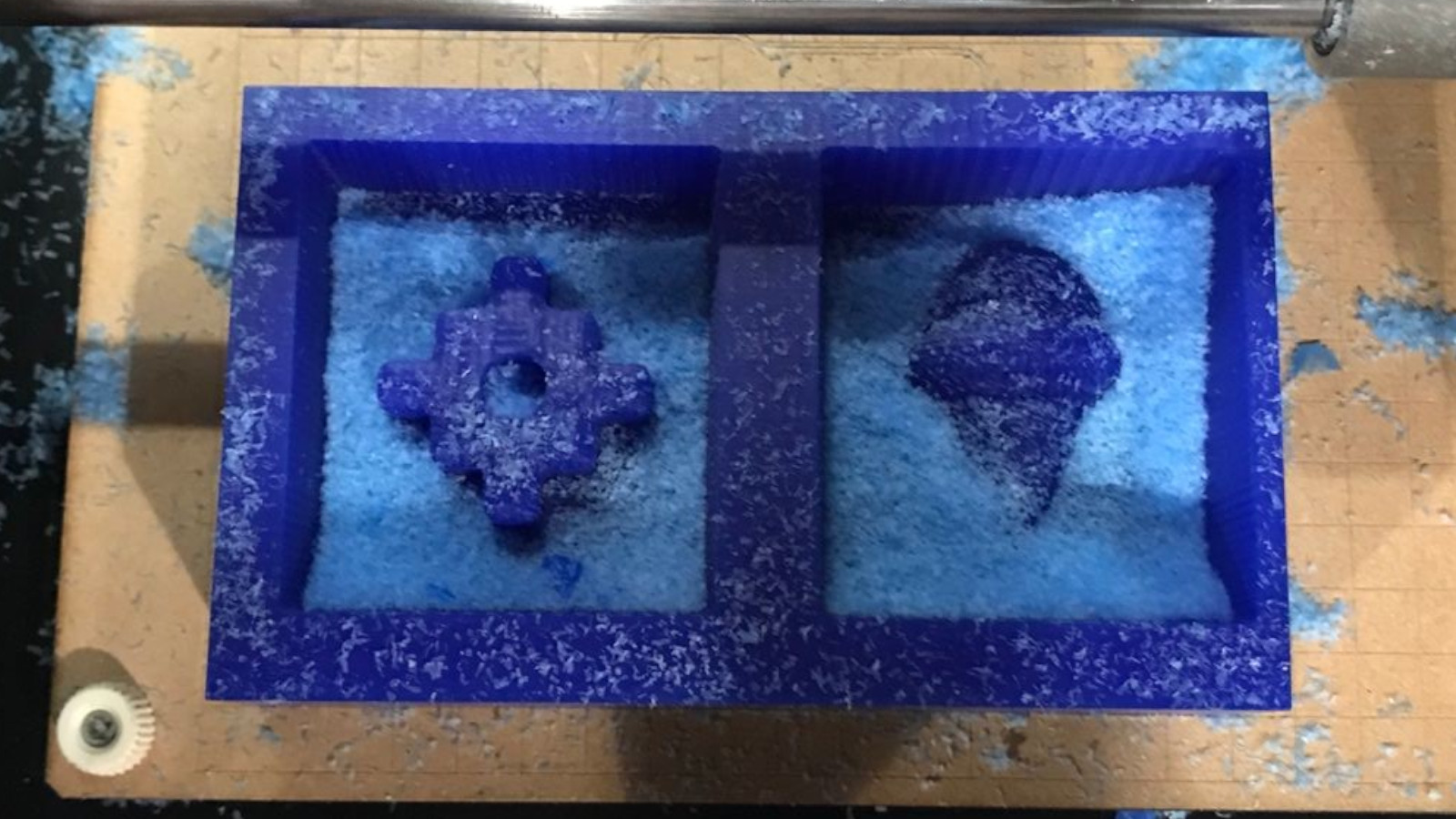
We configure the Triangular model in ArtCam, and we send the machining work but this time we choose the Raster option.
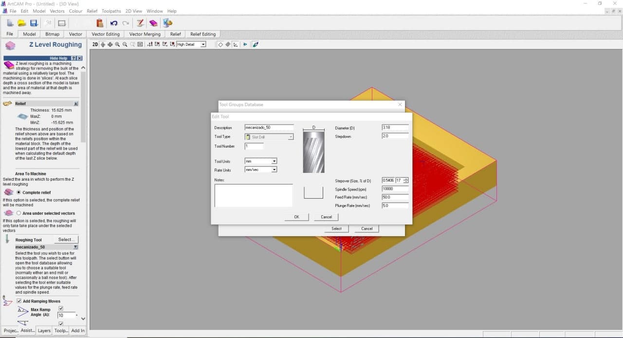
Tool Setting ArtCam
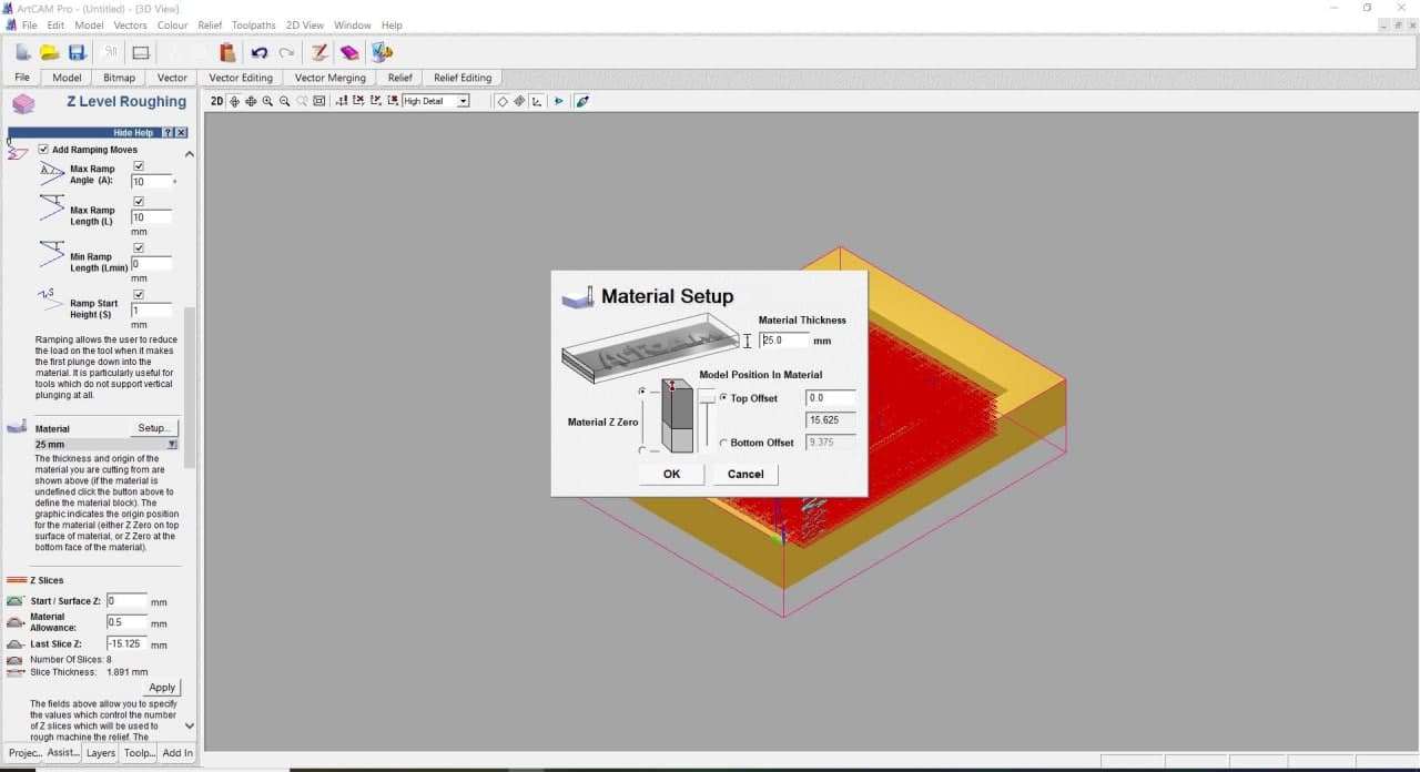
Material Setup ArtCam
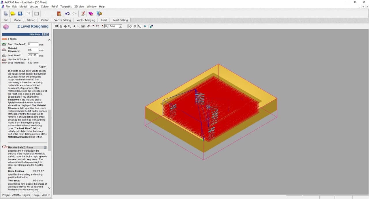
Parameters Machine Safe
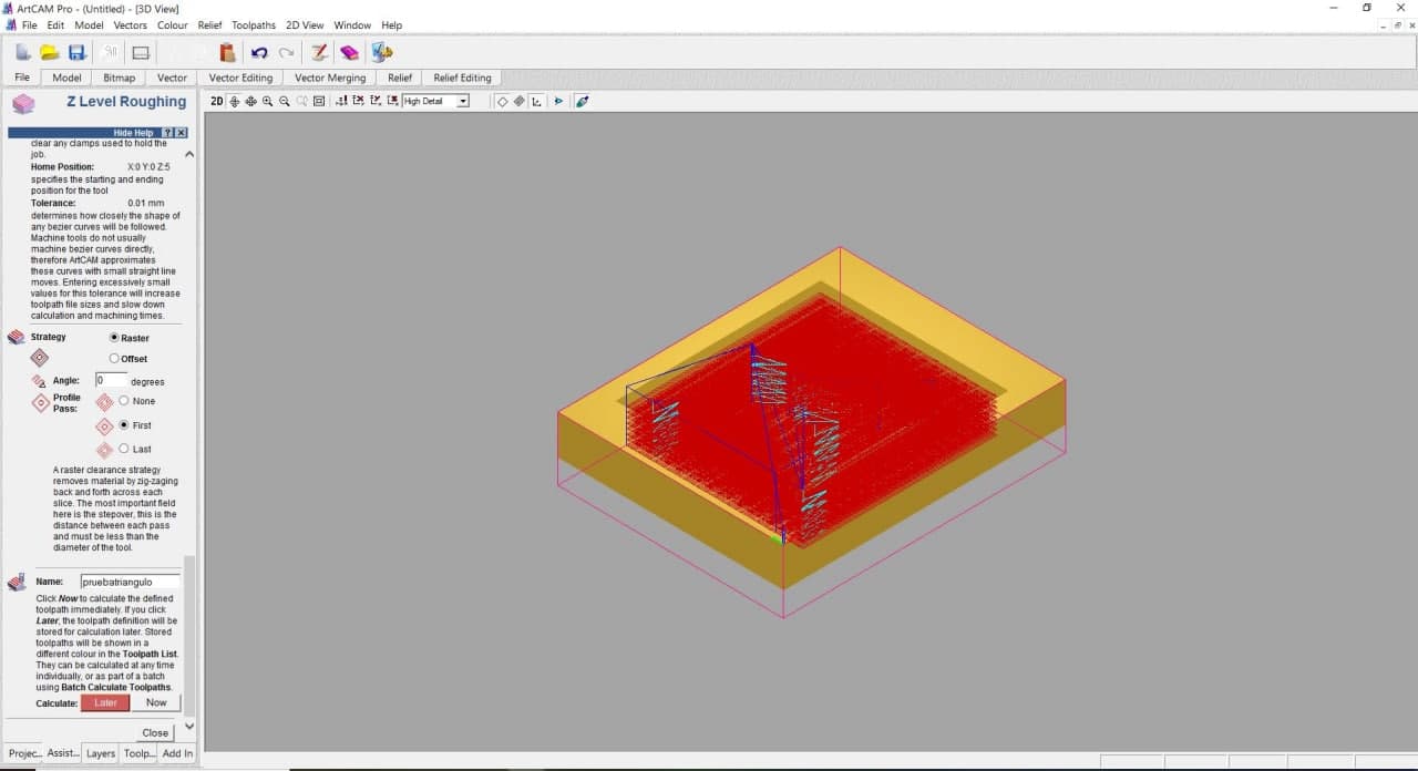
Raster milling & Now Calculate
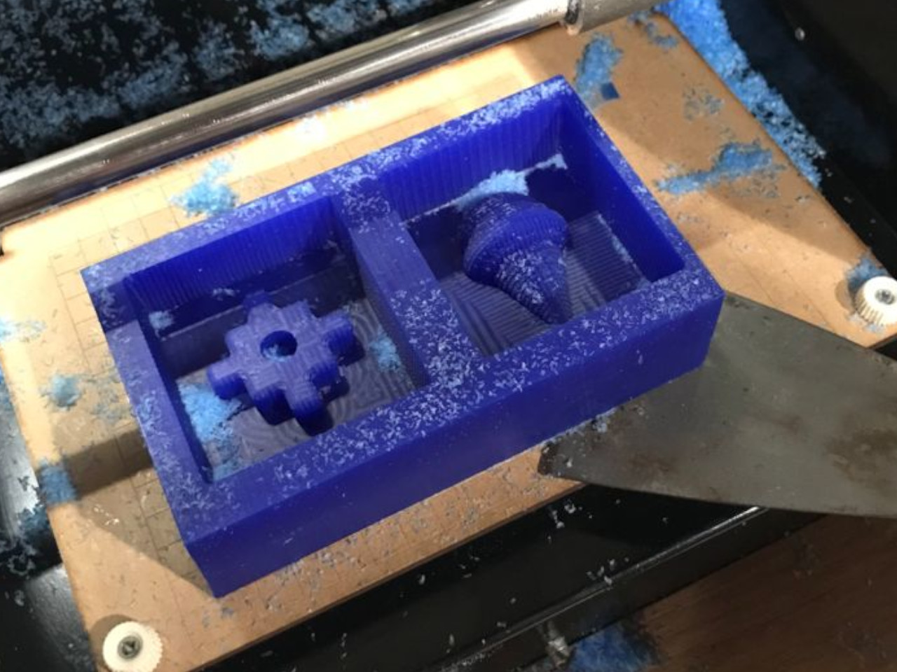
The result of this test mold was not what was expected either. The model was also out of phase on the X / Y axis. We saw how the machine works at different depths, and we noted the following: We must leave at least 1cm of edge for our wax molds. A centimeter thick at the bottom would be ideal.
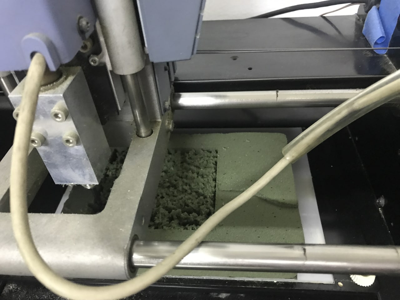
Triangle mold machining process
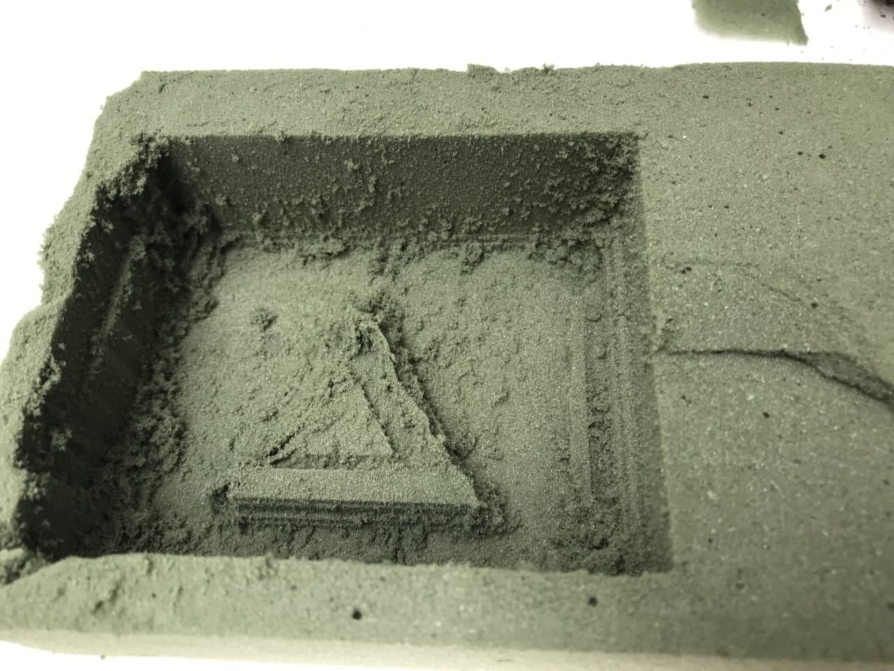
Triangle mold machining finish
MaterialsTesting
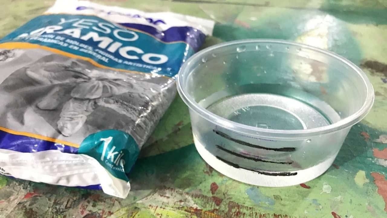
As we had two materials available, RTV SILIKAMOLD TYPE 6 + Catalyst Silicone rubber and ceramic plaster, we tested only these two.
We use 80gr of silicone and 2.0% of catalyst with respect to the amount of silicone. We waited 24 hours to unmold, and we had no bubbles. What didn't turn out very well were the "yases" that we put on. They were difficult to remove and it is highly unlikely that we will be able to reproduce such pieces.
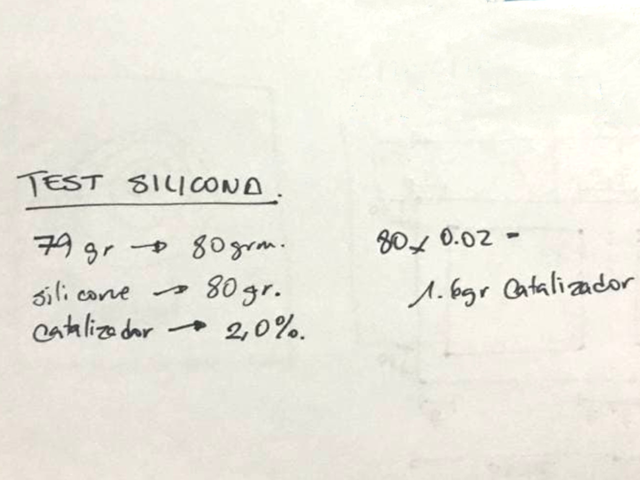
Mixing proportions
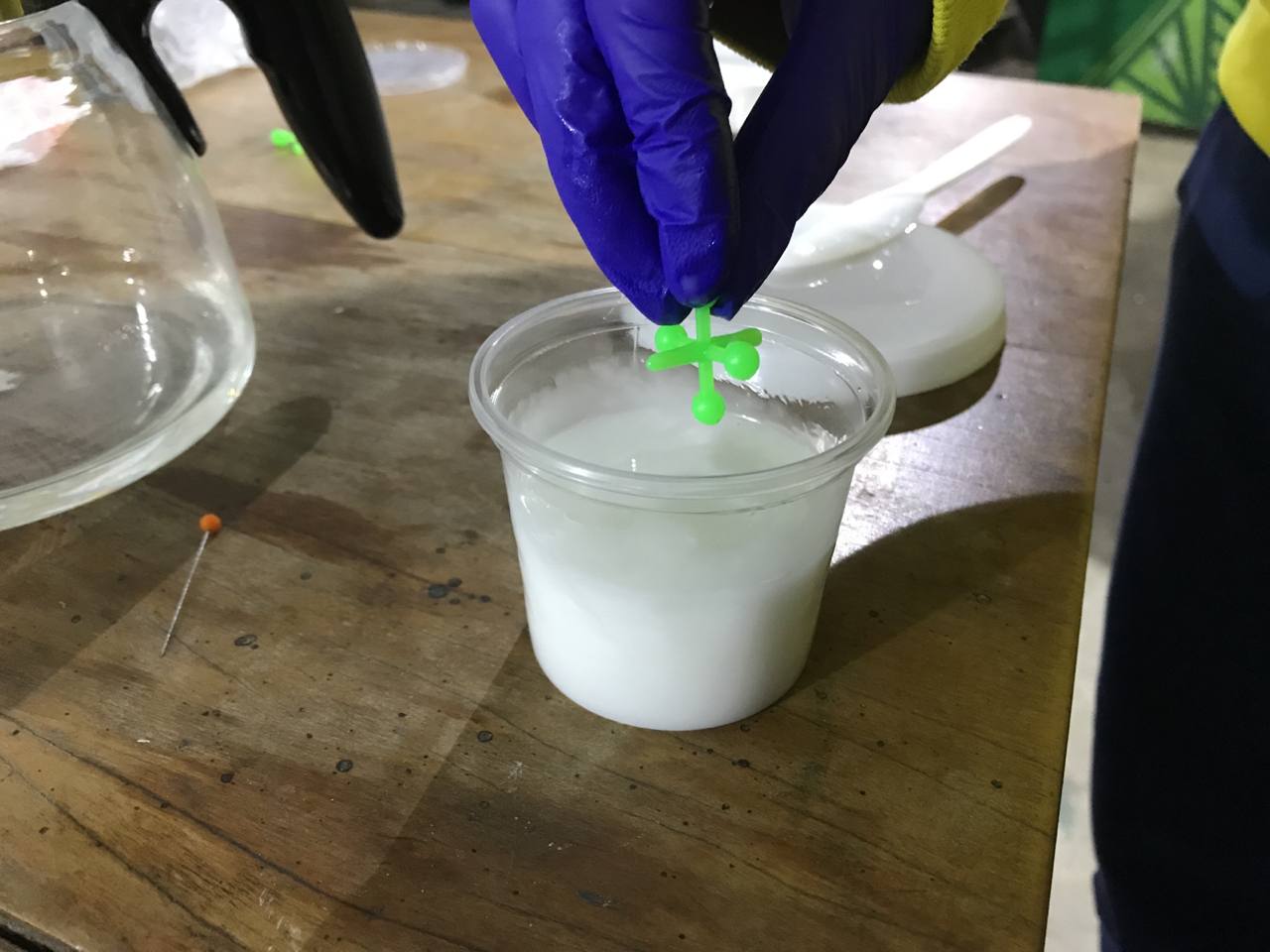
Silicone test with yases
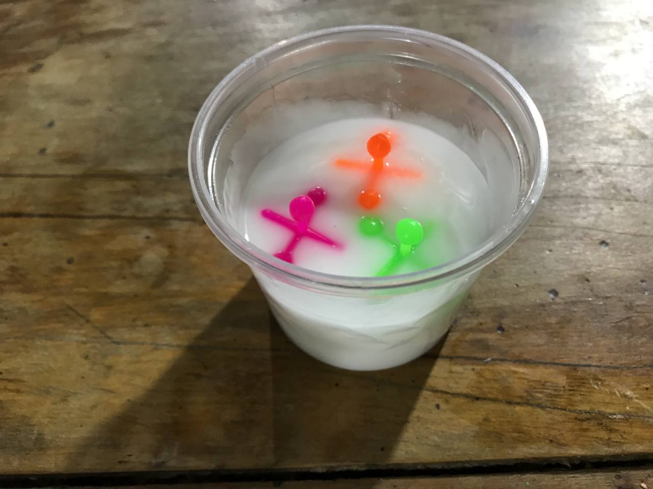
Silicone test with yases
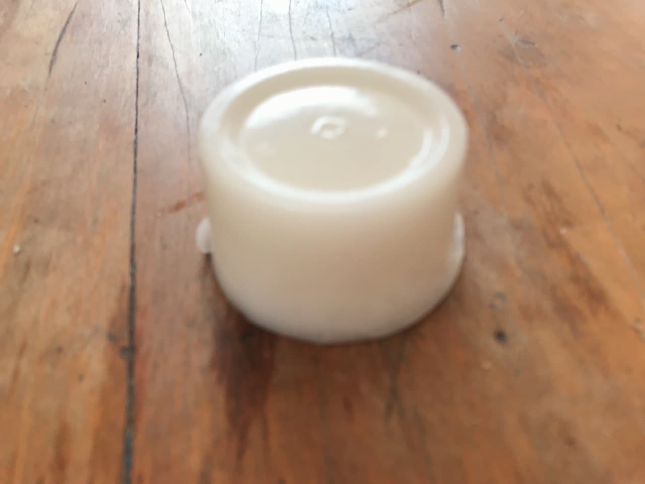
Unmold Silicone
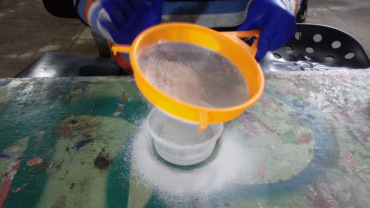
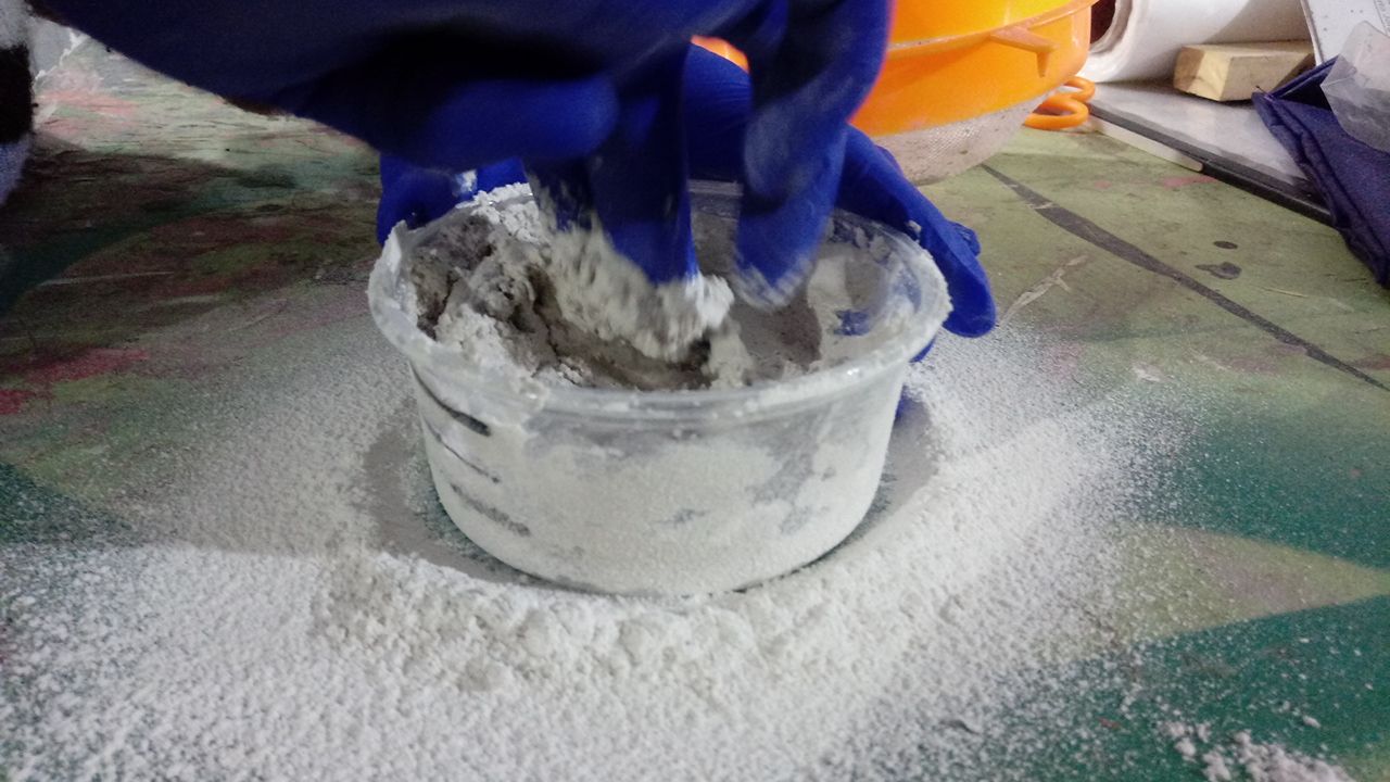
The recommended mixing ratio for ceramic plaster is 2 parts plaster to 1 part Water. We try to mix the plaster evenly with our hands to avoid lumps, but we do not pay attention to how quickly the plaster hardens. It is very important to put enough water in and always add the water first. Gradually add the plaster with a sieve and mix. Our mistake was trying to increase water while kneading. A disastrous result as you can see.🙄
Ceramic Plaster Test Proportions
Ceramic Plaster Test
Ceramic Plaster Test
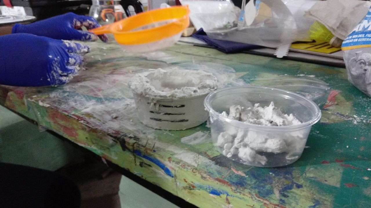
Ceramic plaster test failed
IndividualTask
After all the preliminary exploration, it's time to do the design. Inspired by Peruvian pre-Columbian designs, I decided to make the "Ghost Monkey" 🐒, a very old drawing of the Chancay culture. I love this design and I think I can make resin necklaces with this mold. But, this exercise required more complexity. It had to be a 3d mold and have rounded surfaces. For this reason, I designed a second mold: "The Ice Cream mold"🍧. I also fell in love with this one. An excellent exploration together with "Analuisa" in the lab that we have been implementing at the same time!
The first try:Ghost Monkey design
Guided by some tutorials that "GMH 000" shared with me, I made my design in the Fusion360 program. I was inspired by a monkey drawn on a ceramic from the Chancay culture, a pre-Inca culture, settled on the central coast of Peru. It is a very ancient civilization, between the years 1200 to 1470 AD. C.
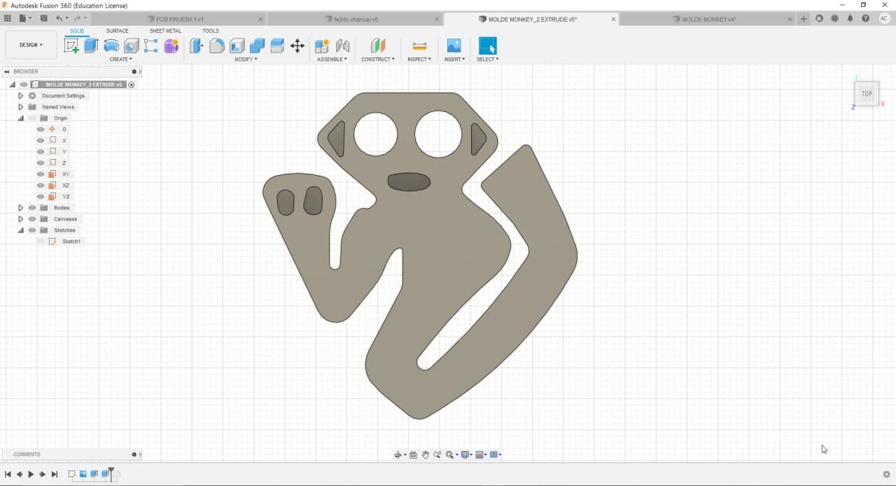
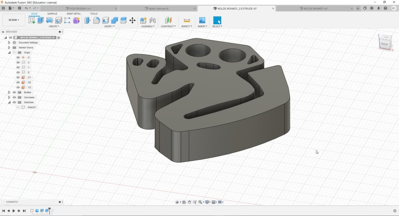
The abstraction of animals and shapes that they managed to capture in ceramics or textiles is very interesting. I was able to import the image into Fusion and then trace the shape, extrude it, and give it volume.
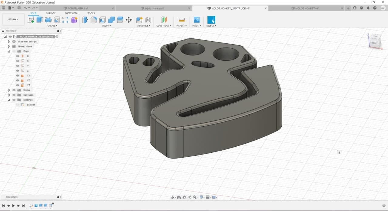
When rounding the edges, due to the proximity of some vectors to each other in the design, I could only make an edge fillet of 1 millimeter radius; therefore, the rounded part was very small. Probably if I had machined this mold, it would be all flat. On the real scale, it would only be perceived as an extruded shape, without any major complexity. I tried to round the same shape in Rhinoceros, but got the same response. So, use the "Ghost Monkey" to practice.
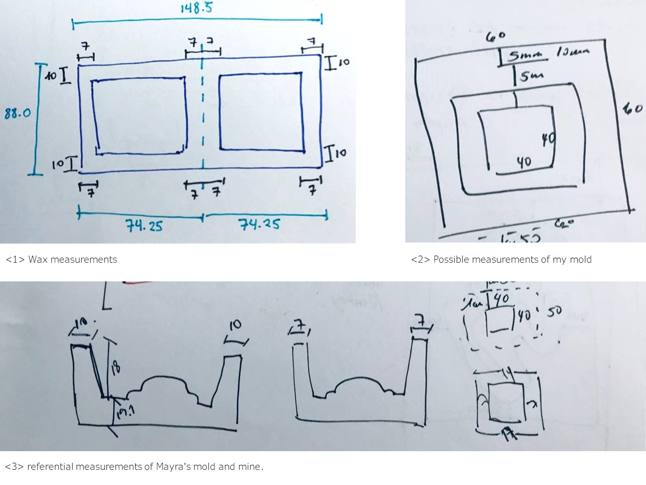
Design and measurements
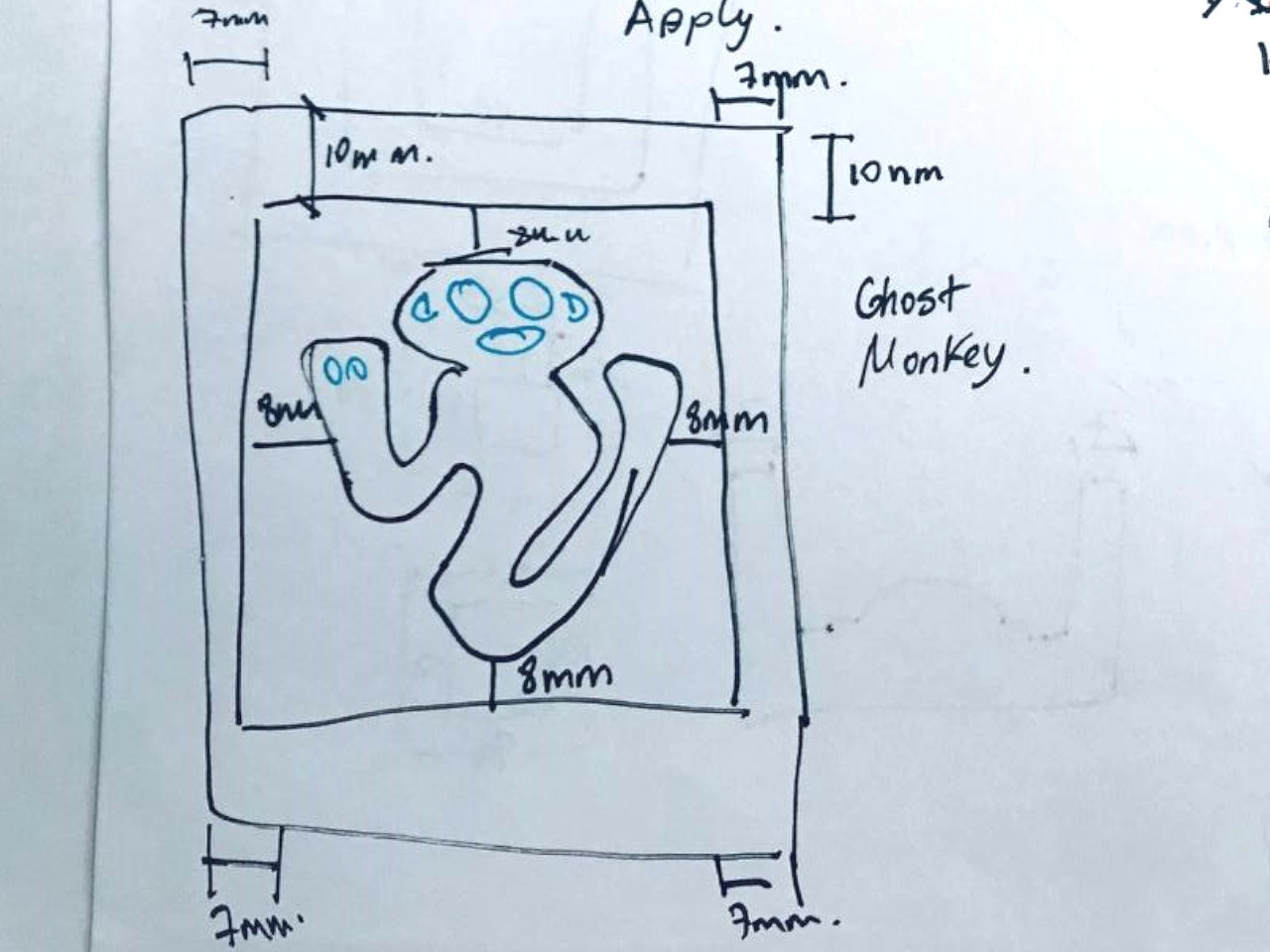
Design and measurements Ghost Monkey
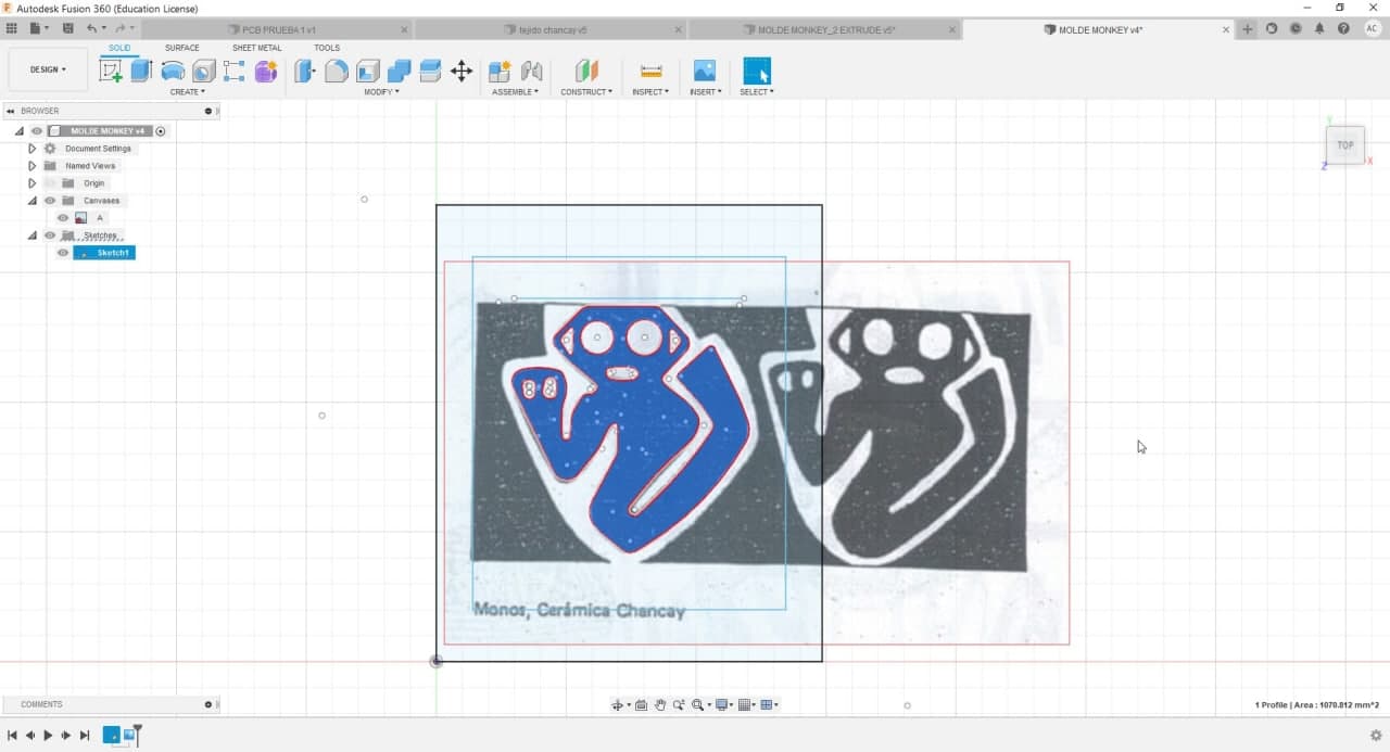
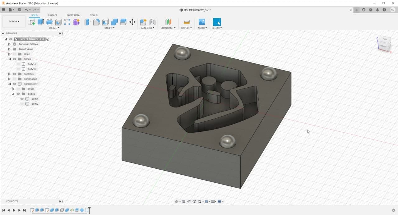
Ghost Monkey Mold in Fusion360
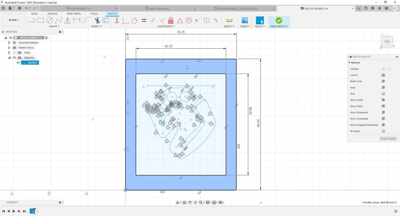
Ghost Monkey Mold in Fusion360
Ghost Monkey Mold in Fusion360
Ghost Monkey Mold in Fusion360
Ghost Monkey Mold in Fusion360
Ghost Monkey Mold in Fusion360
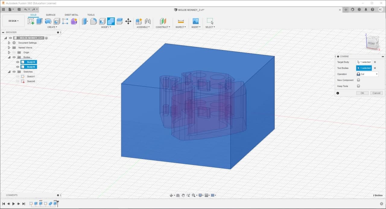
To continue the exercise, I made a top and a bottom part of the monkey mold. I added half spheres and holes to align the two parts. In addition, the holes where the silicone will be poured must be considered.
Ghost Monkey Mold in Fusion360
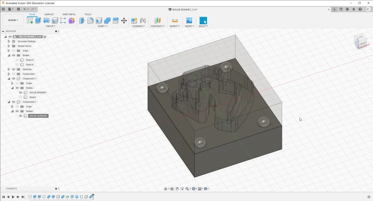
Ghost Monkey Mold in Fusion360
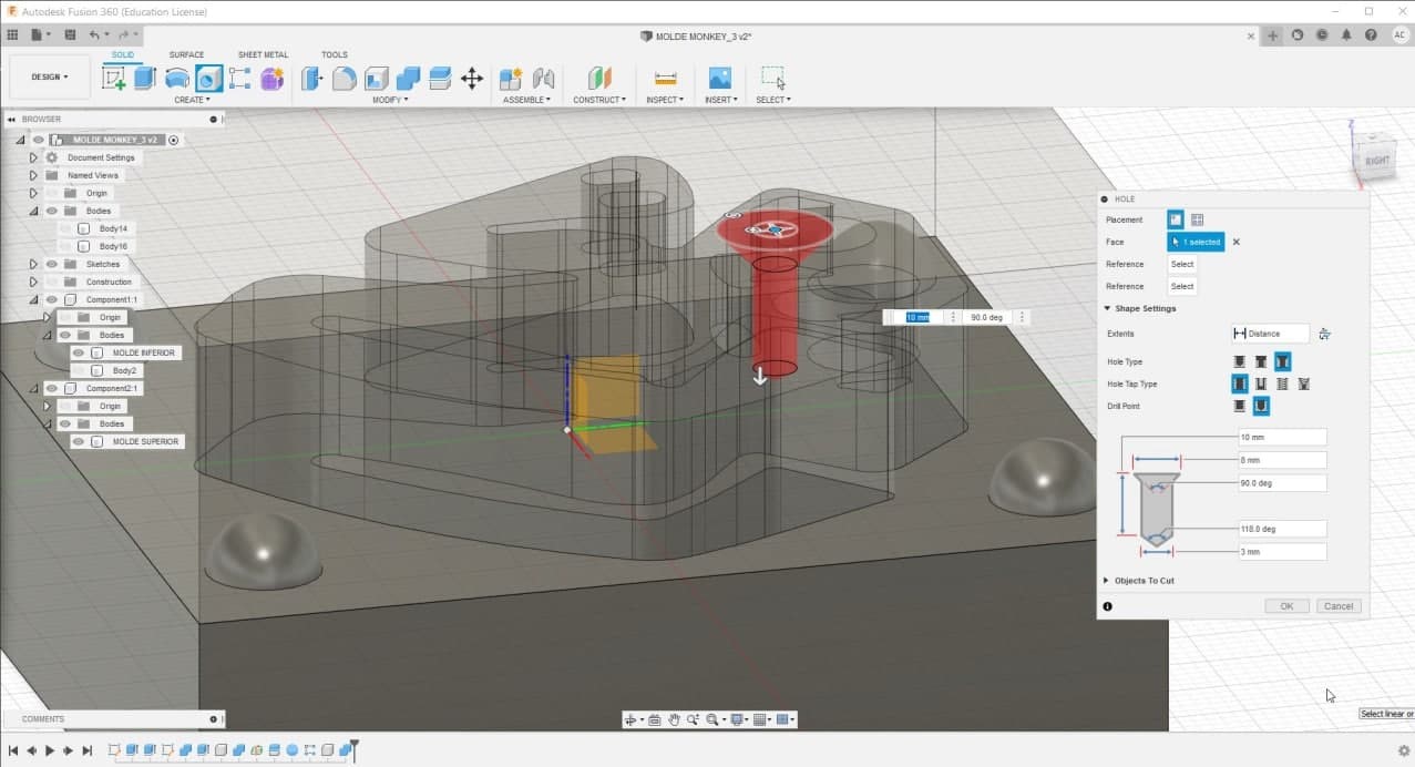
Ghost Monkey Mold in Fusion360
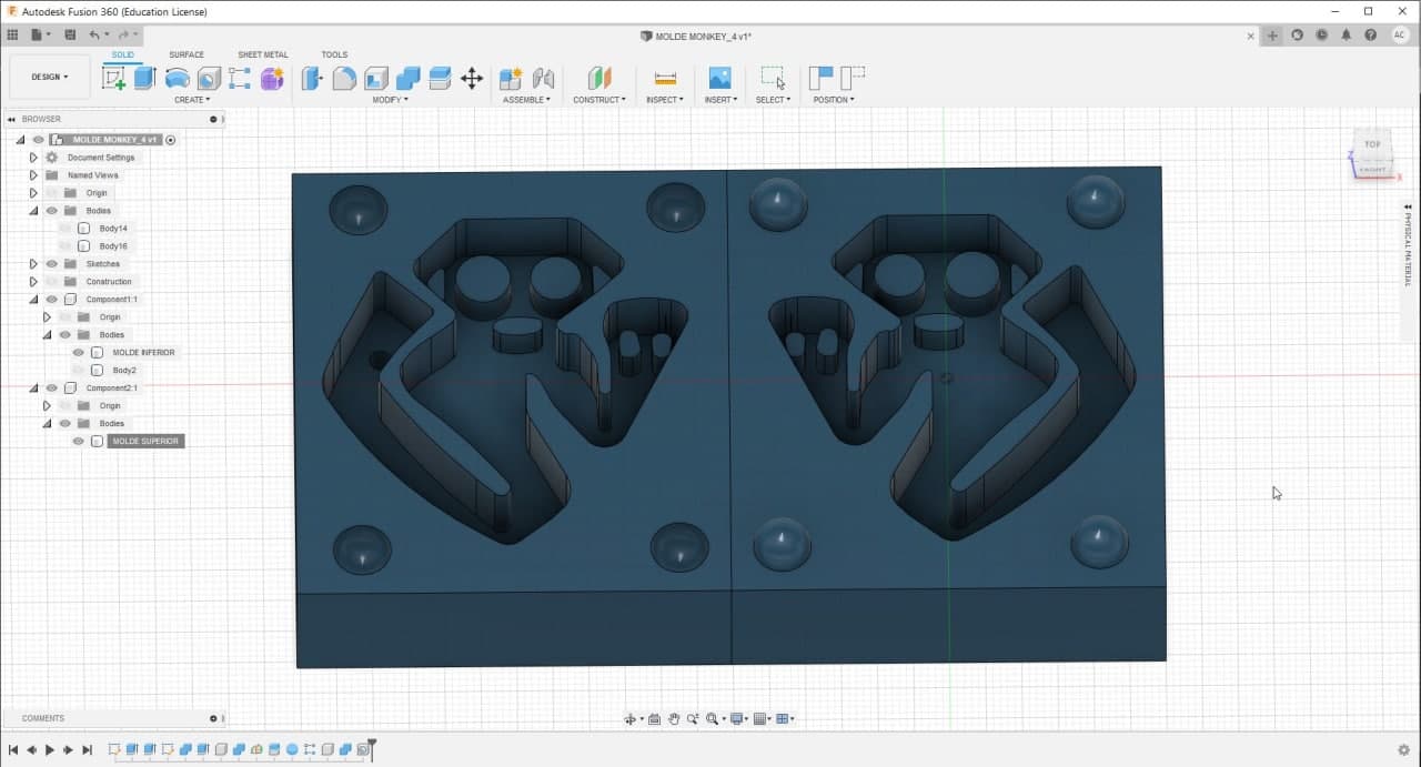
Ghost Monkey Mold in Fusion360
I also tried to make the monkey design in Rhinoceros, I used Fillet Surface, but I could only make 1mm radius of curvature. This is why I decided to change the design to an Ice cream.
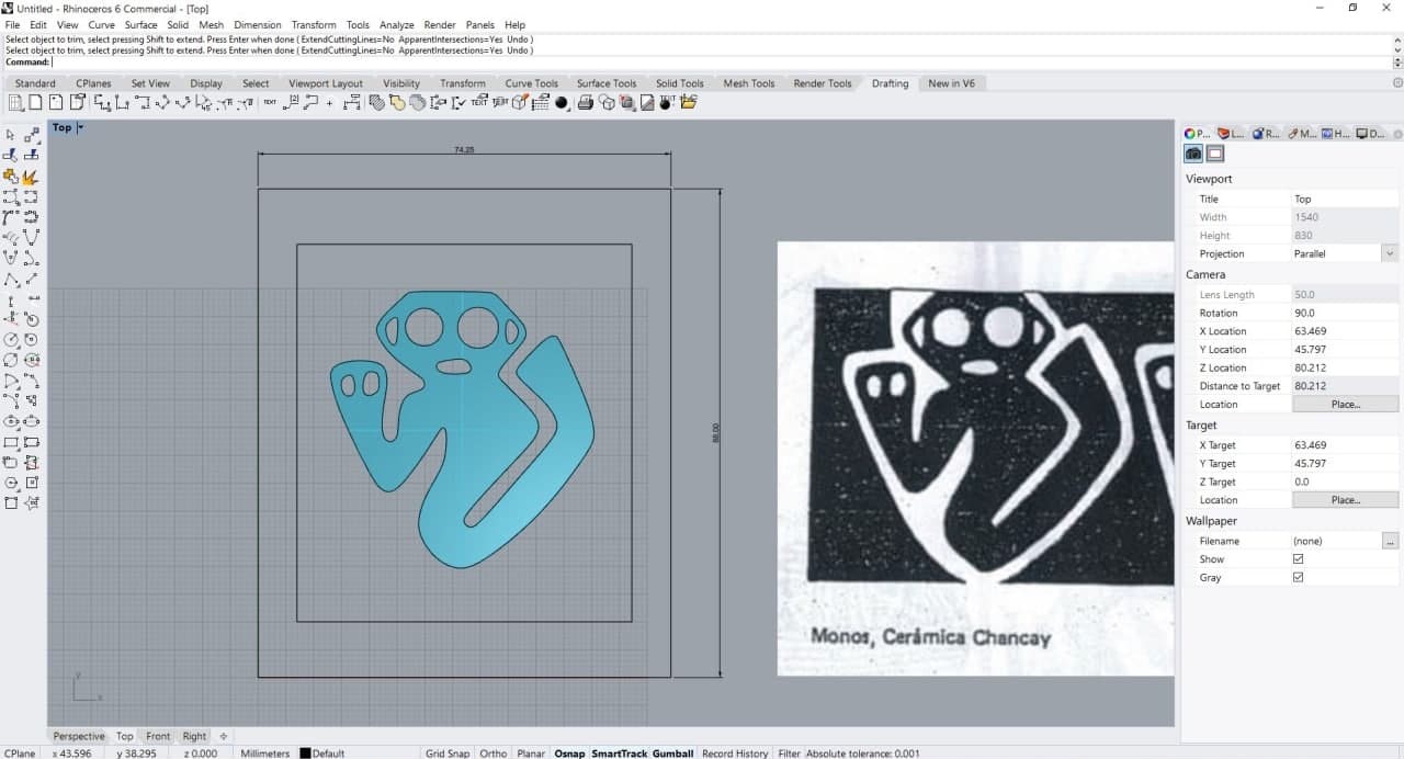
Ghost Monkey Mold in Rhinoceros
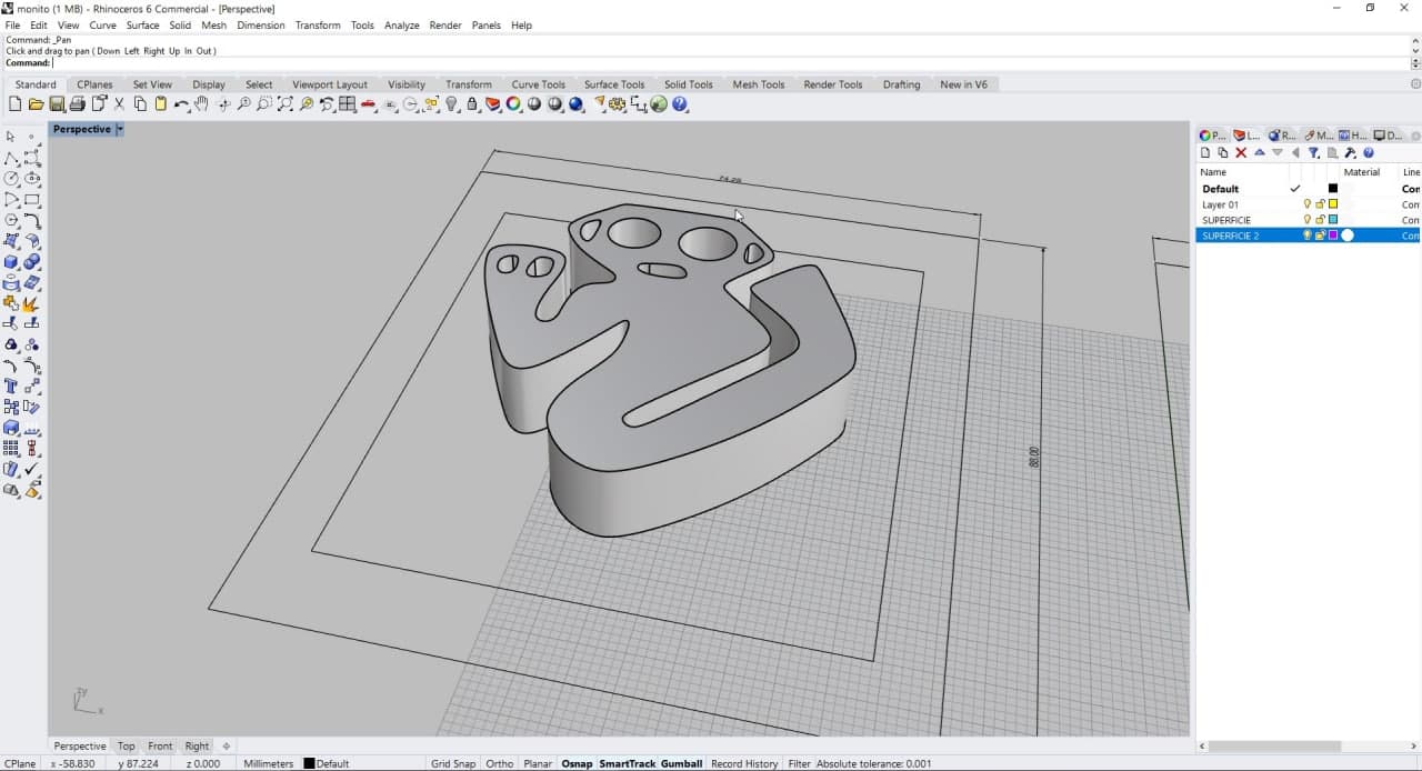
Ghost Monkey Mold in Rhinoceros
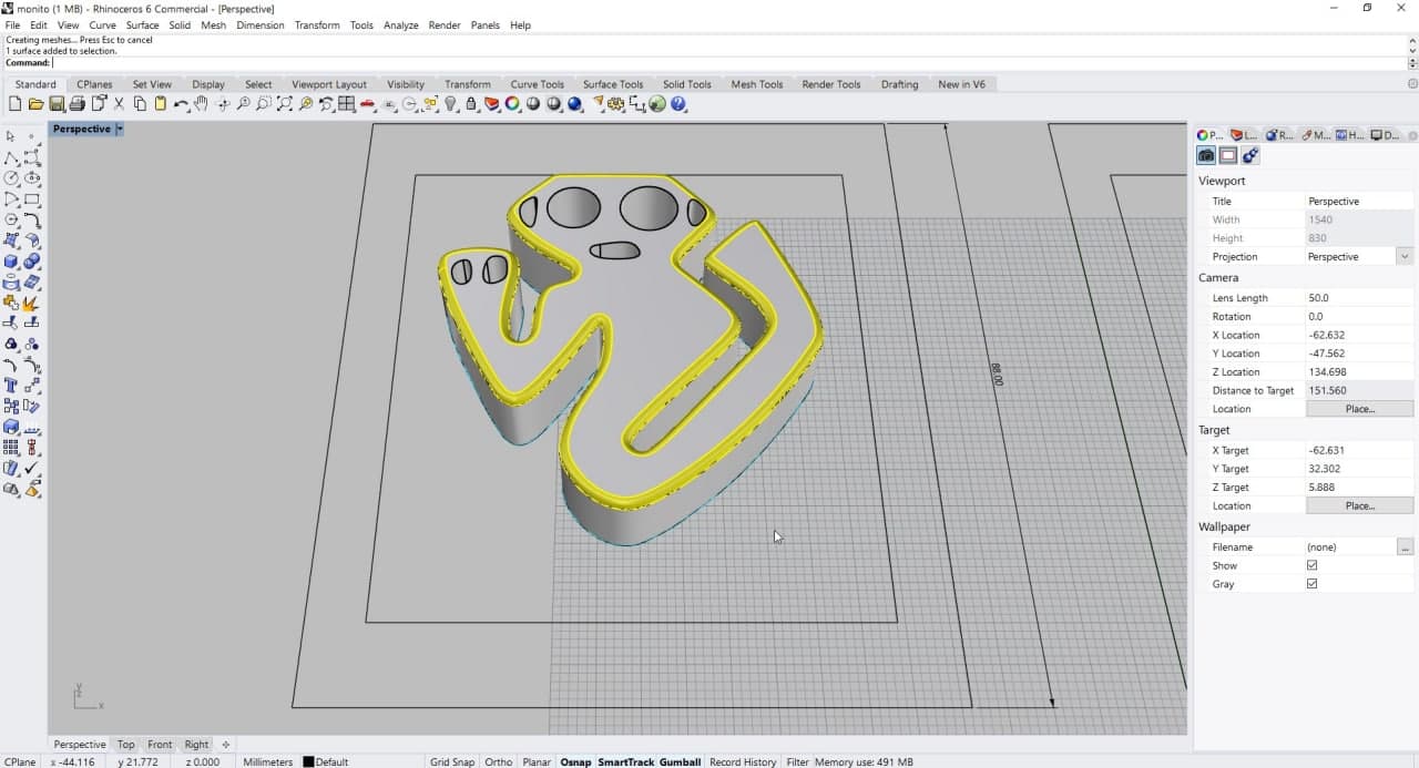
Ghost Monkey Mold in Rhinoceros
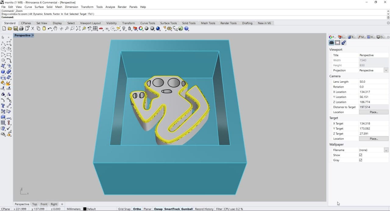
Ghost Monkey Mold in Rhinoceros
The finalDesign
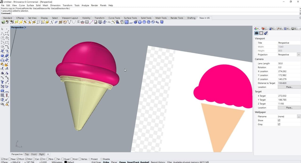
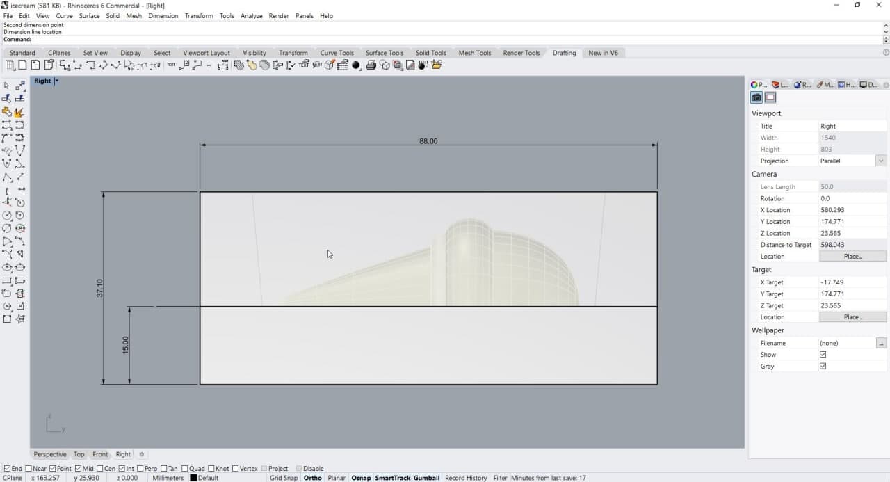
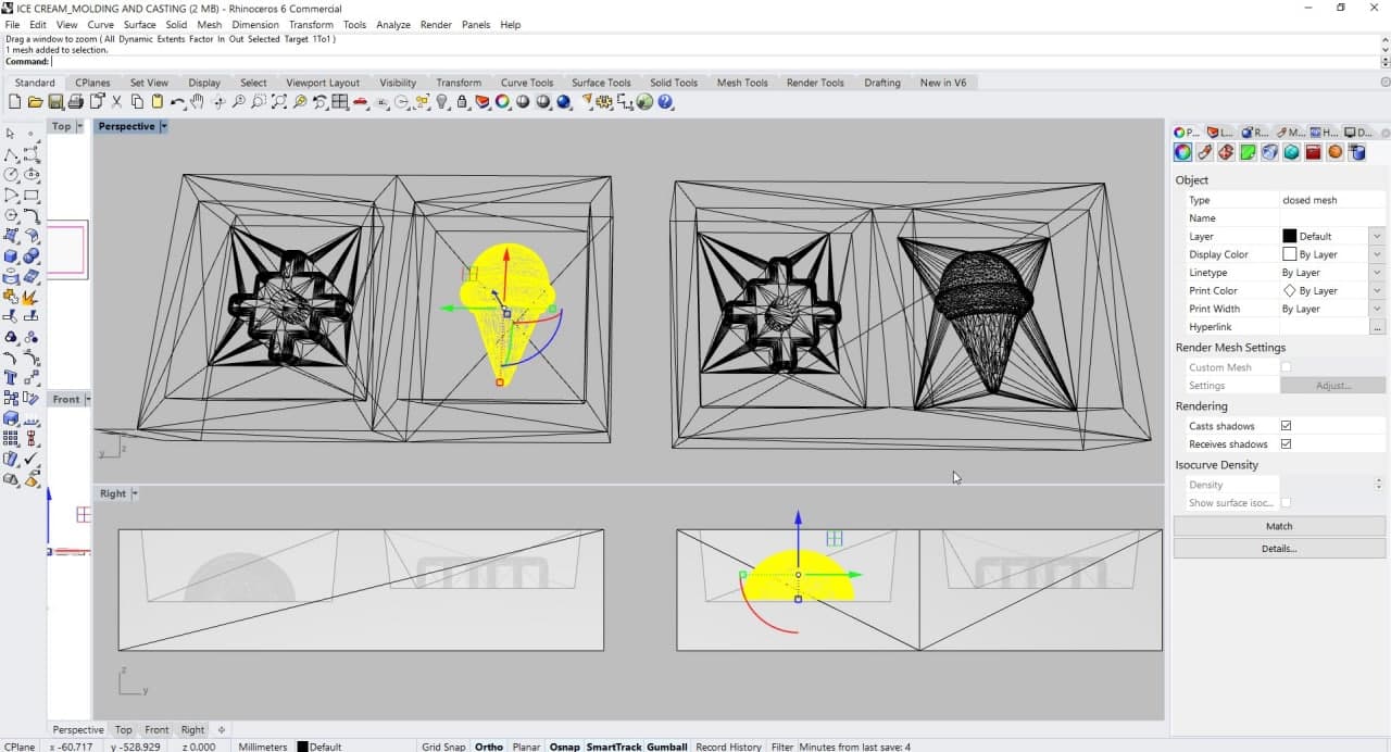
I chose an ice cream because of the complexity of its shape, I wanted to explore how the Modela worked with these types of surfaces. I made the design in Rhinoceros, traced an image and used the Revolve Curve command to get the half of the ice cream. The result was very good. Considering all the measurements previously explored, I designed the entire mold. I included the sloped interior walls. This helps to unmold the silicone much easier. It’s important to be aware that the mold to reproduce your shape is the silicone mold. The wax is a pre mold.
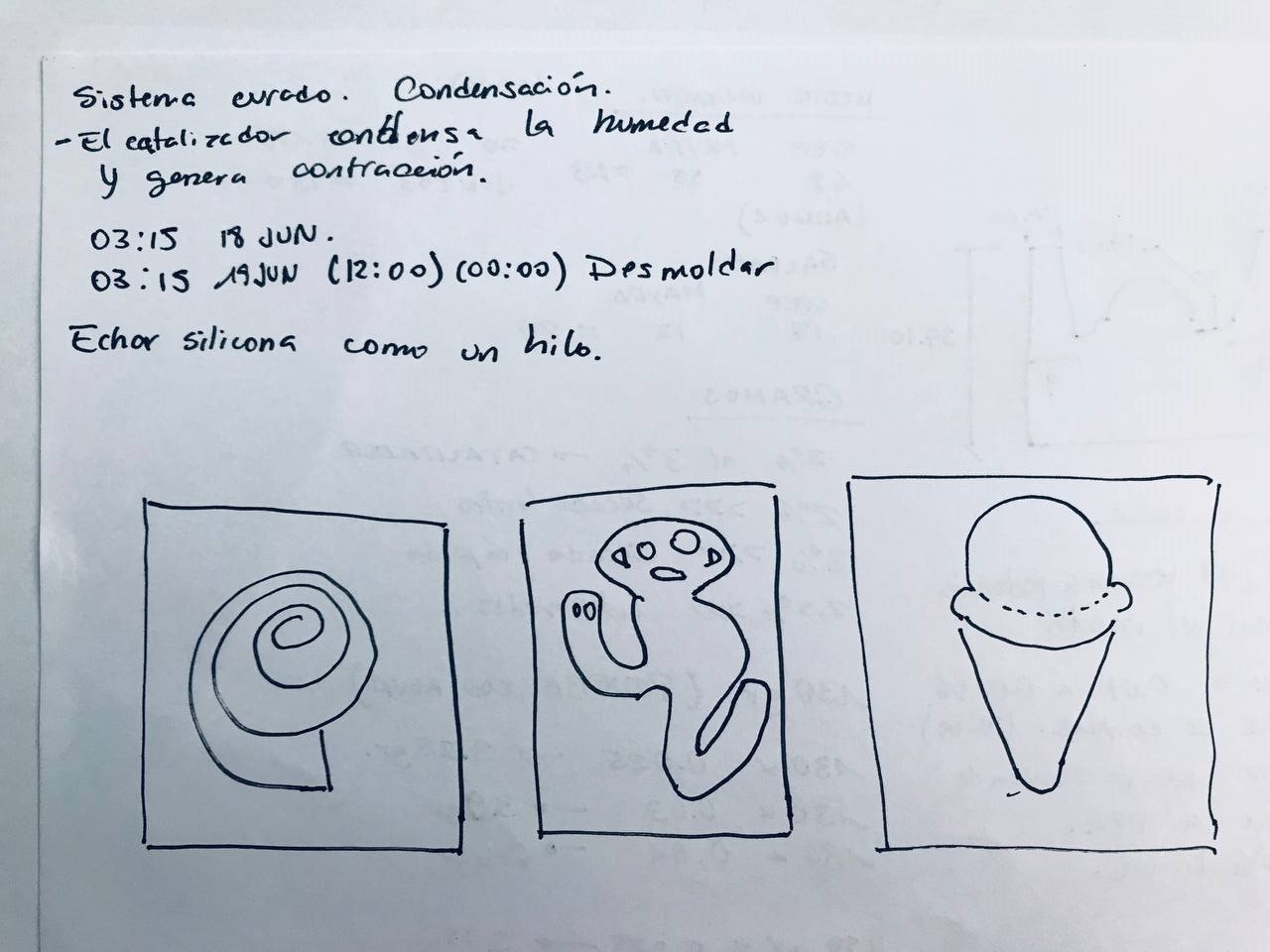
Notes to design
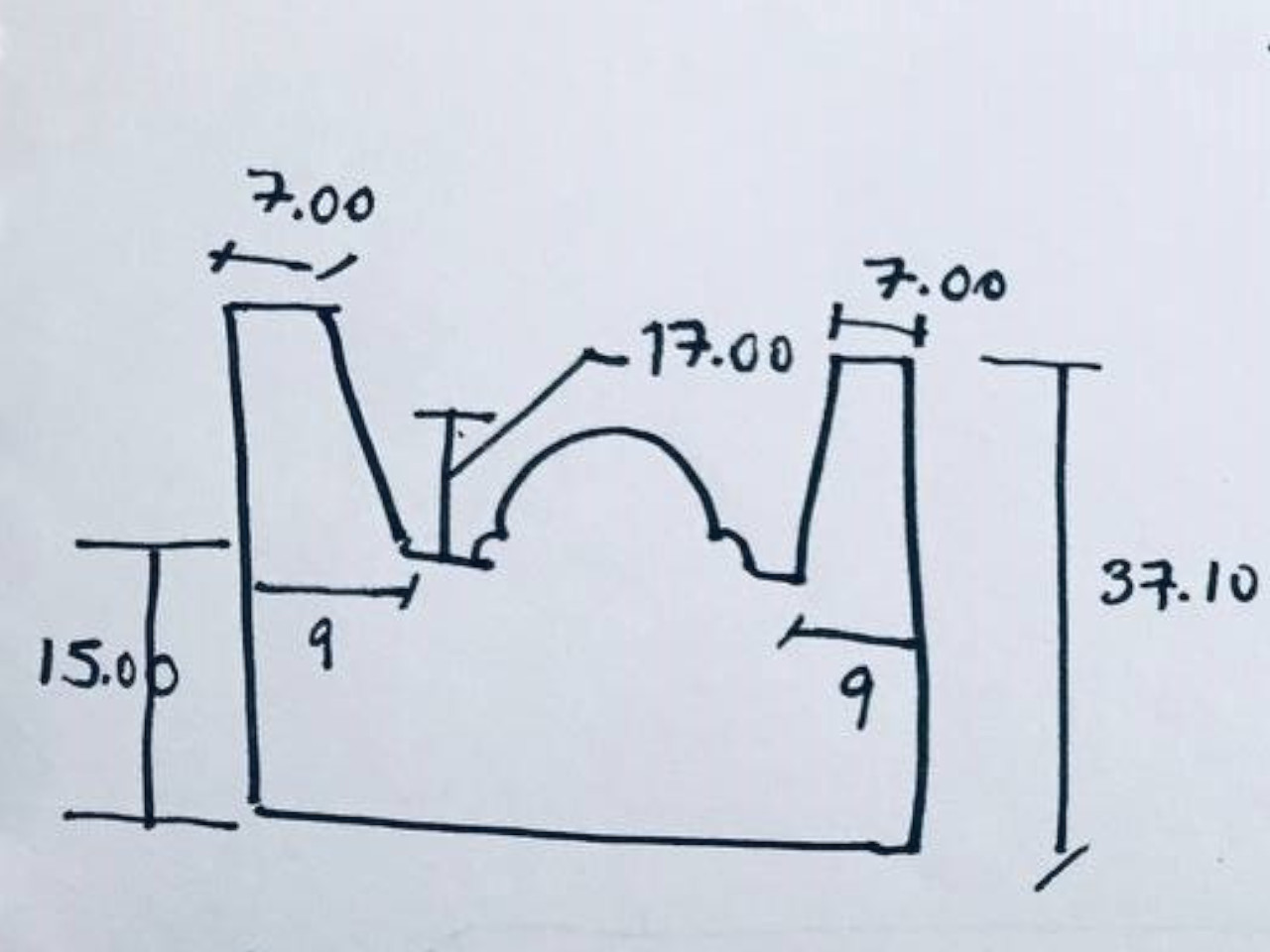
Notes to design
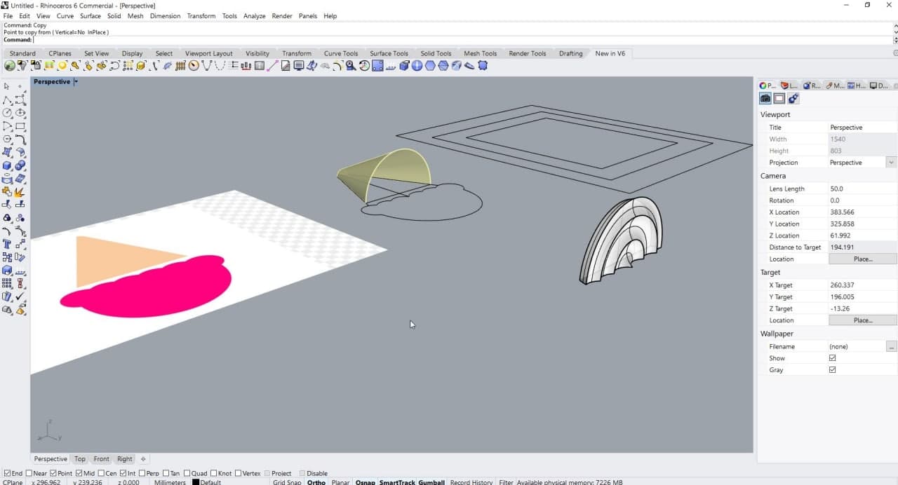
Ice Cream Mold in Rhinoceros
Ice Cream Mold in Rhinoceros
Ice Cream Mold in Rhinoceros
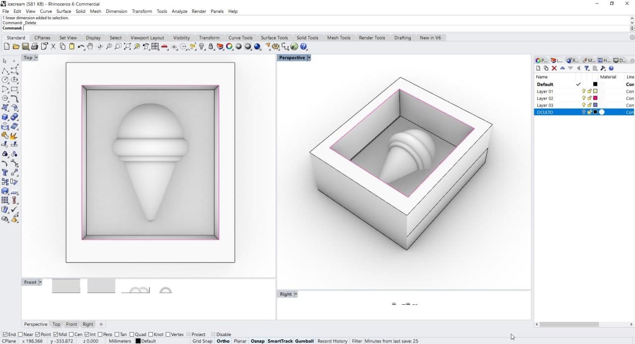
Ice Cream Mold in Rhinoceros
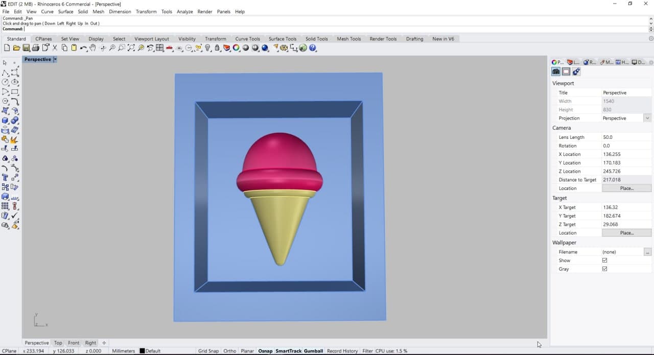
Ice Cream 3D Mold
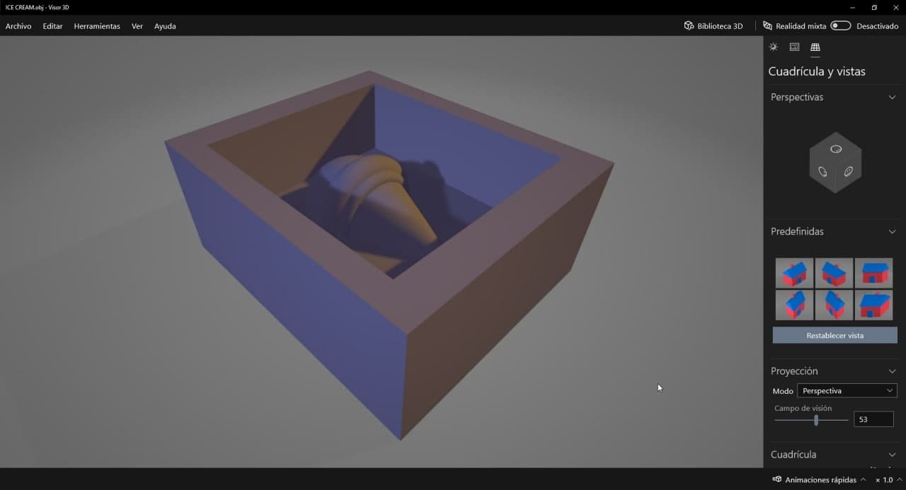
Ice Cream 3D Mold
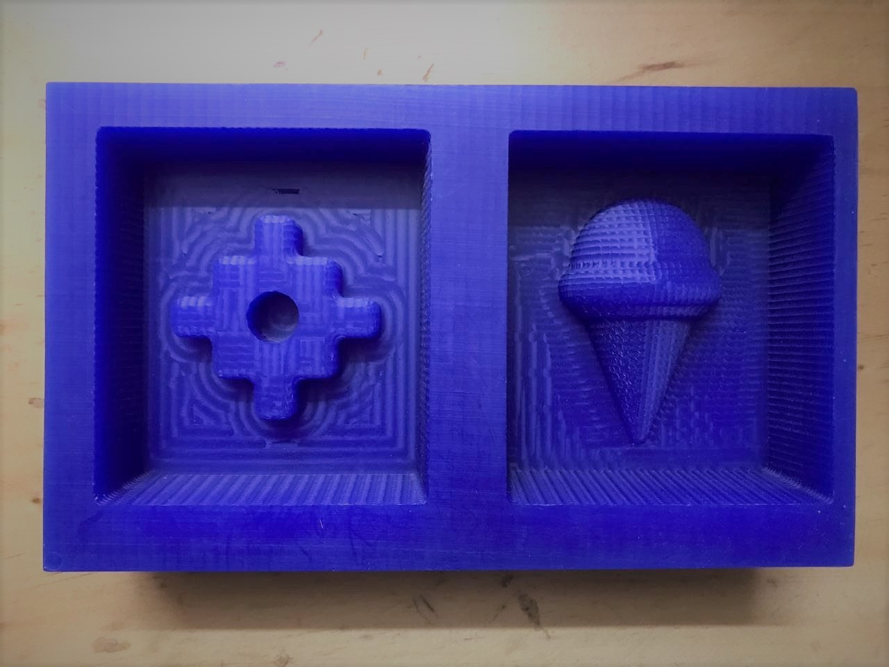
Joining the designs
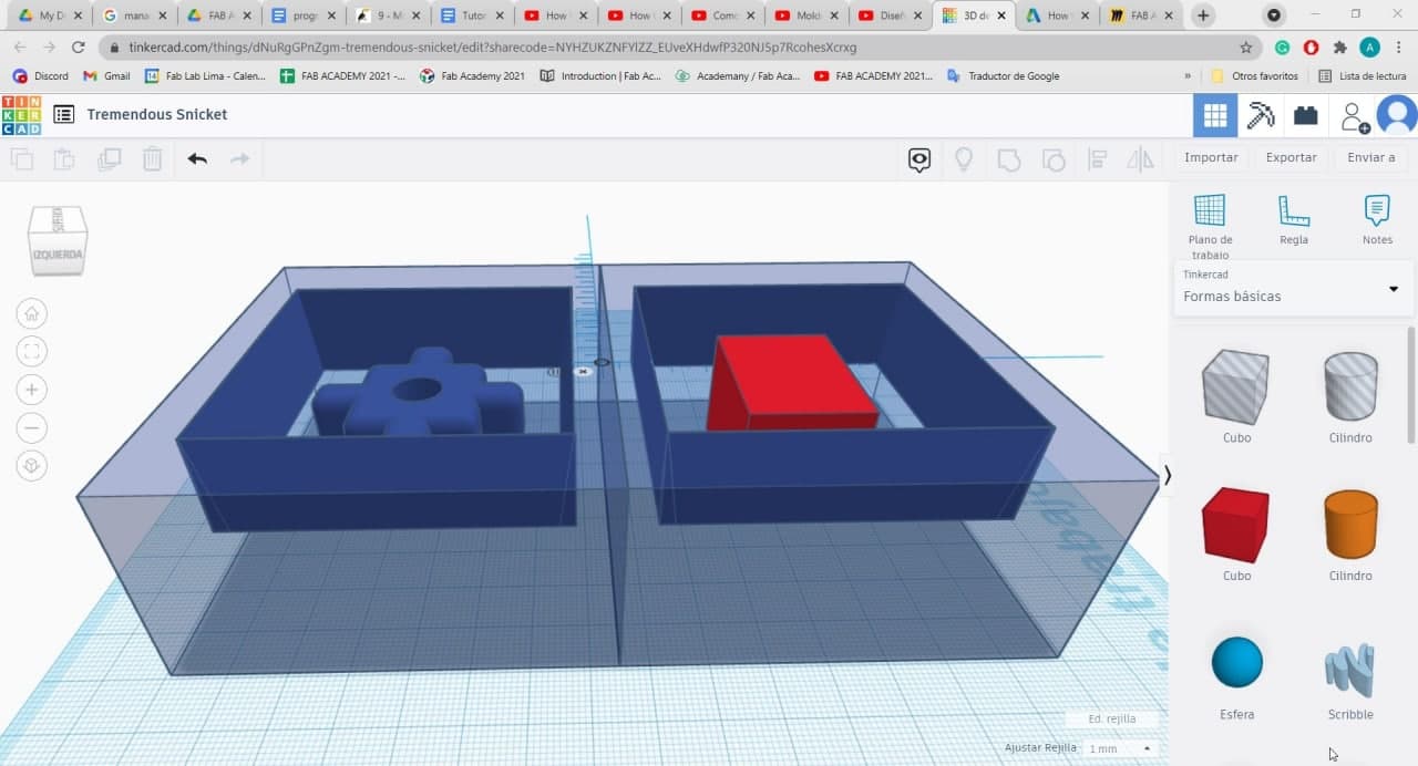
Optimizing the only wax block that "Rebecca" has and that she will kindly share with me. We decided to join our designs into a simple software: Tinkercad. The plan was that each one would make a one-sided mold. Then we import the designs in .STL format and put them together in an online file. It was quite simple, I recommend this method. Finally, we export the file in .stl format. We have a single block ready for machining!
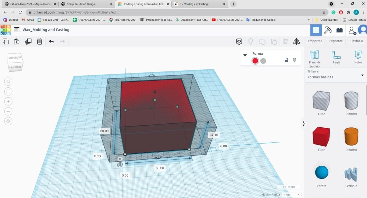
Measurements in Tinkercad
Tinkercad - Joining our molds
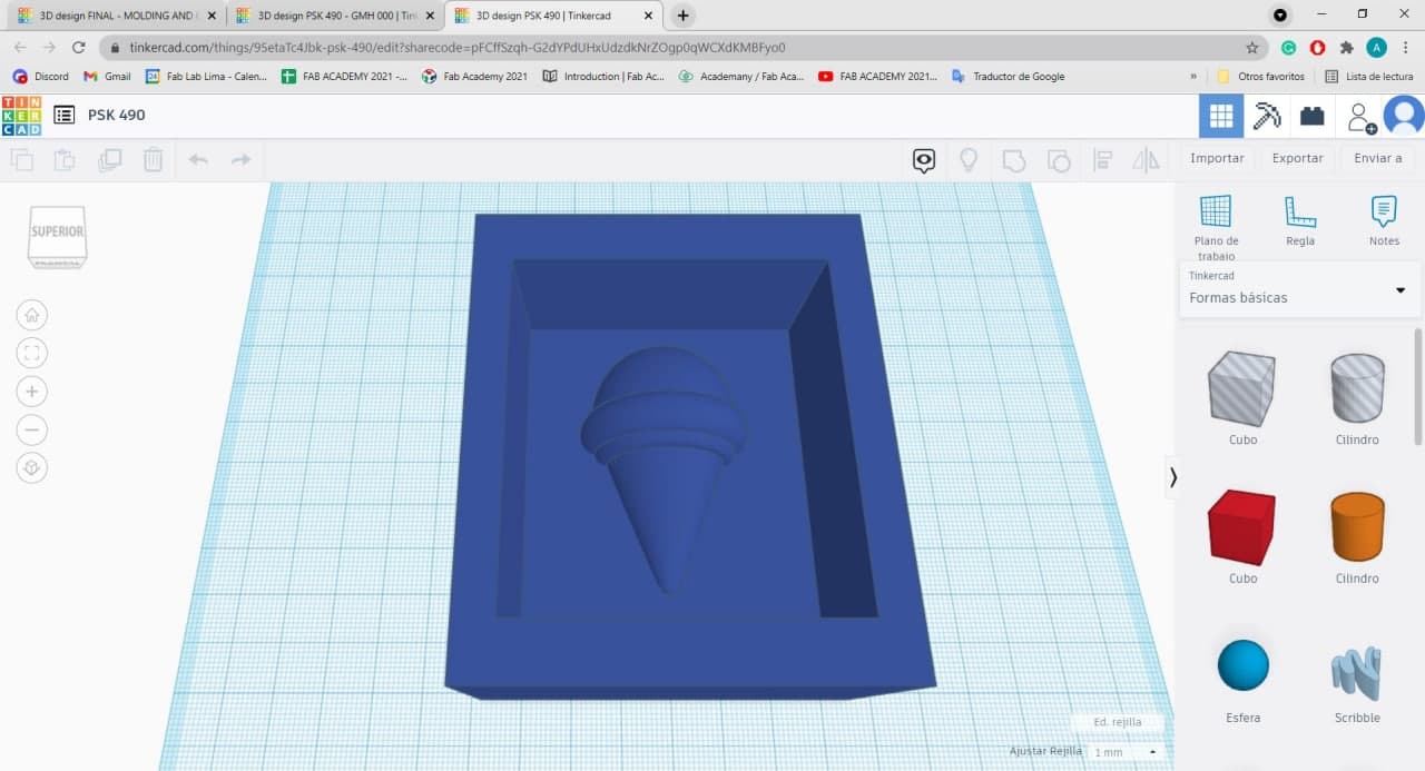
Tinkercad - My mold
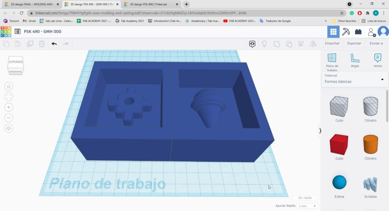
Tinkercad - Mold together
It's necessary to check your file in a program to see if everything is working correctly. When we opened the whole mold file in Rhinoceros after importing from Tinkercad, we discovered that the ice cream was flying. And it hadn't really merged, so we corrected it.
Checking the mold
Millingthe Wax
It's time to move on to the milling process. Thanks to Fab Lab Esan and its instructors for allowing us access to equipment, we were able to carry out this part of the task. We use the Modela MDX-20 together with the Fab Modules to achieve the machining of our wax block. Together with Mayra, we successfully achieved this goal and now we have a joint wax mold ready to go to the "Casting" stage.
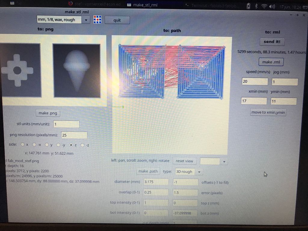
Modela_FabModules_parameters
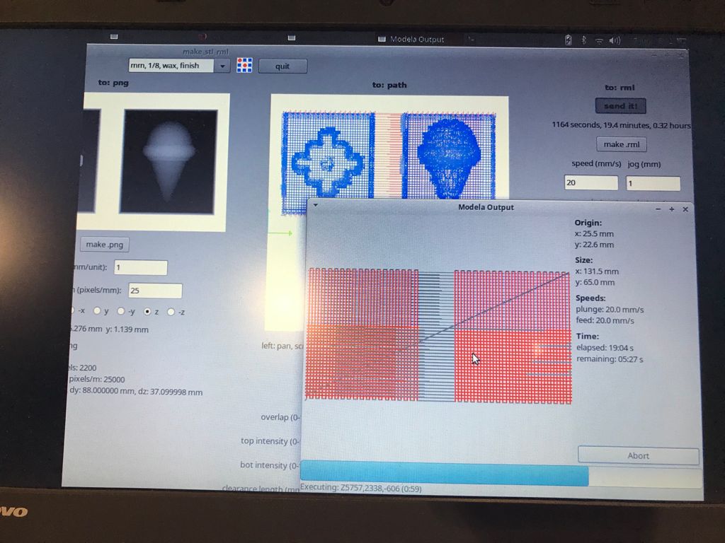
Modela_FabModules_parameters
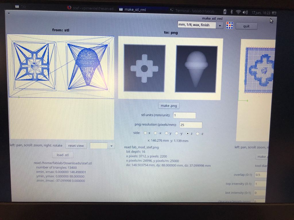
Modela_FabModules_parameters
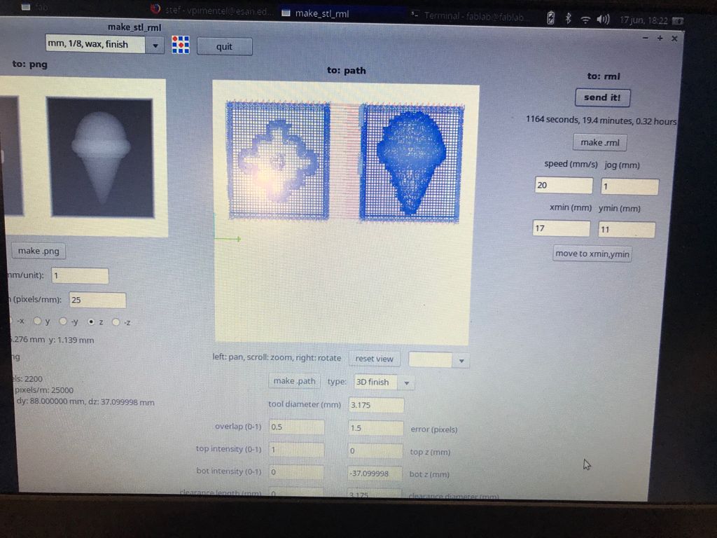
Modela_FabModules_parameters
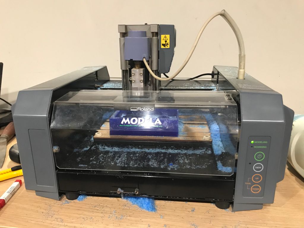
Modela Mdx-20 Milling Process
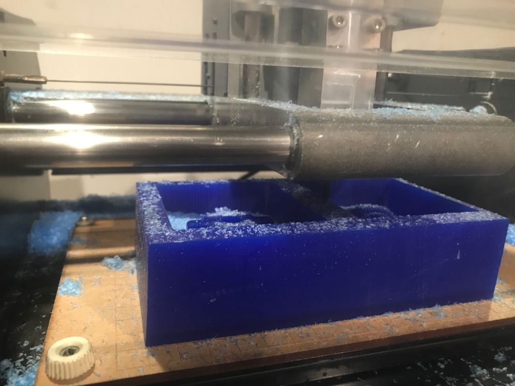
Modela Mdx-20 Milling Process
Modela Mdx-20 Milling Process
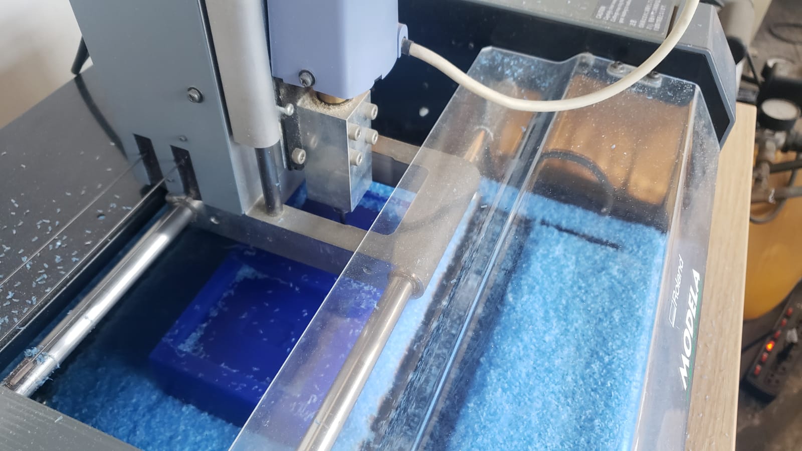
Modela Mdx-20 Milling Process
Modela Mdx-20 Milling Process
Modela Mdx-20 Milling Process_Final
Wax Mold
Wax Mold
TareProcess
Before any casting in Silicone, we first had to measure the amount in grams that we needed to prepare. It’s important to take the weight of the container away from the weight of the material being weighed on the scale. For this, we first weigh an egg. Then we weigh the empty container, press the button that says "Tare" and the scale returns to 0, we put the egg into the container and the scale gives you the weight of the egg and subtracts the weight of the container. In this way, we obtained an accurate weight.
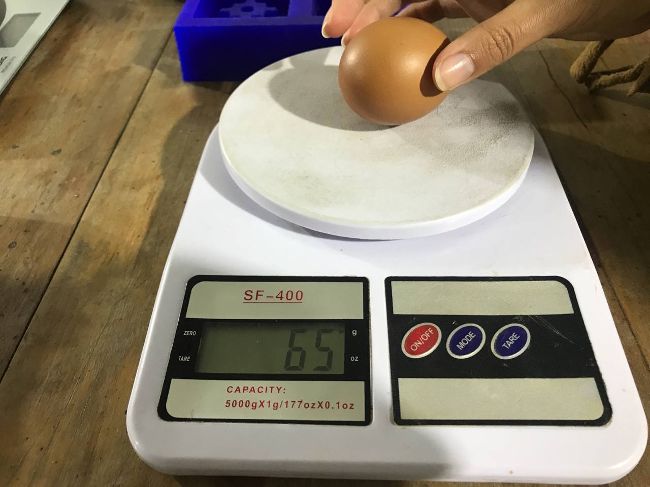
Weigh the egg
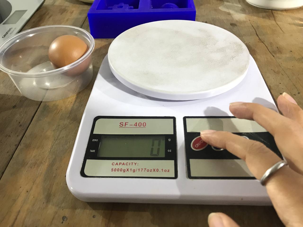
Start the scale
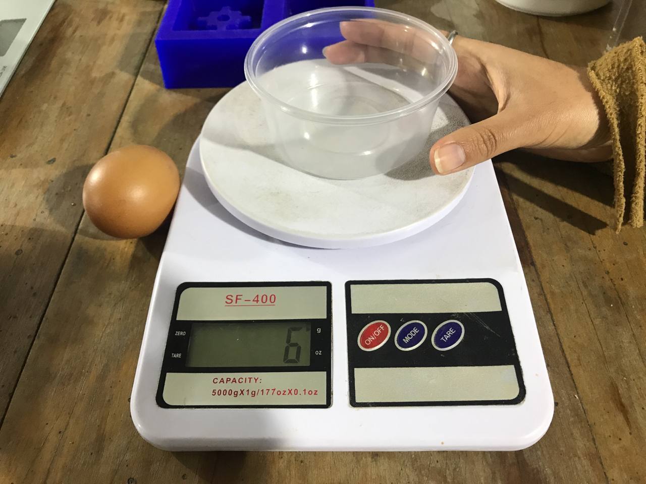
Weigh the empty container
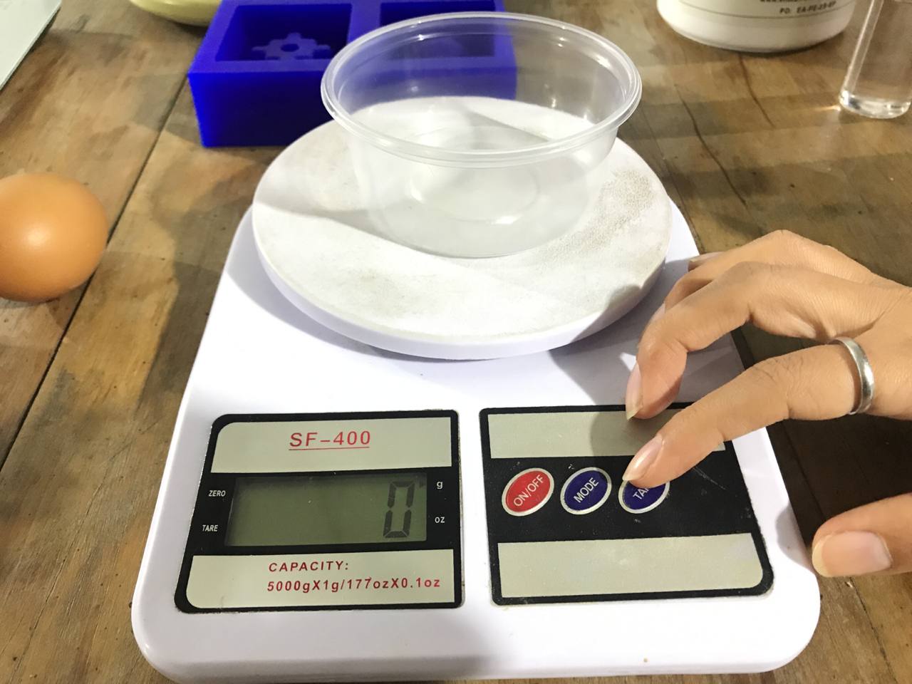
Press the button: Tare
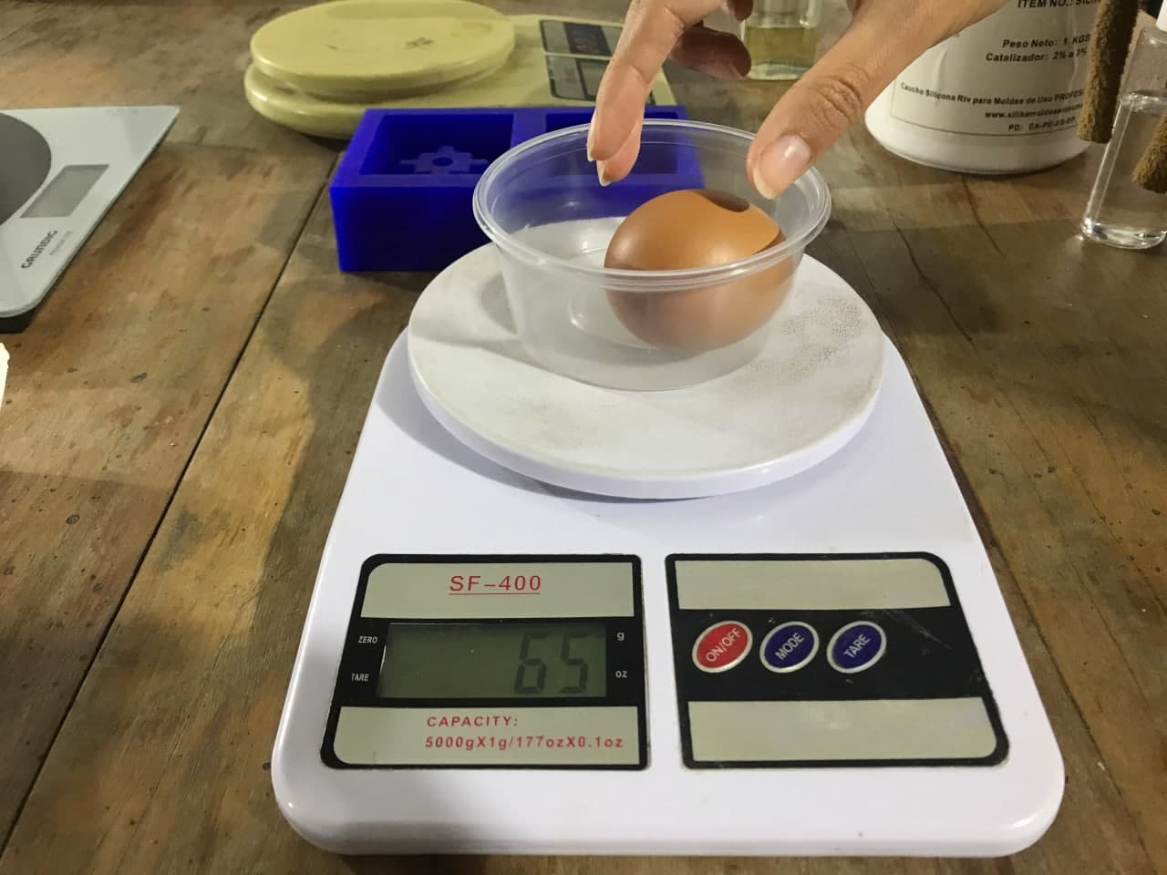
Weigh all
Pre-CastingProcess
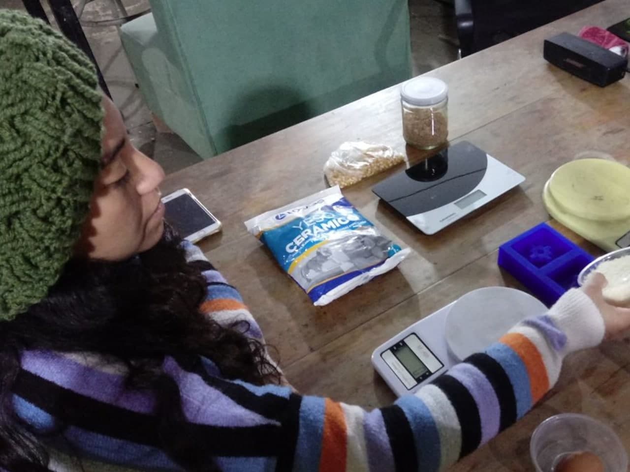
After learning how to use the scale correctly, we decided to measure the amount of grams that we needed with different elements; Rice, Wheat bran and Water. So we gather all the materials we need.
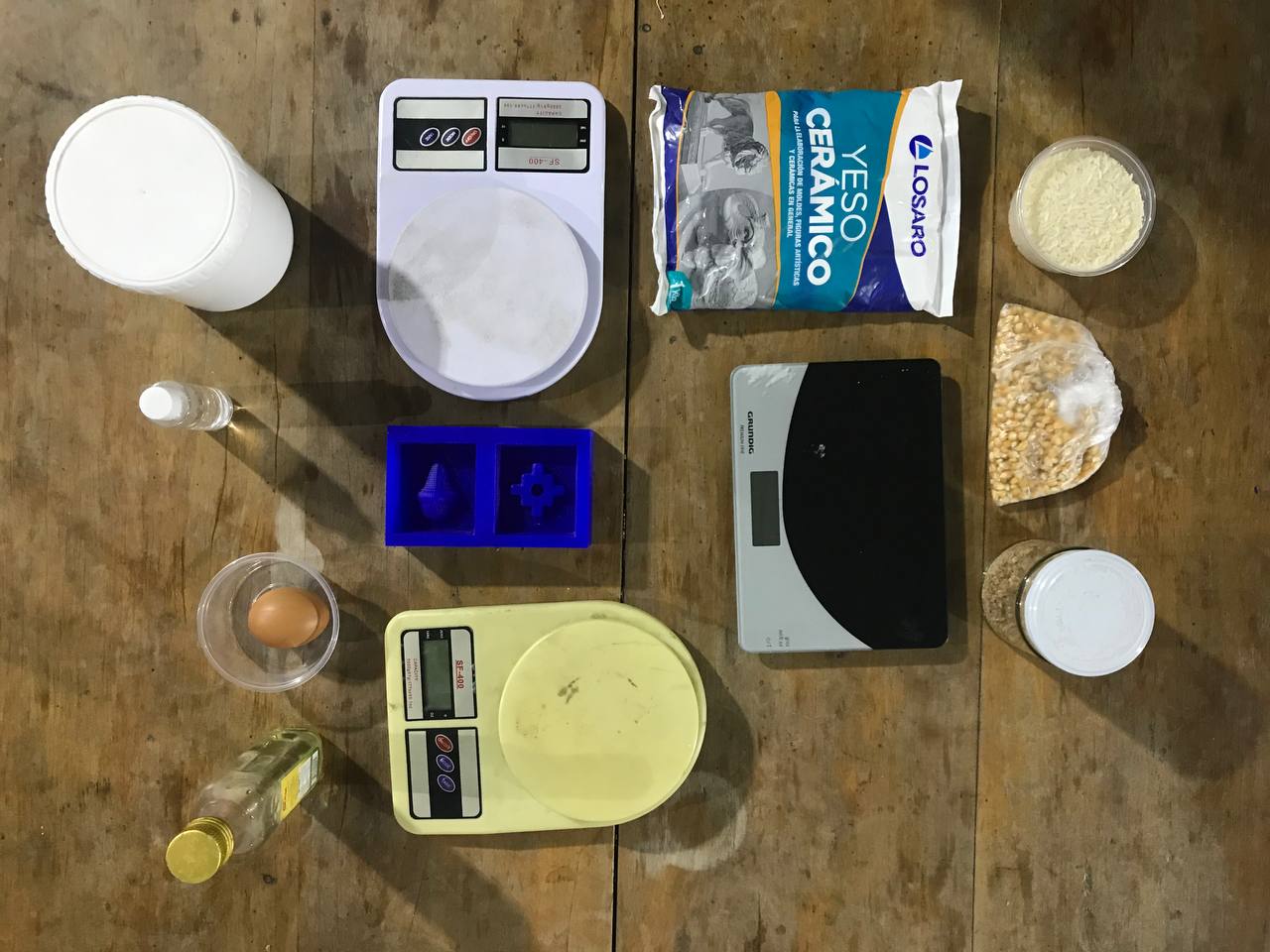
Materials
Silicone Process
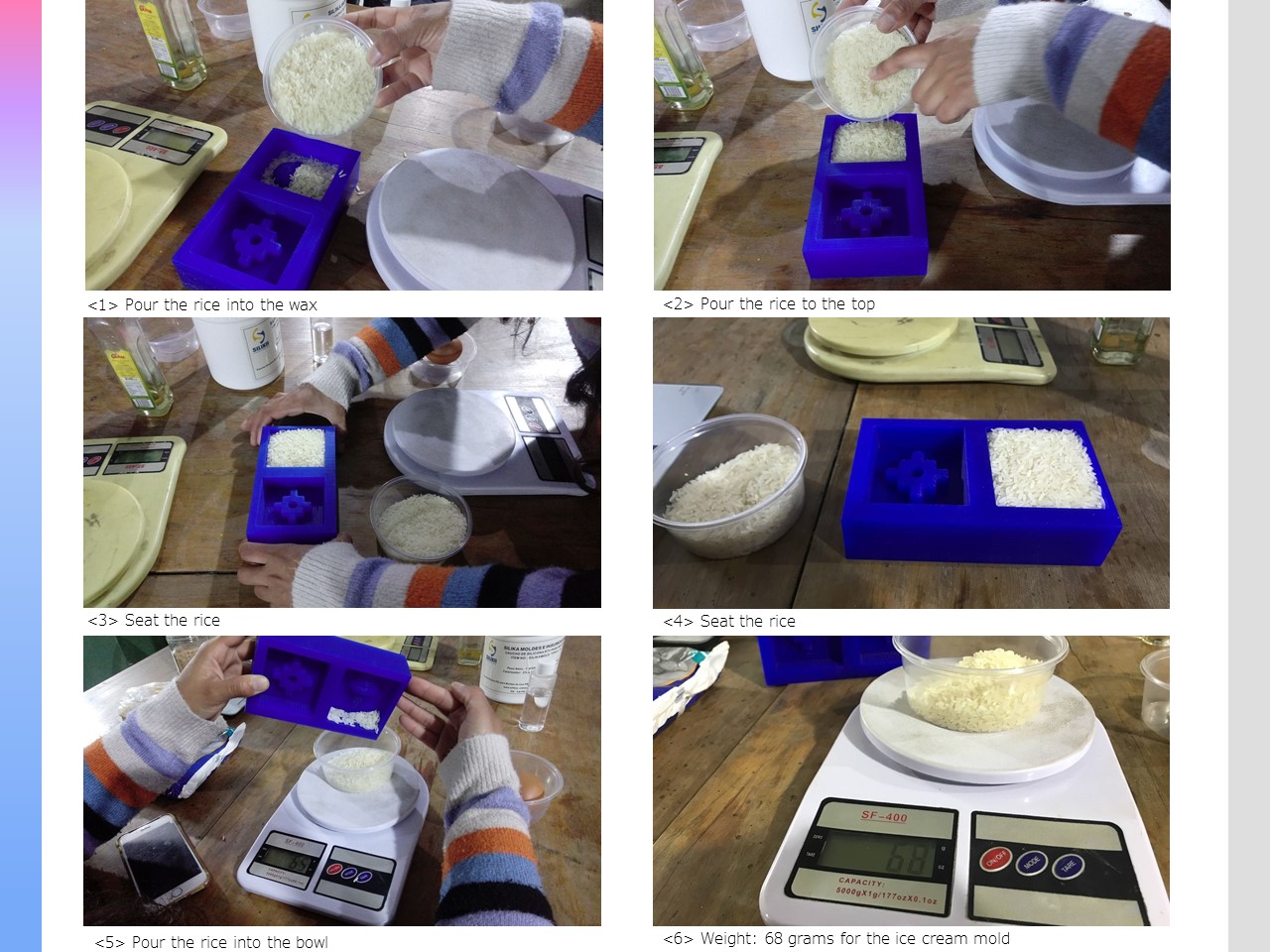
Measurement with Rice
In the rice test the data were similar to the water test, we obtained the following data:
- Ice Cream Mold: 68 grams
- Chakana Mold: 55 grams
- Total: 123 grams
Measurement with Rice
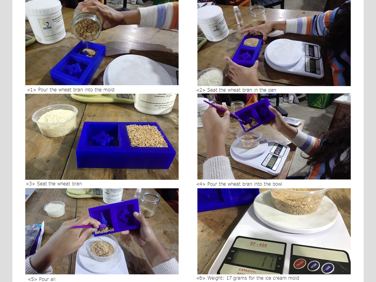
Measurement with Wheat Bran
In the Wheat Bran test, the data was very intriguing, apparently the wheat has more volume than its real weight, the measurements were much lower than the other two tests, we obtained the following data:
- Ice Cream Mold: 17 grams
- Chakana Mold: 12 grams
- Total: 29 grams
Measurement with Wheat Bran
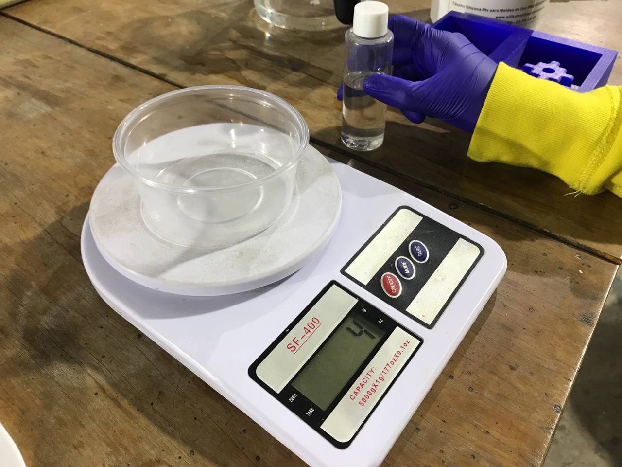
Measurement with Water
In the test with Water, we did the measurement separately and also of everything together. The result is closer to the measurement with rice, but even more accurate. We obtained the following data:
- Ice Cream Mold: 70 grams
- Chakana Mold: 58 grams
- Total: 128 grams
- Complete mold: 130 grams
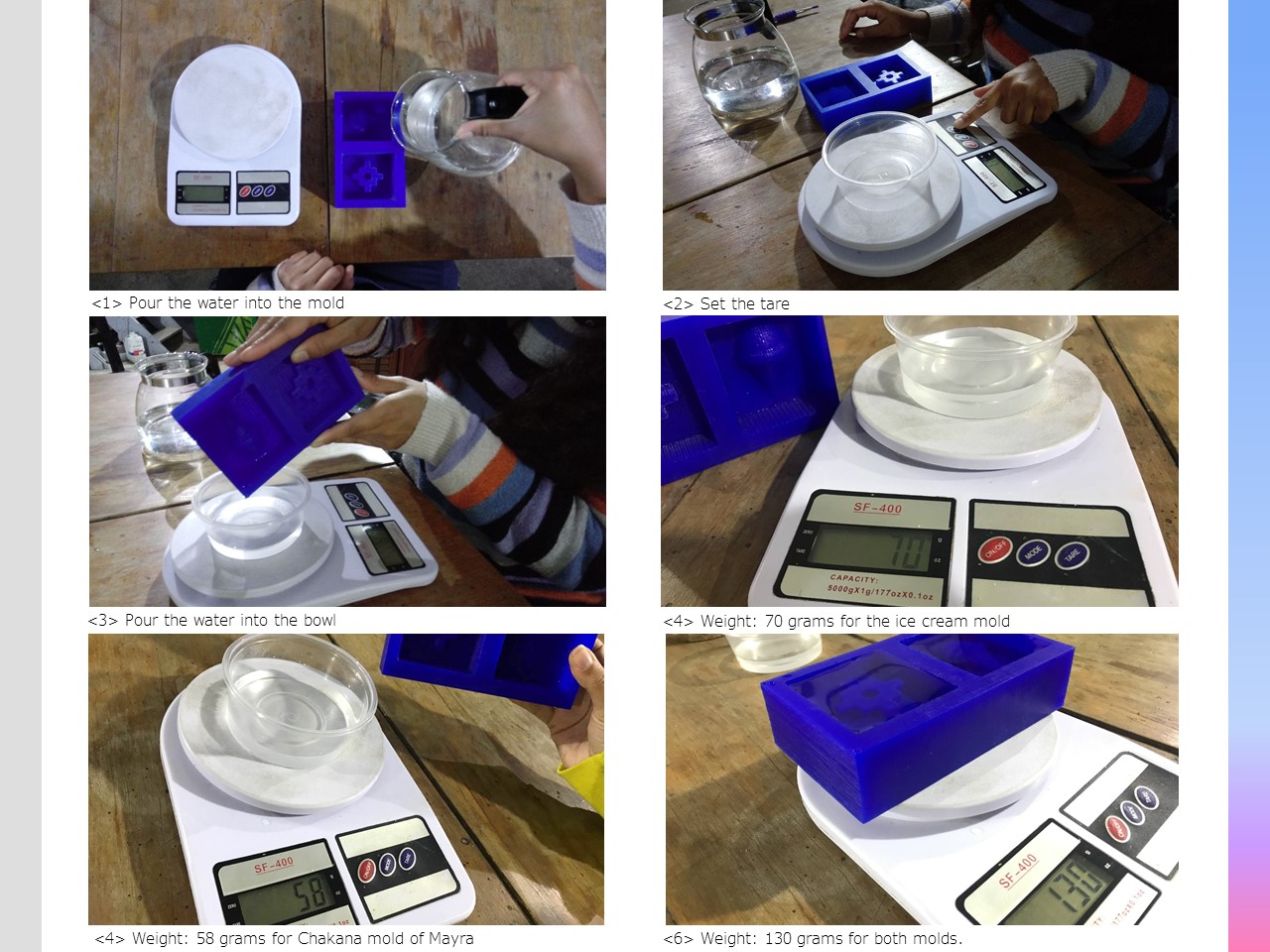
Measurement with Water
Castingwith Silicone
After the measurements we decided to prepare 150 grams of silicone, to ensure that the wax block was completely filled.
The mixing ratio with the catalyst is 2% to 3%; for example, if you need 100 grams of silicone, you will have to mix 2 grams of catalyst. We decided to mix our catalyst by 2.5%.
150 grams of silicone X 0.025 (2.5%) = 3.75gr.
- 2% slow curing process
- 2.5% intermediate curing process
- 3% fast curing process
Catalyst
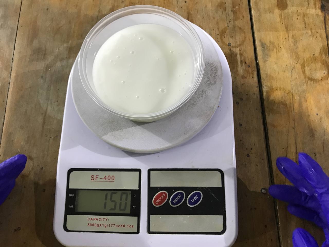
150 grams of Silicone
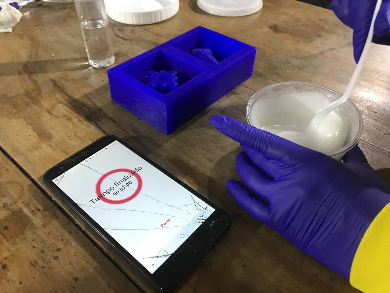
Rossmery, a sculptor friend, advised us to mix the two components in a continuous, uniform and circular way for 7 minutes, being very careful not to remove the spoon with which we mixed. This helped us a lot to reduce the amount of bubbles, which eventually came to the surface, and were not in the reproducible part of the design. Once we pour the silicone into our wax mold, we wait for the time for the silicone to cure and we can unmold.
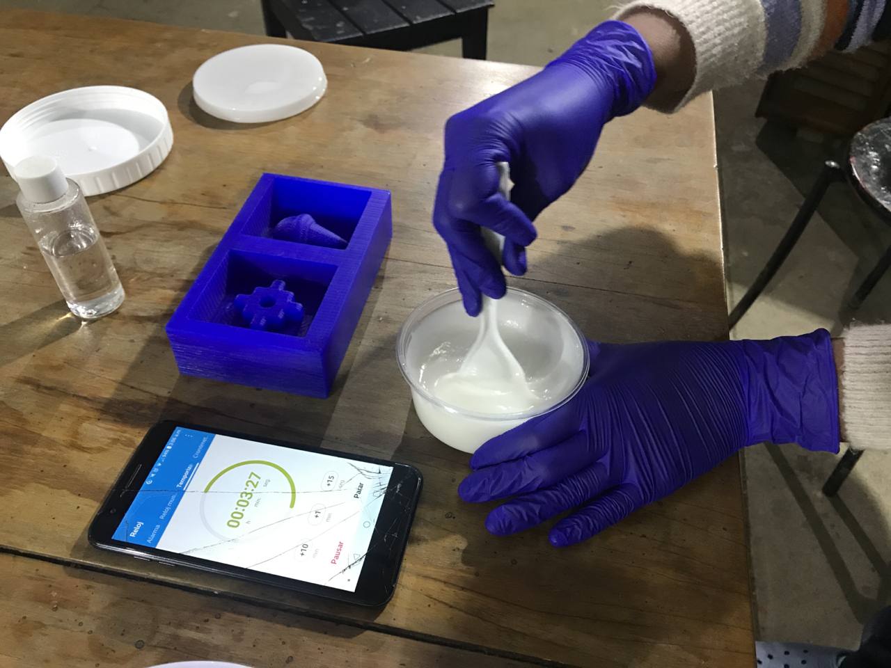
Mixing
Mixing
The curing system works by condensation. When you mix and pour the catalyst into the silicone; alcohols begin to form and the silicone loses moisture; for this reason, there is a slight contraction from 0.01% to 0.02%. If you let the mold rest for 24 hours, while it's in the contraction process, you ensure the faithful reproduction of all the details of your mold, otherwise, if you remove it after 4 hours, you could lose quality if you make molds of sculptures or complex miniatures.
24 hours later we proceeded to unmold. Let's see what happened!⏰
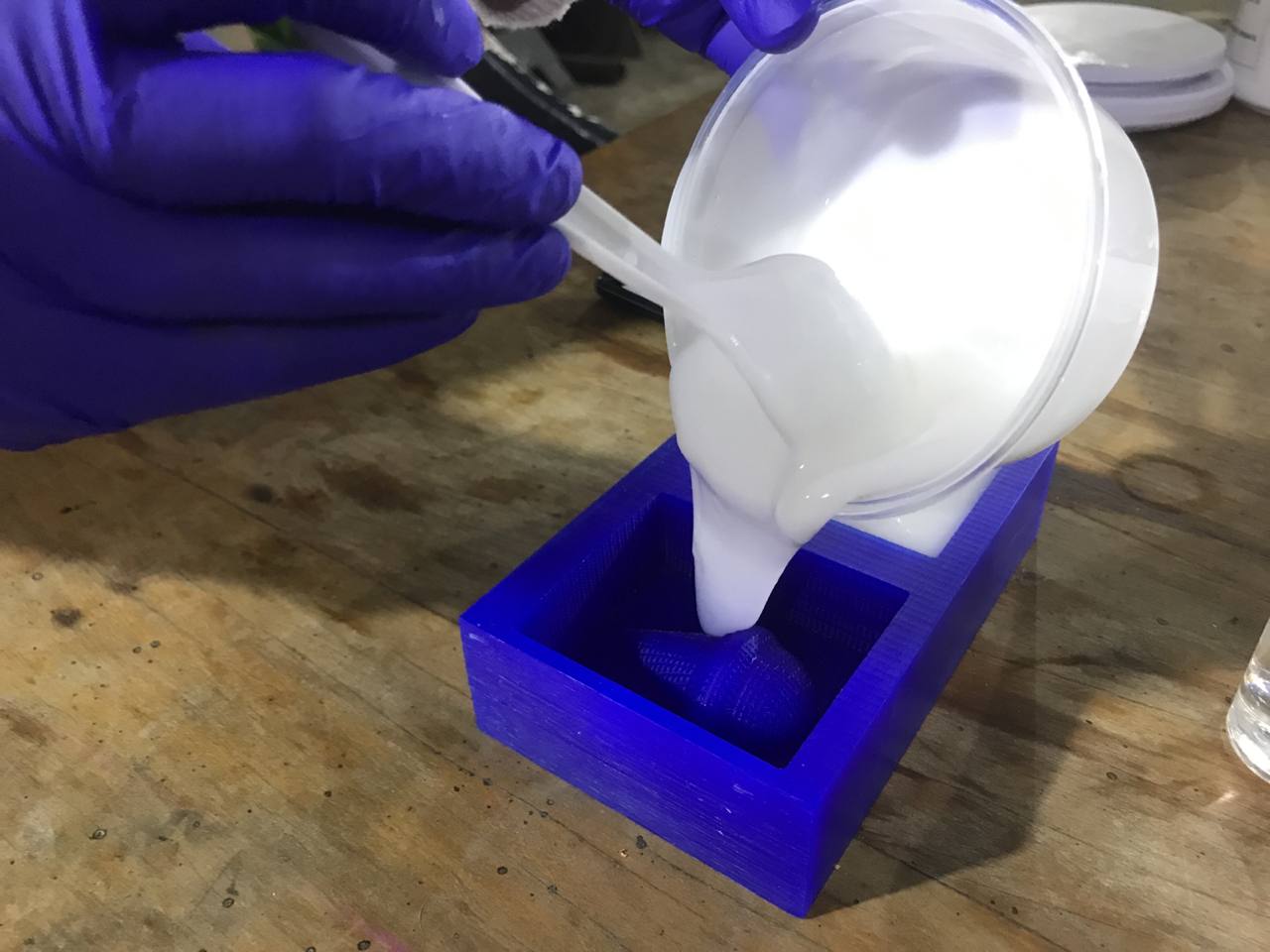
Pouring the silicone
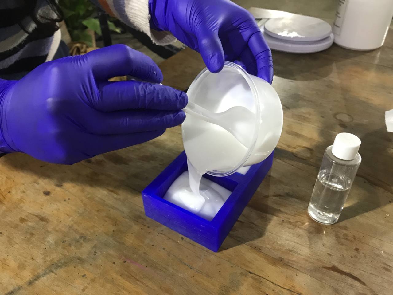
Pouring the silicone
Pouring the silicone
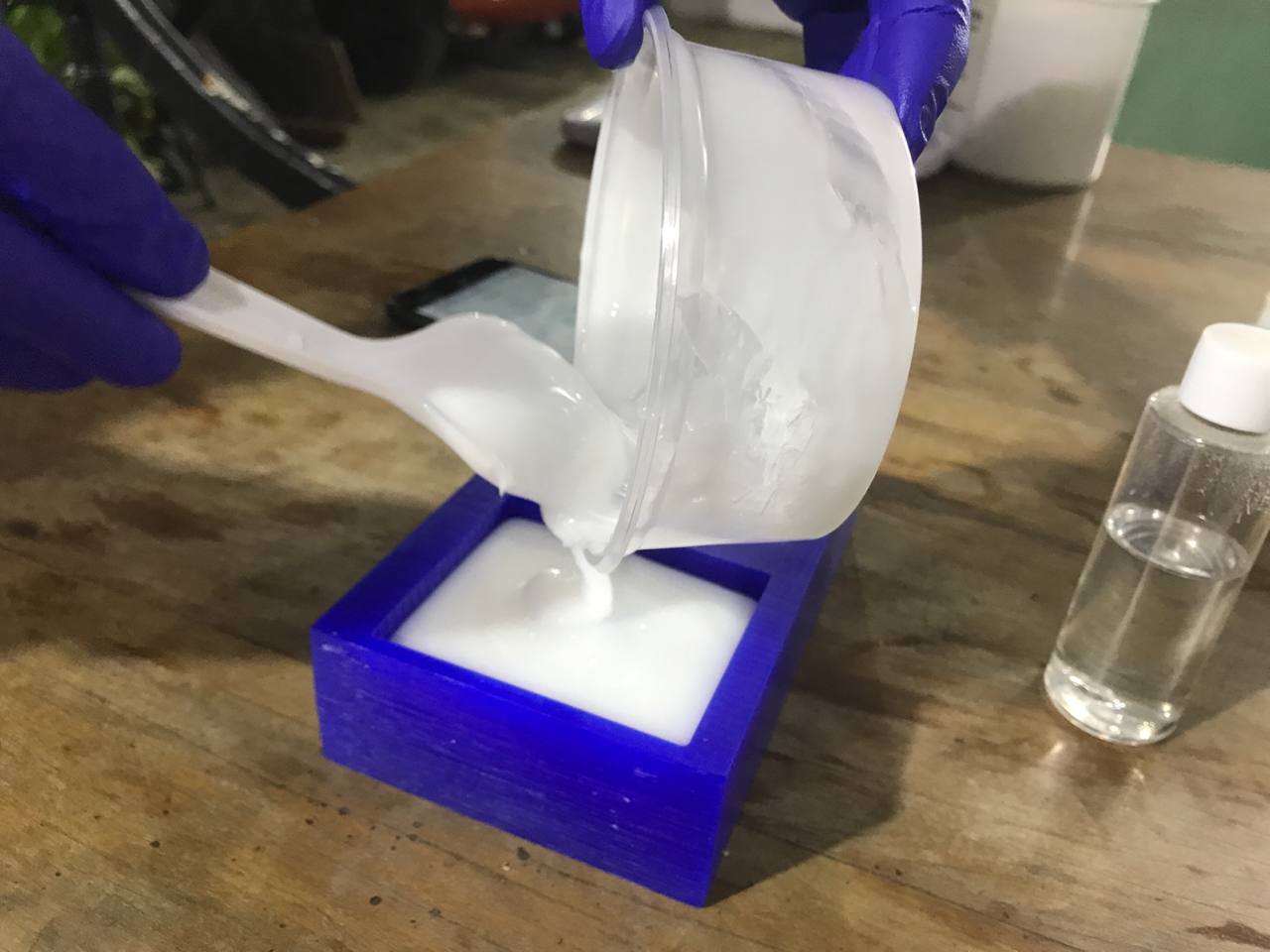
Seated silicone
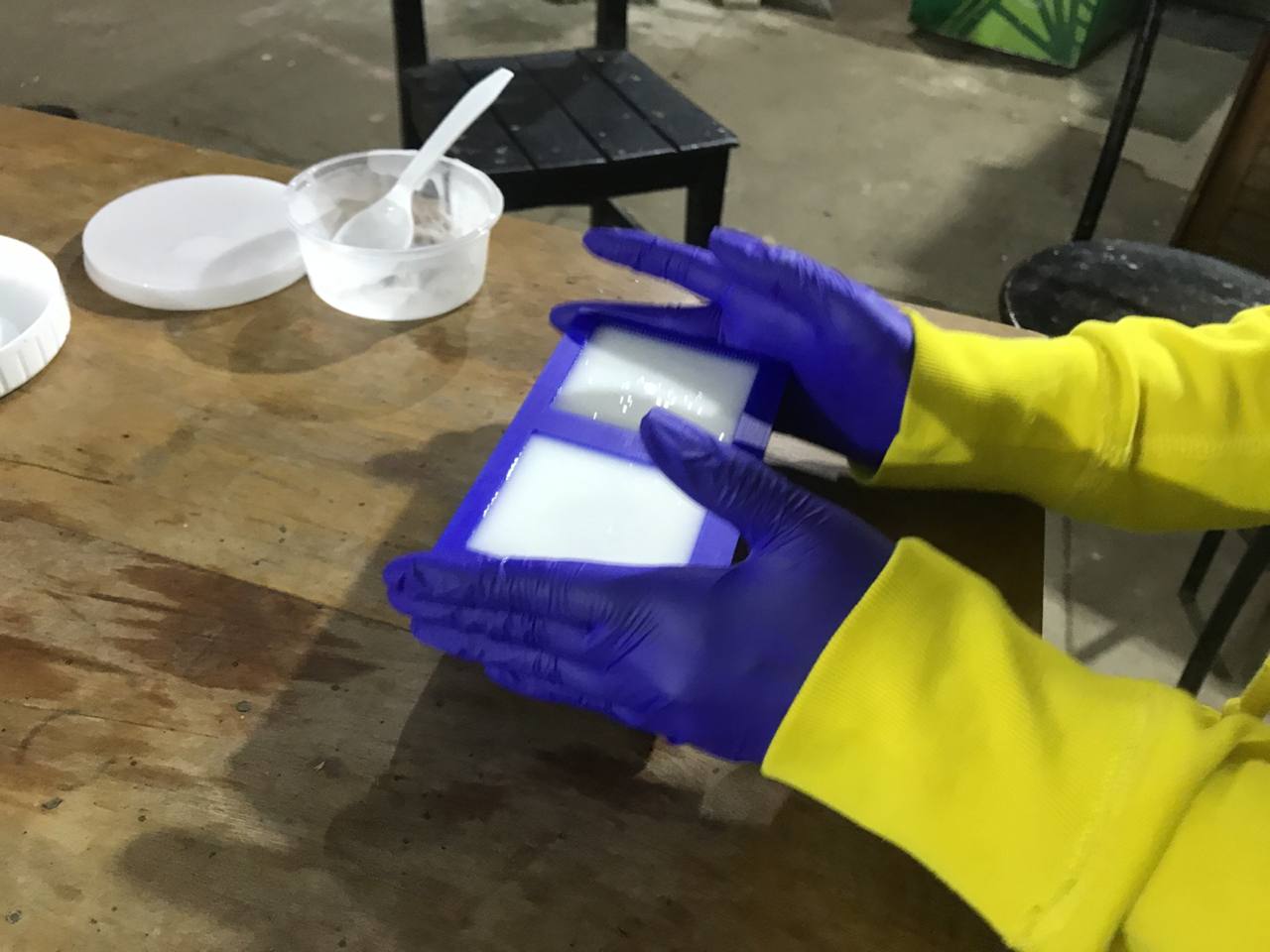
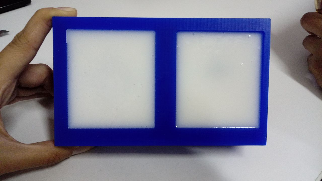
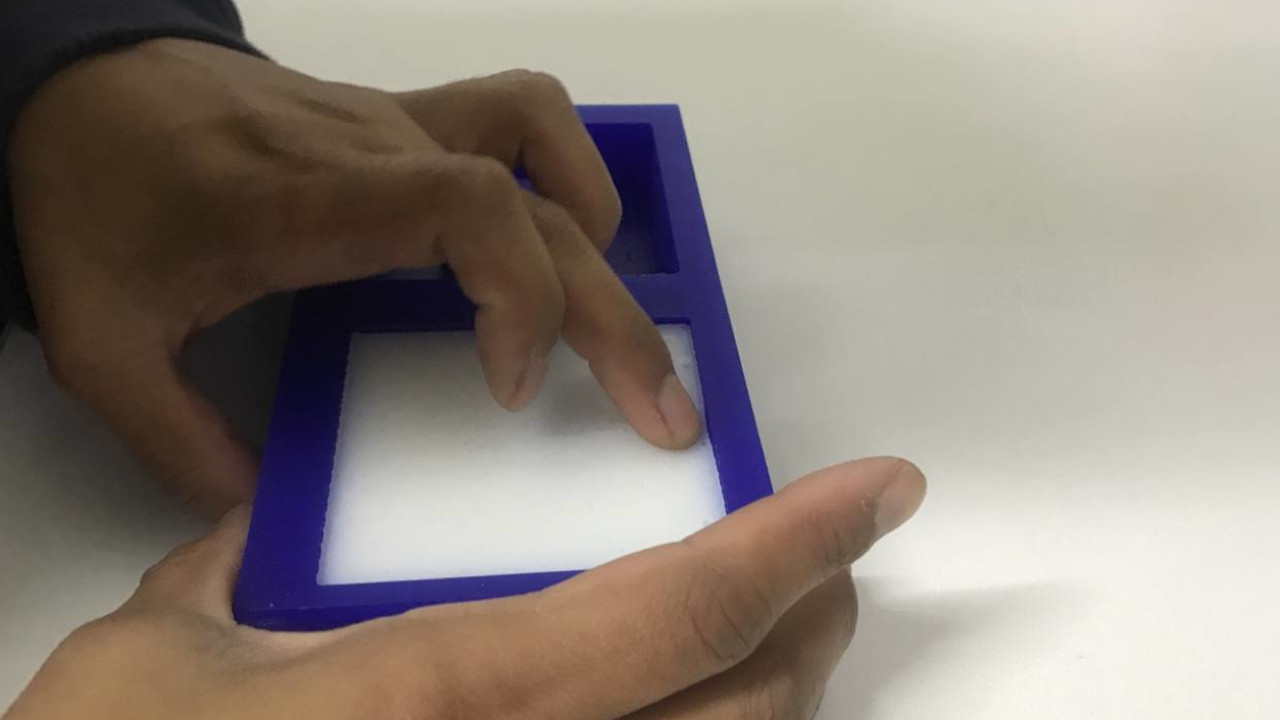
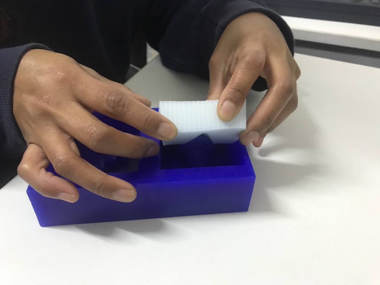
Unmoldingthe Silicone
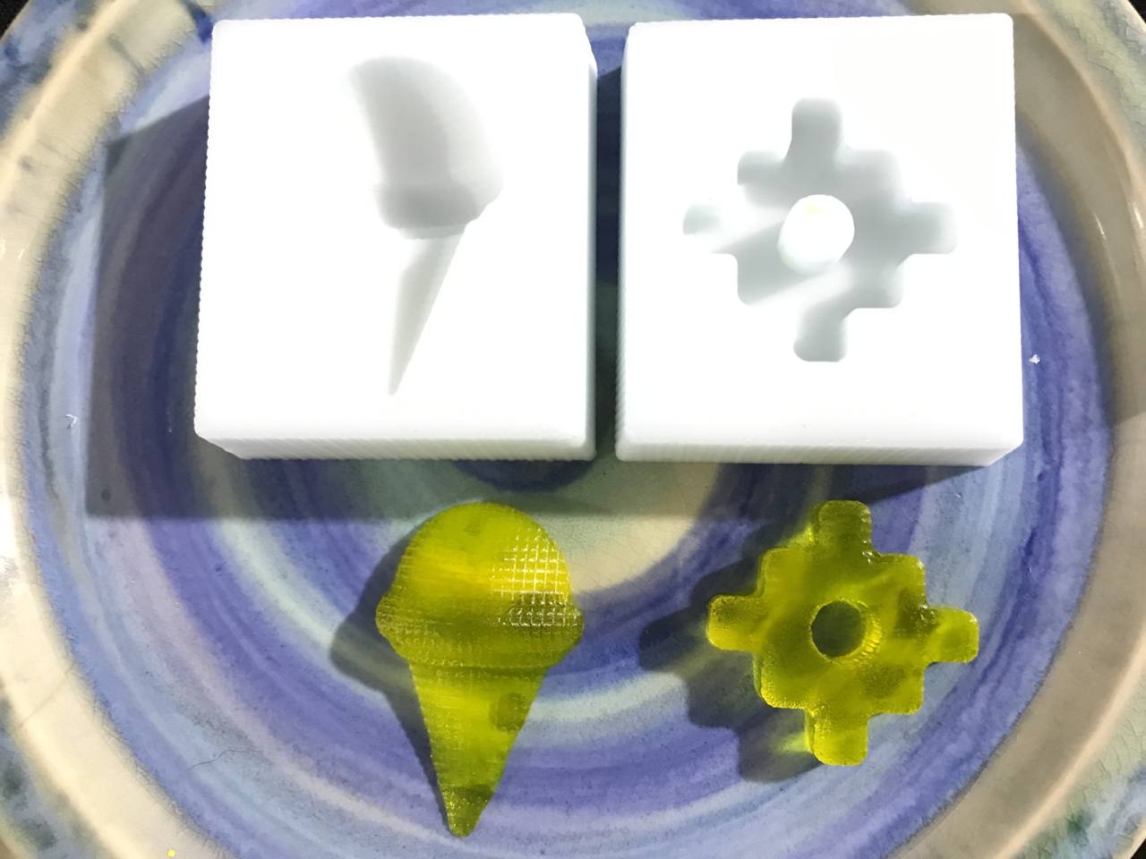
When the time comes, we check with our hands that the silicone has hardened and we proceed to unmold. The sloping walls were very helpful, it takes a little force to unmold. The result was good, the few bubbles remained on the outside. The reproduction was faithful to detail.
Silicone ready
Unmold Silicone
Unmold Silicone
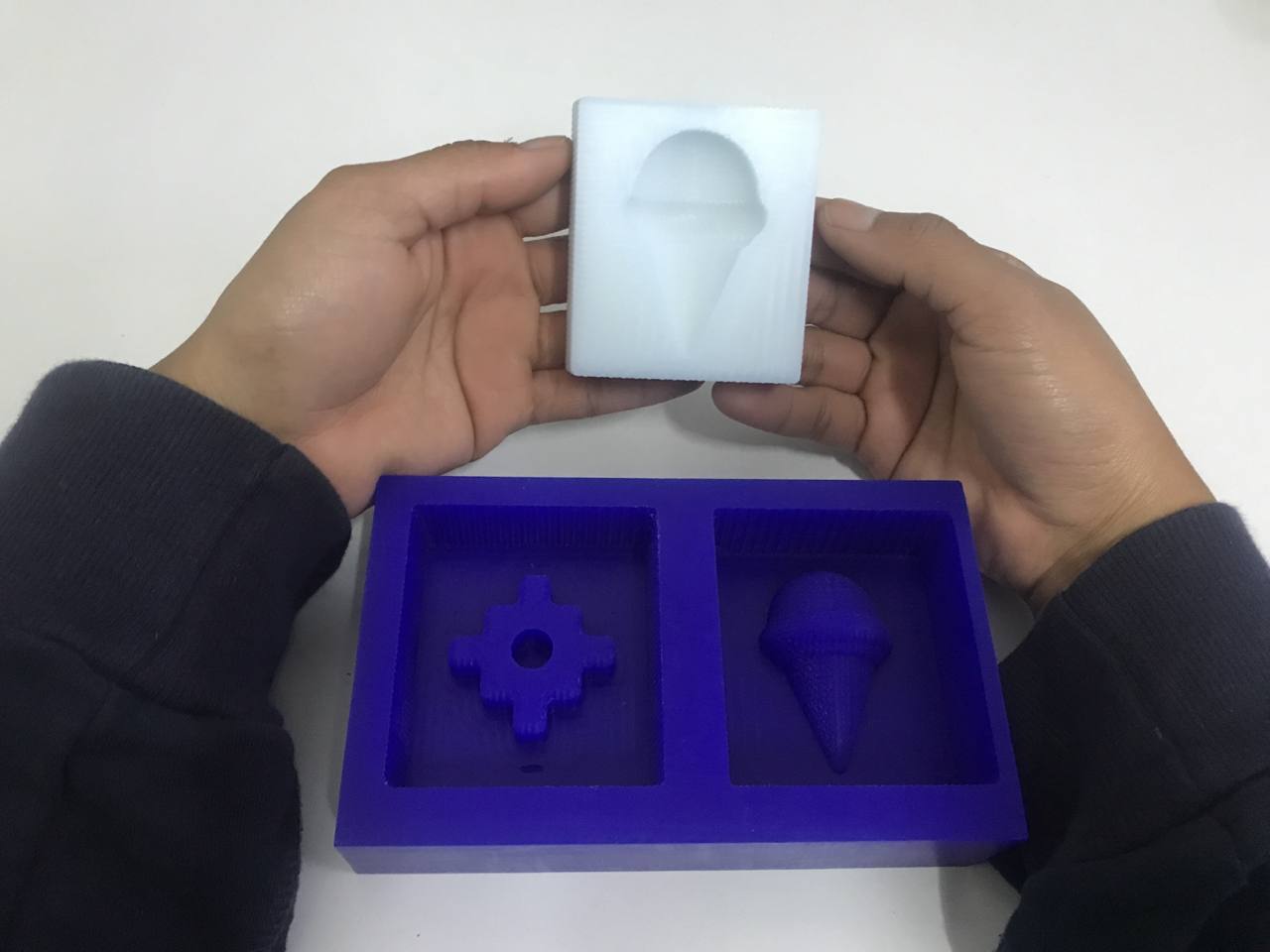
Unmold Silicone
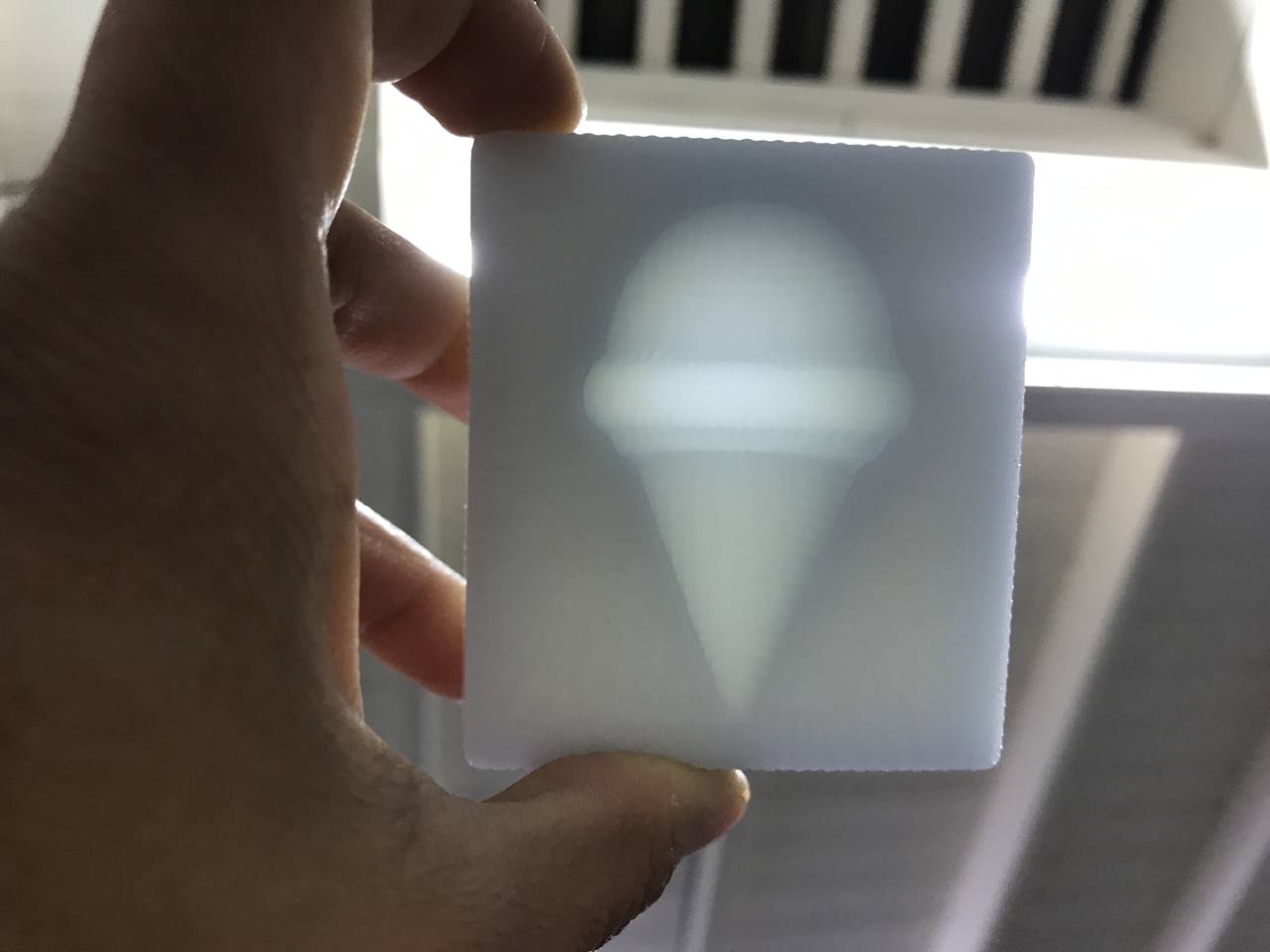
My Ice Cream Mold
JellyIce cream
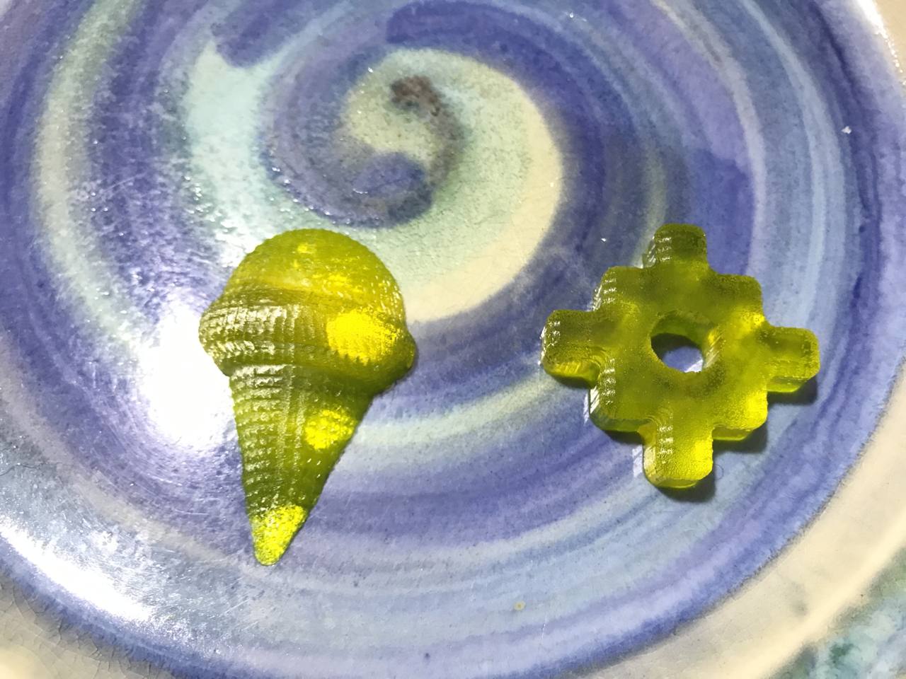
This is the most anticipated step of all: reproduce the first object. Together with "GMH 000", we tried to make ice with our molds, but it failed. As a second option, we use pineapple jelly 🍍 and pour it into our silicone molds. as you can see, the result is satisfactory.
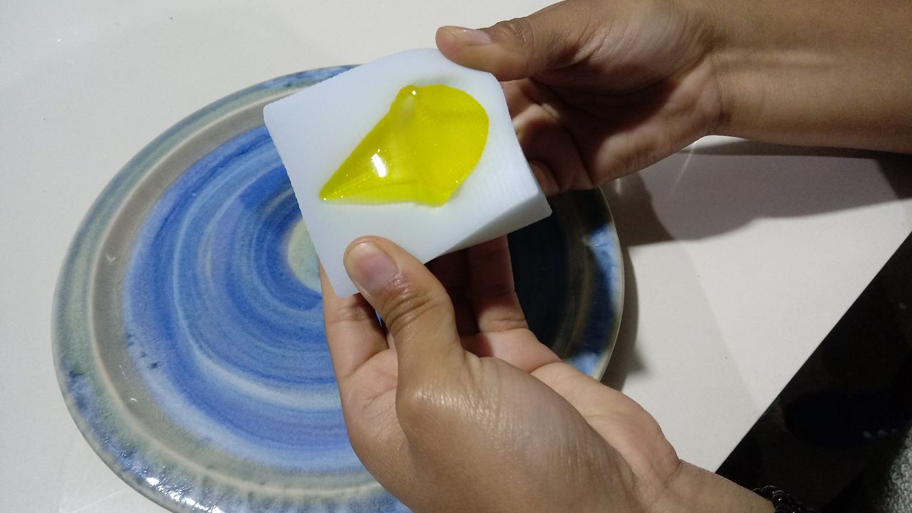
Jelly Ready
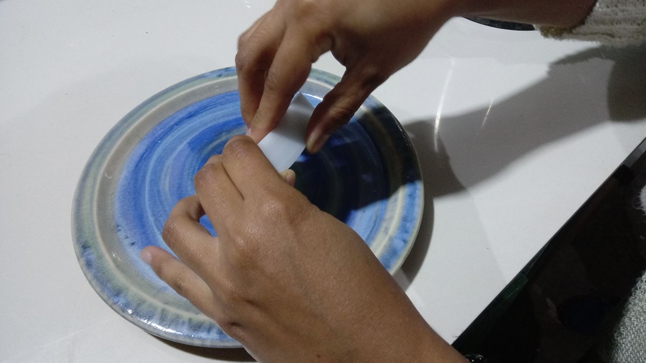
Unmold Jelly
Unmold Jelly
Jellies
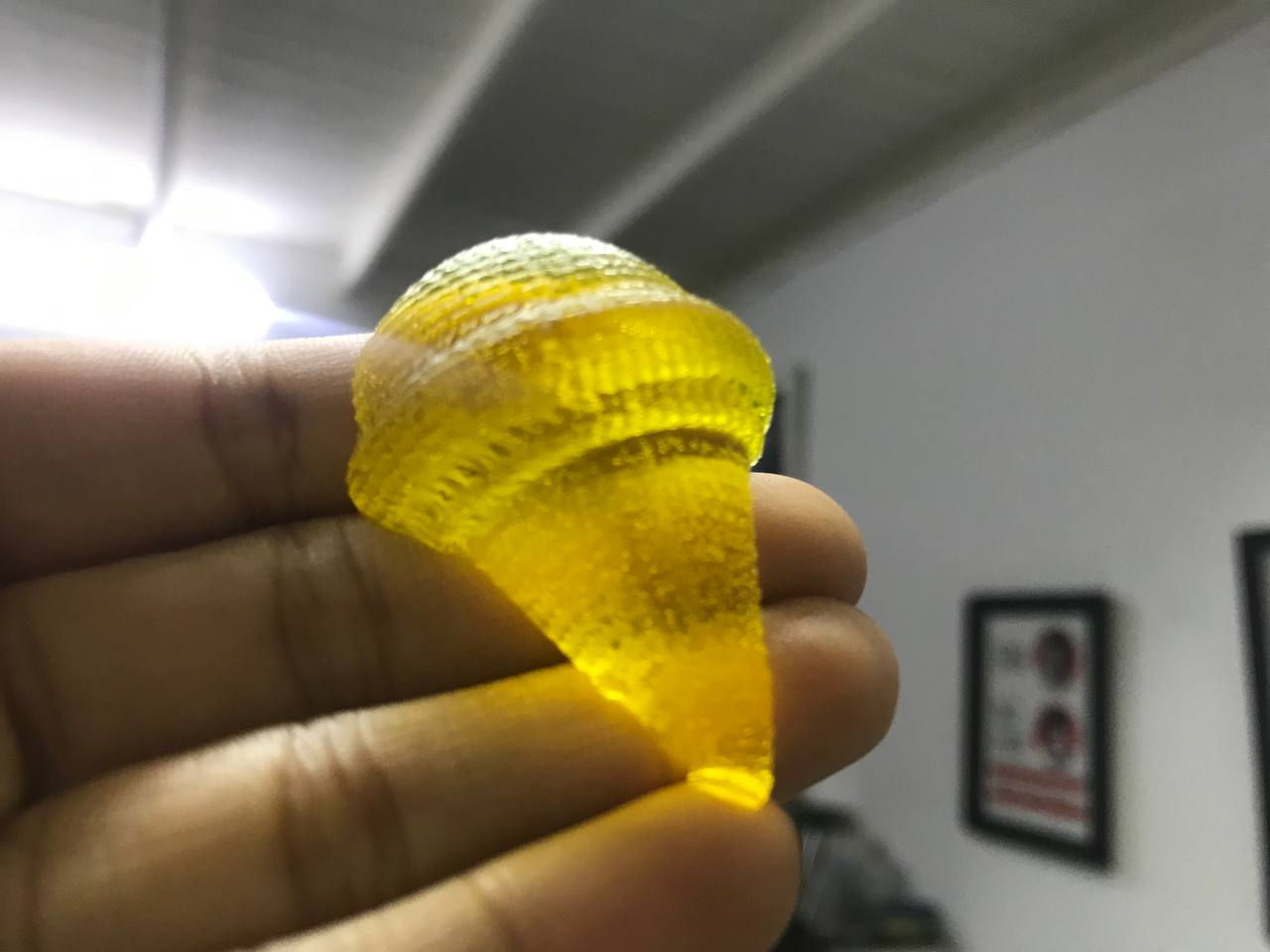
Ice Cream Jelly
AboutLearning
-You must correctly measure the work area in x, y, z of the milling machine that you own; because any 3d machining work you do will depend on it, remember that wax is manipulable and that you could build your own custom block according to the measurements you need.
-It's important to have more than one cutter for milling available, so as not to suffer in the expectation of it breaking!
-If possible, next time I would try to buy the materials in a place where the products have available and up-to-date technical data sheets. Unfortunately we did not find a provider with these characteristics this season.
My Verdictfrom what I learned
-Due to lack of materials, I could not develop more than one mold. But I had liked to experience a little more.
-I loved the level of detail that can be obtained with 3d machining. You can design thumbnails and highly accurate things.