Link to Interface and Application Programming Group Page
We start with Andrew showing us what is best to use as he hadn't used a lot so by using something that he knows this will make it a lot easier.
He suggested using either =:
Processing is set up kinda like Arduino so you have a simple app that shows you want you need to place in each section. There is 'void setup' and 'void draw' they are set up the same as in arduino but obviously there is 'void draw' which is explained below.
      Void setup
        - This is the same in arduino it is the parts of the sketch you just want to be there so it knows what you are doing.

      Void Draw
        - Redraws the screen for you as it is moving along
        - Its refreshing the screen over and over but you can't see it was it is going very fast. You can slow
        this down if you need to by changing the amount of times it is moving.
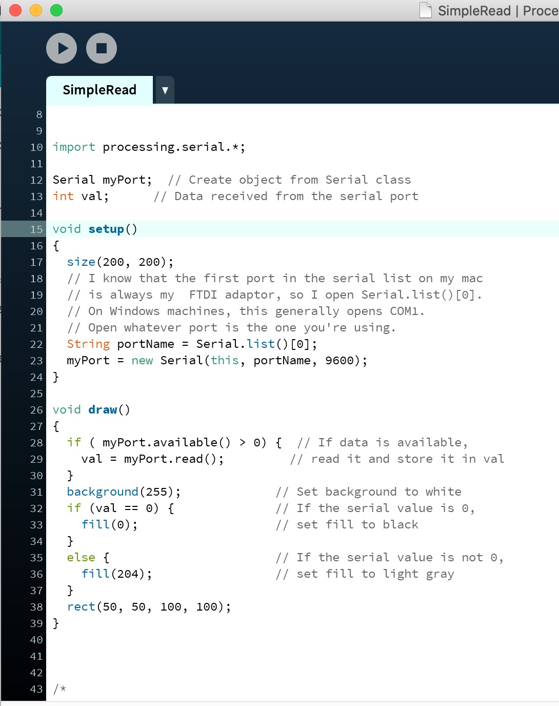
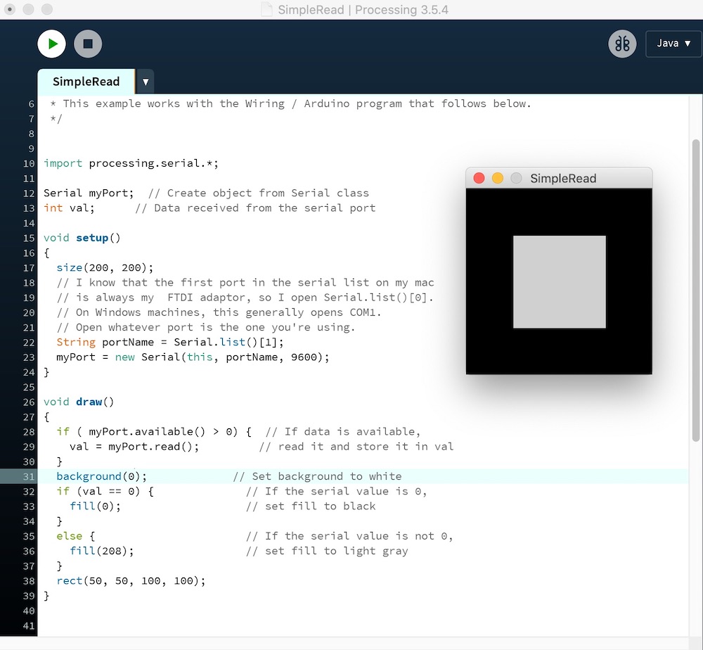
You start by reading the sketch that has been given to you as an example, follow the instructions as show below to copy the sketch into arduino and compile it onto your arduino board.
It wasn't working for me so then Jonny came over and showed me that because of the sketch I needed change the port on the sketch from 0 to 1 as this is the correct placement for my port.
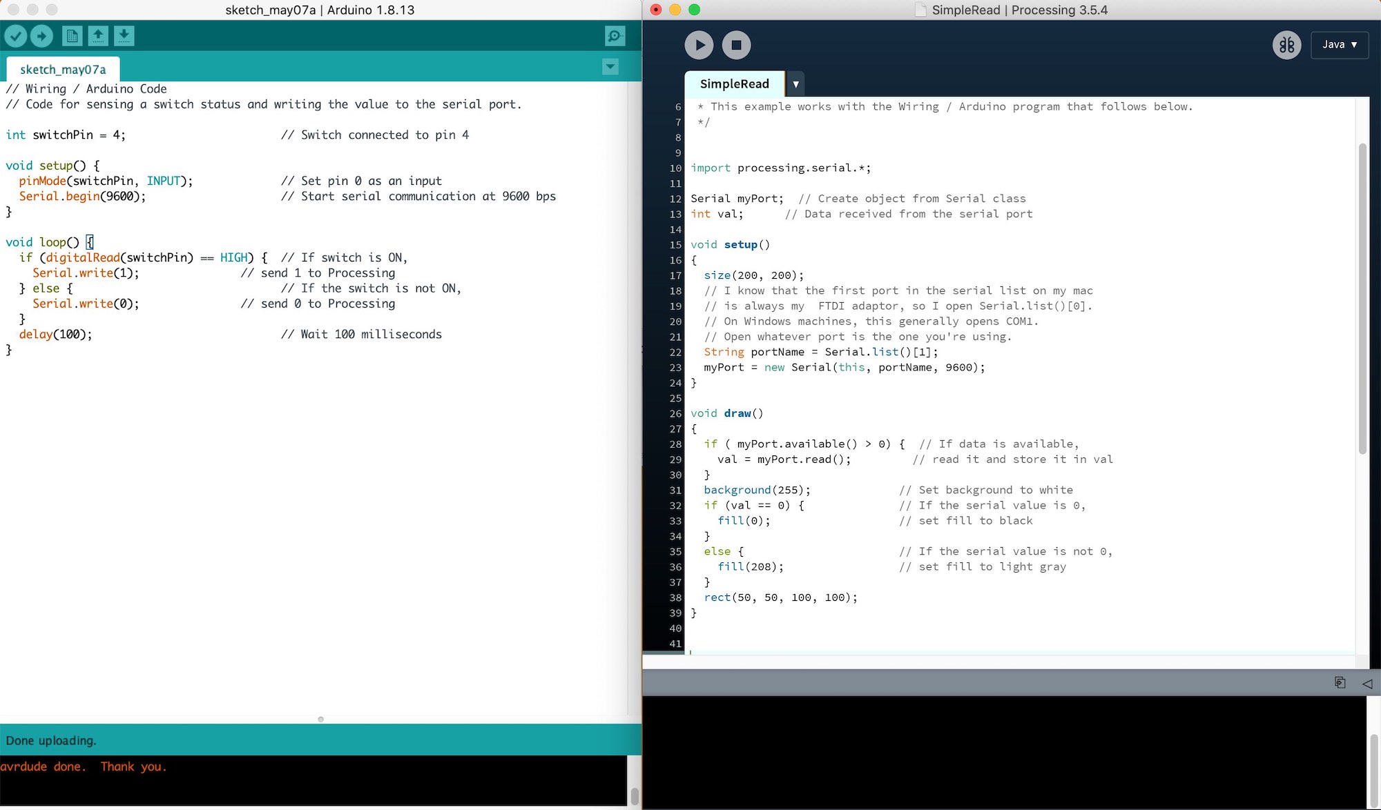
It then worked which was great as this meant I could move onto another sketch to get the light working.
I also changed the background colour so that I could understand more what I was dong when I was reading the sketch.
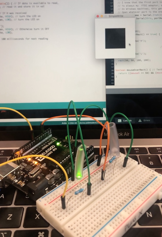
Adding a LED and using the example 'serialWrite' to get the LED to light up as this will be more helpful in the long run with my project.
I then moved on and made two LED's light up using the same coding to see if this would work which it did!!
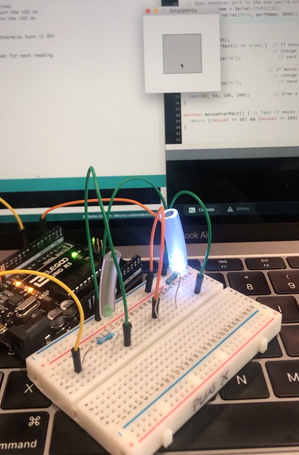
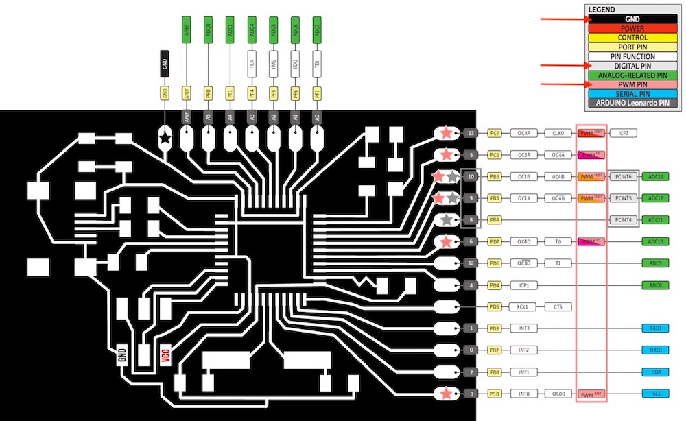
I then needed to do the same but with my board, so I figured out the pinouts that I would need to connect the LED's to the board. I attached everything together with the arduino first to see how this would work with the arduino.
I then plugged in my board to the Atmel-ICE to place the programme onto the board and then I upload it...
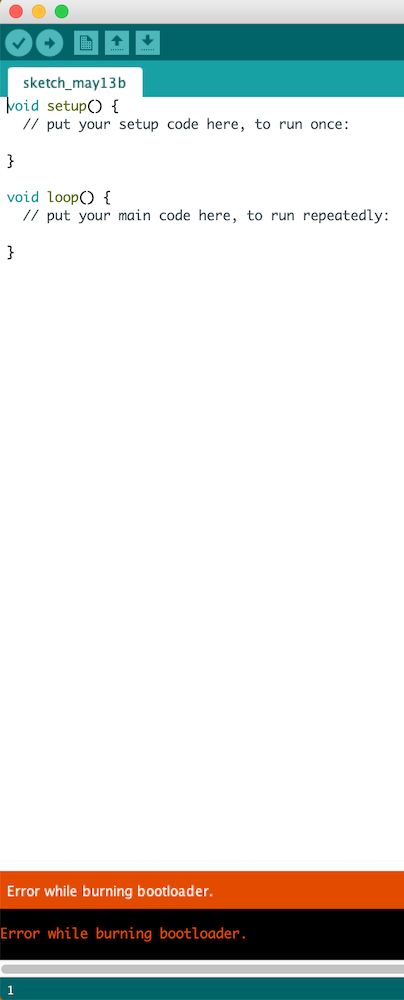
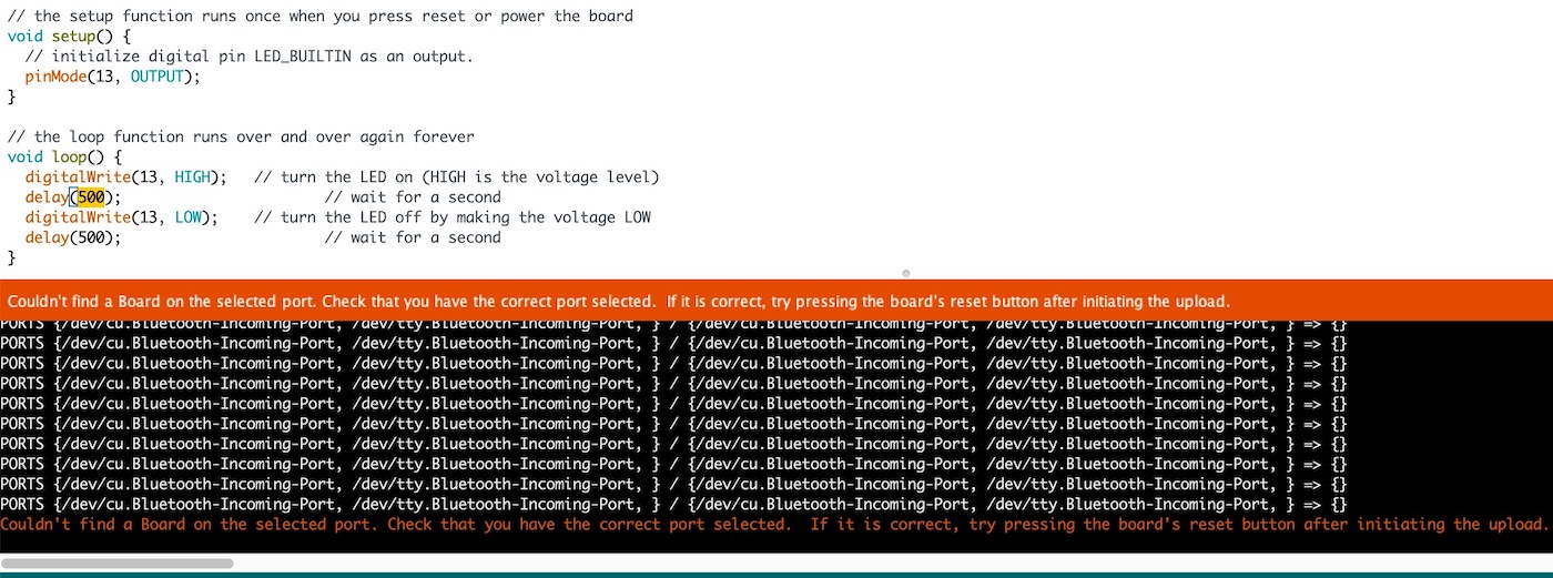
This didn't work and I kept getting the error message saying that it couldn't do it because it couldn't find the port.
  Couldn't find a Board on the selected port.
  Check that you have the correct port selected.
  If it is correct, try pressing the board's reset button after initiating the upload.
I am a little confused by this as the last time I used this board it said I didn't need to tell it a port as this should just work.
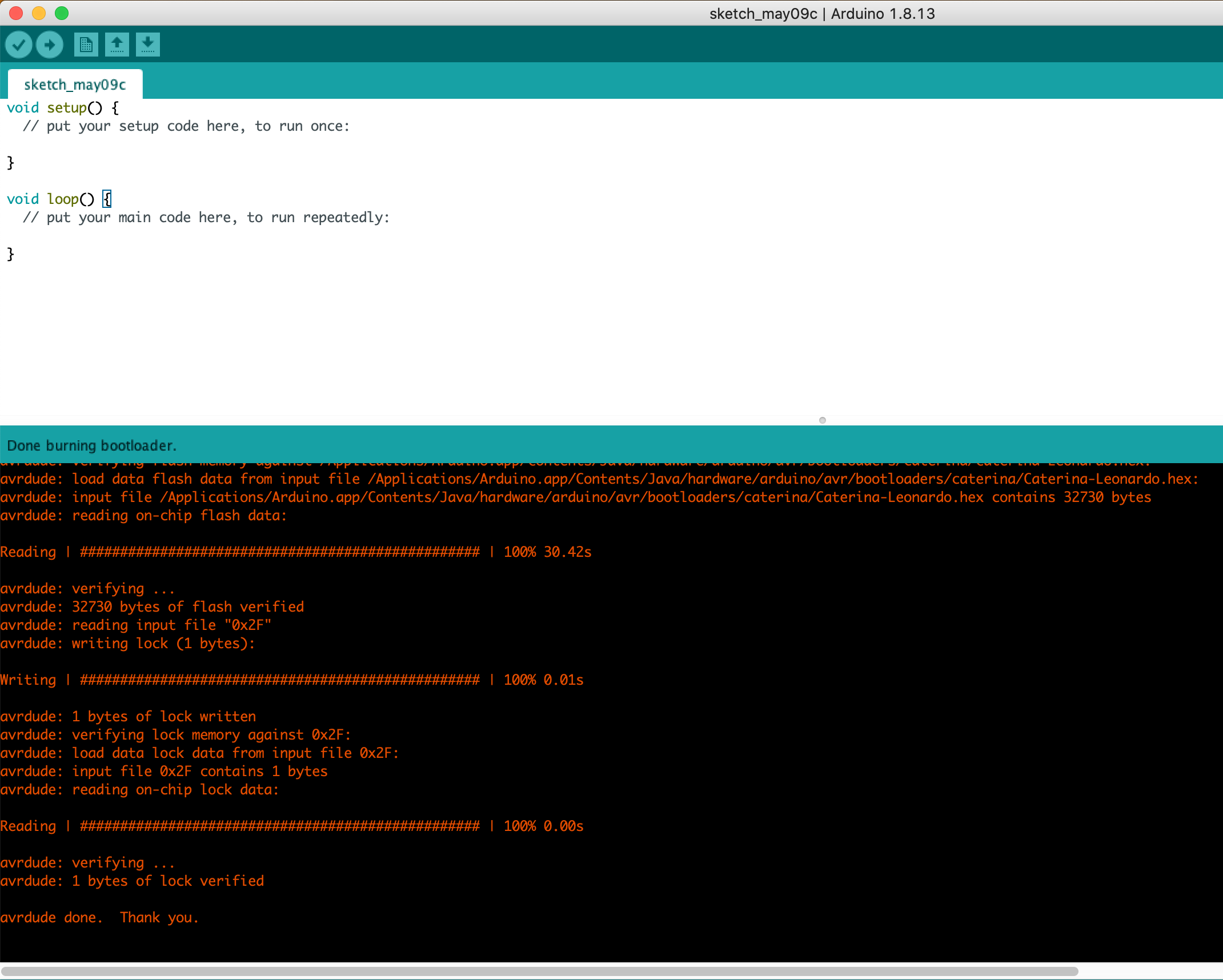
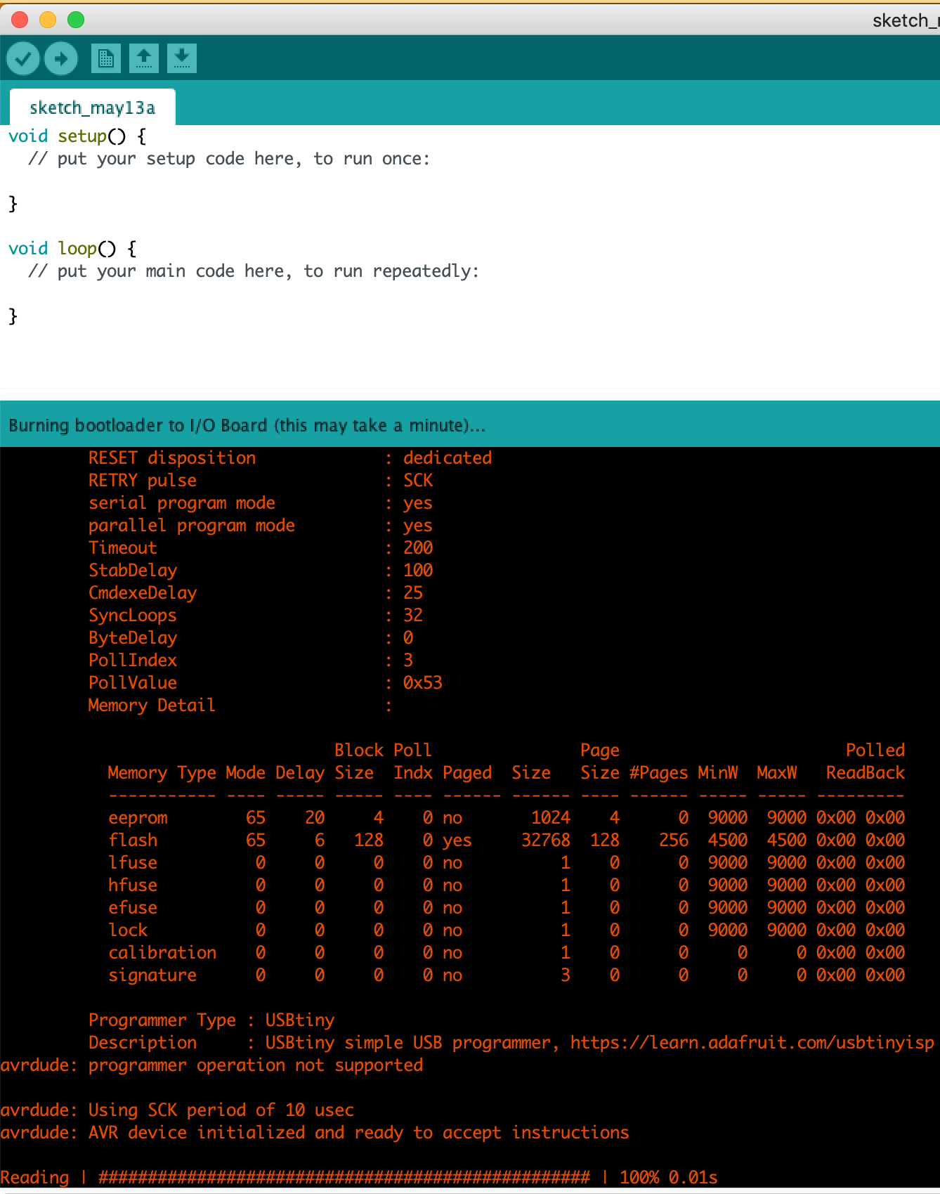
This ended up being a very long processes and I have no idea how last week I managed to get anything onto this board. Andrew ended up having a look at it and I realised I never uploaded the bootloader, so I tried to do this.
Turns out I hadn't burnt the bootloader so I did that which worked fine.
I then kept trying to upload the file to the board, I think I must have tried is 20 different ways as we have many different cable I can try and different ports. Restarted Arduino, used my original programmer rather than the Atmel-ICE this didn't work, we then tried our windows laptop as this can be more forgiving on the ports. This was the things that wasn't working as I could burn the bootloader just not get the port up for the arduino to upload something to it.
Then Andrew came in and gave it a go to see if I was just doing something wrong, he went through my whole board checking all of the components, the traces and my soldering.
He noticed that one of my soldering pins on the USB was connected which would make a lot of sense so I went back and tried to get it to flow better as this was the issue. I then by mistake managed to get them to solder together so there was a sort circuit, so I got a scalpel and cut away the solder attaching them.
Andrew then realised that by me doing that I had moved some solder from another pin that now wasn't soldered. After all of this Andrew just gave it a go himself and then we looked under the USB microscope and this is what the USB component looked like...
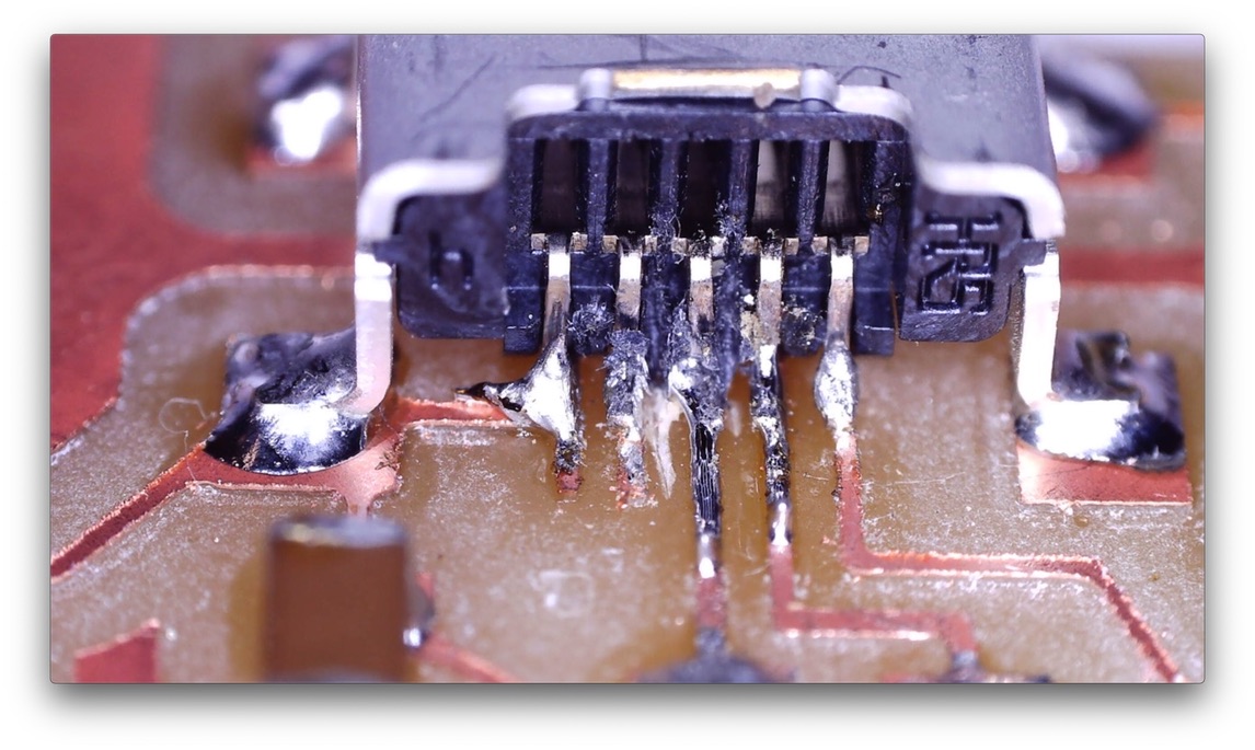
Andrew has suggested that I just make the board again as I am going to need a working board in the future and we know that this chip works for me.
So now I am going to remake the board and hopefully get it all to work!! My fingers are crossed
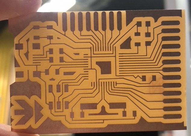
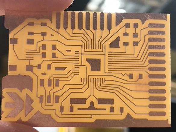
Cut on MDX-540
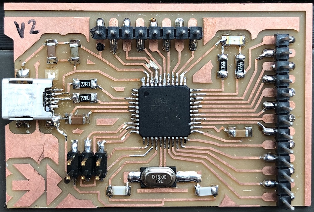
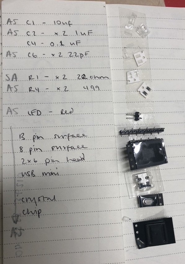
Change capacitor as put a 0.01uF rather than a 0.1uF
Andrew then started testing out each area of my board, seeing if:
: he noticed that there was no voltage from under the USB port to the VCC on the chip (pin2).
I removed the other two capacitors as Andrew thought to just check that they were not getting in the way of the readings we were getting.
This was very odd as the two pinouts on the USB were getting it, the use was that because of the USB going under there could be a short under it without us knowing.
I then had 1 of two choices, as the USB seemed to be the issue the best option was the remove it to see what what happening and if it is defiantly something to do with that rather than playing around and not knowing or I could just scrap the board and start again. I didn't want to do that yet as I felt I wasn't going to do anything to the board it would be pointless as we have no idea what the issue is other than the USB is making the voltage going down under it.
I removed the USB, checked the voltage and it was working fine so I 100% knew it was the USB doing this and not another part of my board.
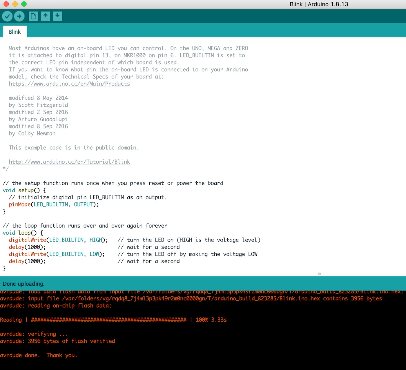
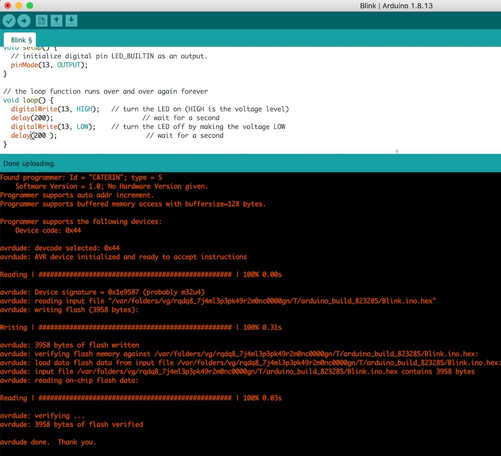
So the boot loader worked, I then tried to load a blink sketch which also worked!! Woohoo
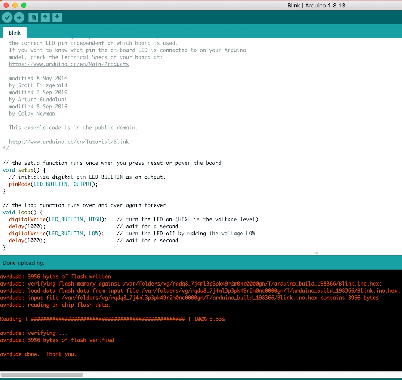
I then tired it with the LED turning on by changing the sketch to pin '13' rather than 'LED_BUILTIN' which should then turn the LED on my board on to a blink motion.
So previously when we were looking at the board I had put the LED in the wrong way around, so I just flipped that over.
Now that I had changed the USB port for some reason the LED was not working, I managed to burn the boot loader, upload a programme but the LED would not blink with this programme in it. This is when I realised the LED was not working, I took it off to replace it and that one didn't work either which was very odd. I then thought I would try to see if the LED was working after I had taken it off the board just in case the resistors were wrong so the circuit was blowing it. But they worked fine after I had removed them and they didn't work on the board.
At this point I was going mad and as there was nothing much else we could think of to do I called it off and decided to make another board!!
So as Andrew suggested I cut off all the copper that was under the USB port to make sure that none of the previous issue would come about.
Cut on MDX-540
Resistors where wrong so I replaced them, tried to burn the boot loader but this did not work, it was late in the evening so I decided to go home after that fail. I just couldn't have another board that failed in one day!!
Cut MDX-540
I checked the board again, made sure the components were correct, compared it to my other boards, check my soldering parts and everything seemed well.
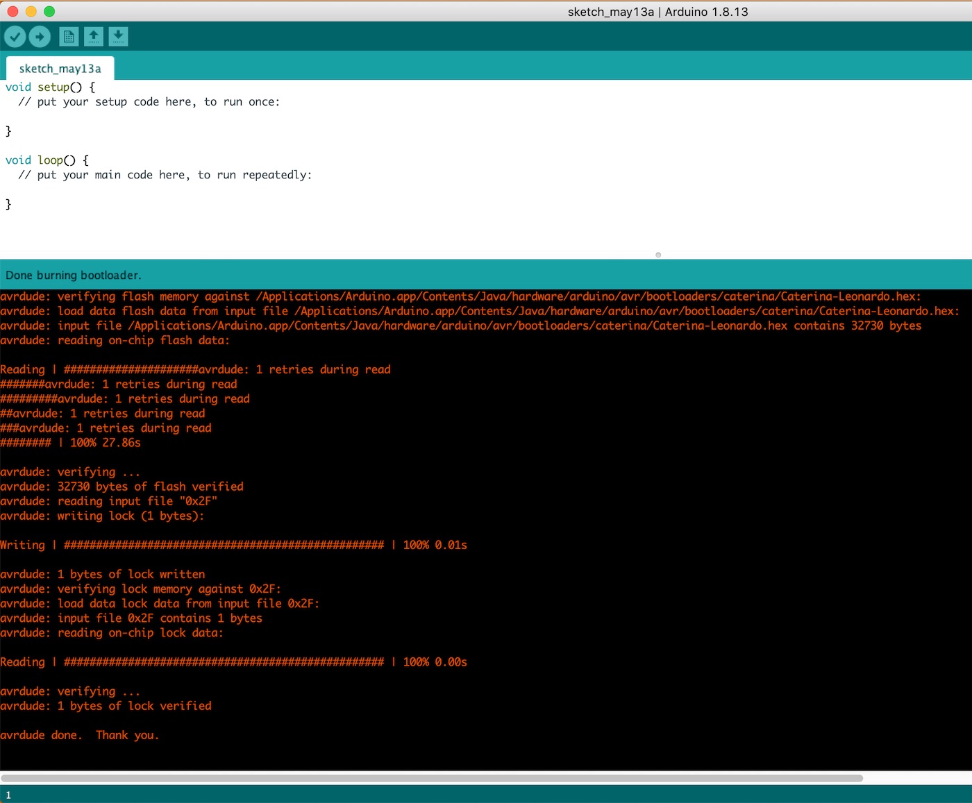
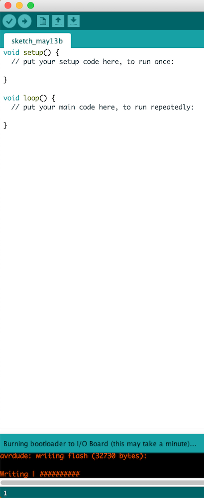
I then plugged it in press 'upload bootloader' and there it was 'writing#####'' I was so so happy!! Did a happy dance around the workshop and then proceeded to upload a blink sketch - this worked too!!
But this weird thing kept happing were it would be in the port and then when I uploaded the sketch it would then disappear like it then didn't recognise it. I kept checking the blink sketch so that the LED would blink (1000) and then (200) and then (1000) to see if this was changing each time and it was.
I also kept getting something like it was trying to connect to the bluetooth port but obviously it was not connected to that port. I showed it to Andrew and he had never seen it before, he then tried it on his computer to see if it was an issue with mine but he got the same.
I then tried out windows computer as these ports are more forgiving and I don't need to have an adaptor between the board and the port. This was also giving the same outcome and I had no idea what to do.
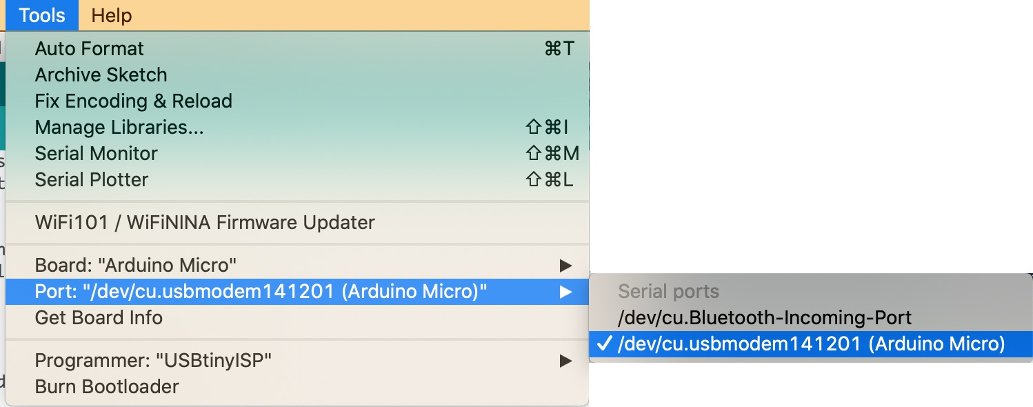
Luckily Andrew had a google and someone else had the same issue when making their own Leonardo board and they instead of choosing the 'arduino Leonardo' you choose the 'arduino micro'.
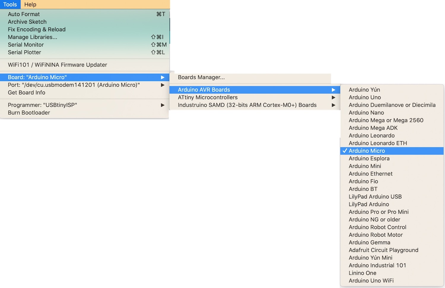
This is the link to the other person who had the same issue: link to page
This is their other side saying what the issues they were having which was the exact same as mine: link to page
After all of that I now have a working board! Woohoo
I then proceeded with the previous weeks assignment and managed to get the red LED on my board to light up. This was great fun as to see what not only does my board work but I have managed to get the LED to light up by using my laptop screen is amazing.
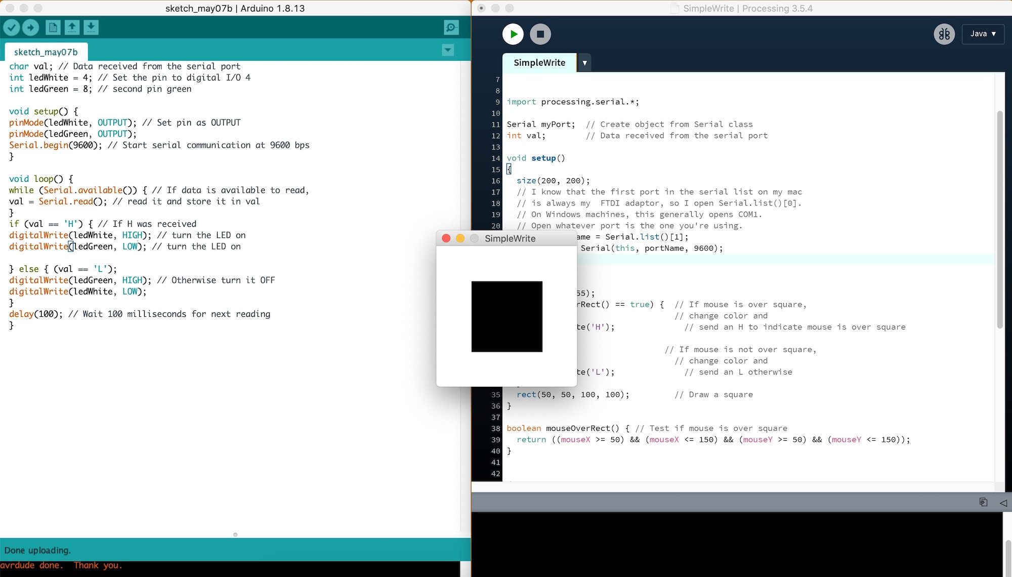
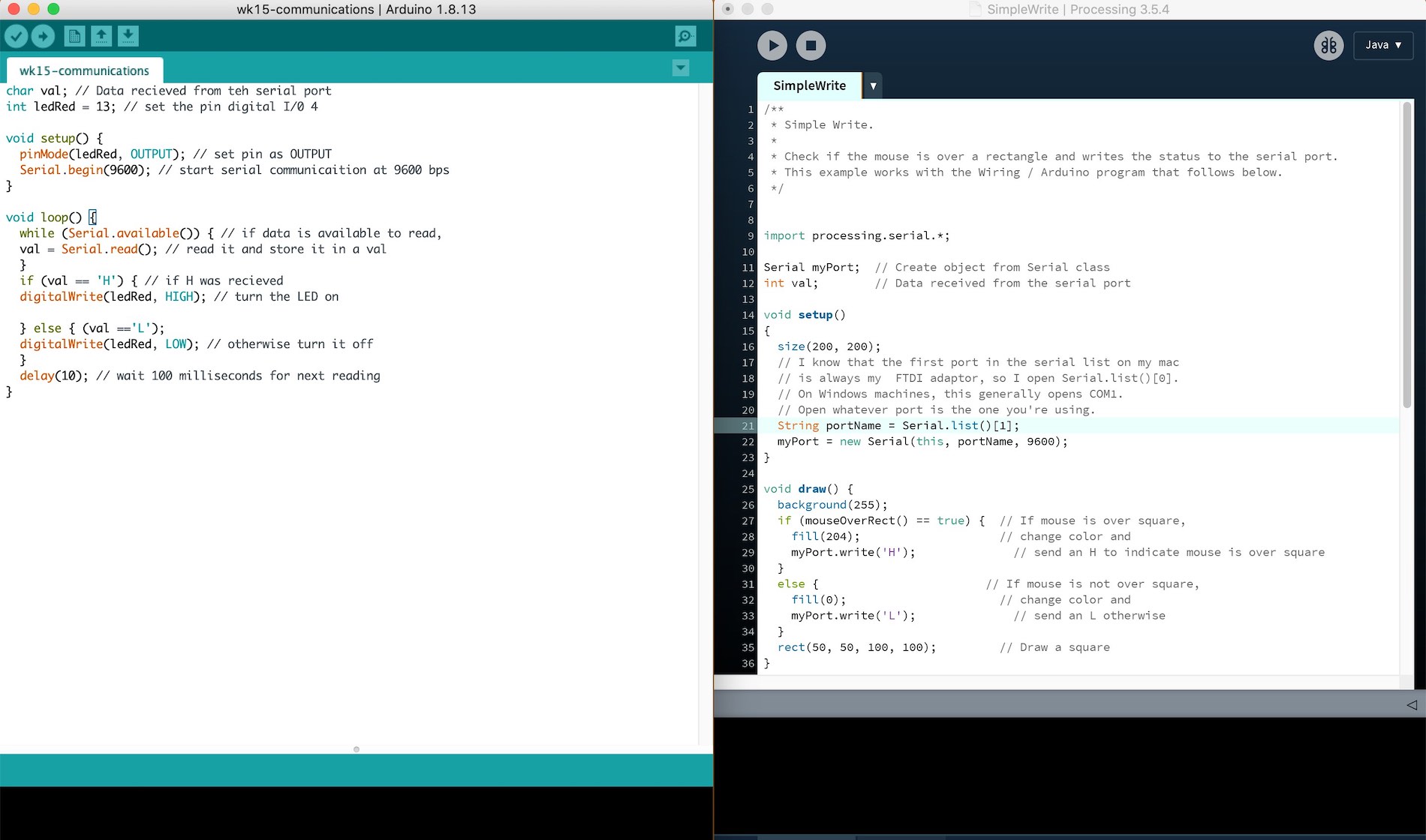
Here is the sketch below and a screenshot of what I wrote up for the two to work together.
      char val; // Data recieved from teh serial port
    int ledRed = 13; // set the pin digital I/0 4

    void setup() {
       pinMode(ledRed, OUTPUT); // set pin as OUTPUT
       Serial.begin(9600); // start serial communicaition at 9600 bps
    }

    void loop() {
      while (Serial.available()) { // if data is available to read,
      val = Serial.read(); // read it and store it in a val
      }
      if (val == 'H') { // if H was recieved
      digitalWrite(ledRed, HIGH); // turn the LED on

      } else {
      digitalWrite(ledRed, LOW); // otherwise turn it off
      }
      delay(10); // wait 100 milliseconds for next reading
    }
You will need to let the programme on arduino know what pin your LED us attached to and also also let the programme on Processing what port you are using [0] is the first one and then [1] is the second so for me I used [1] as this was the port my board was in.
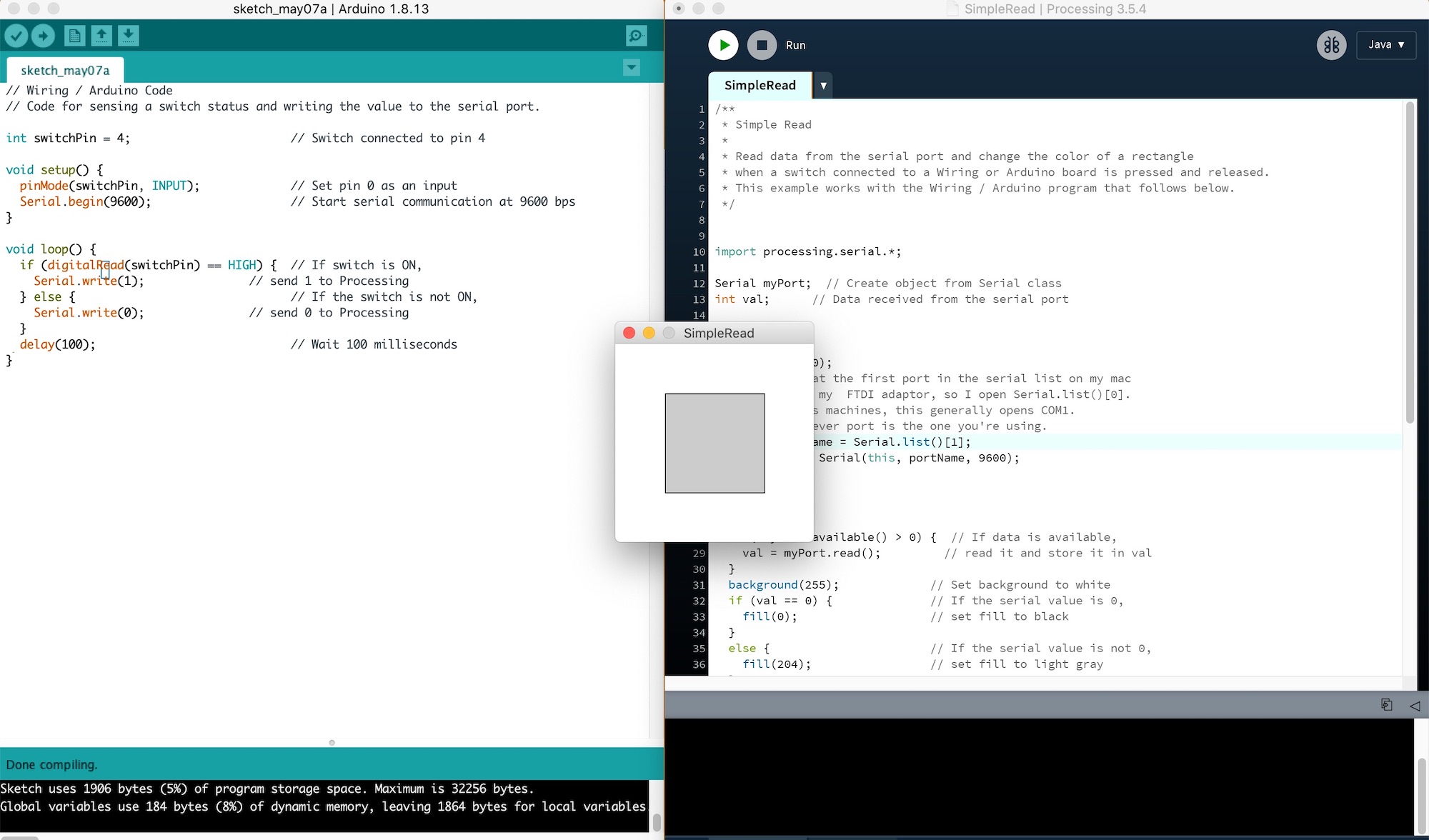
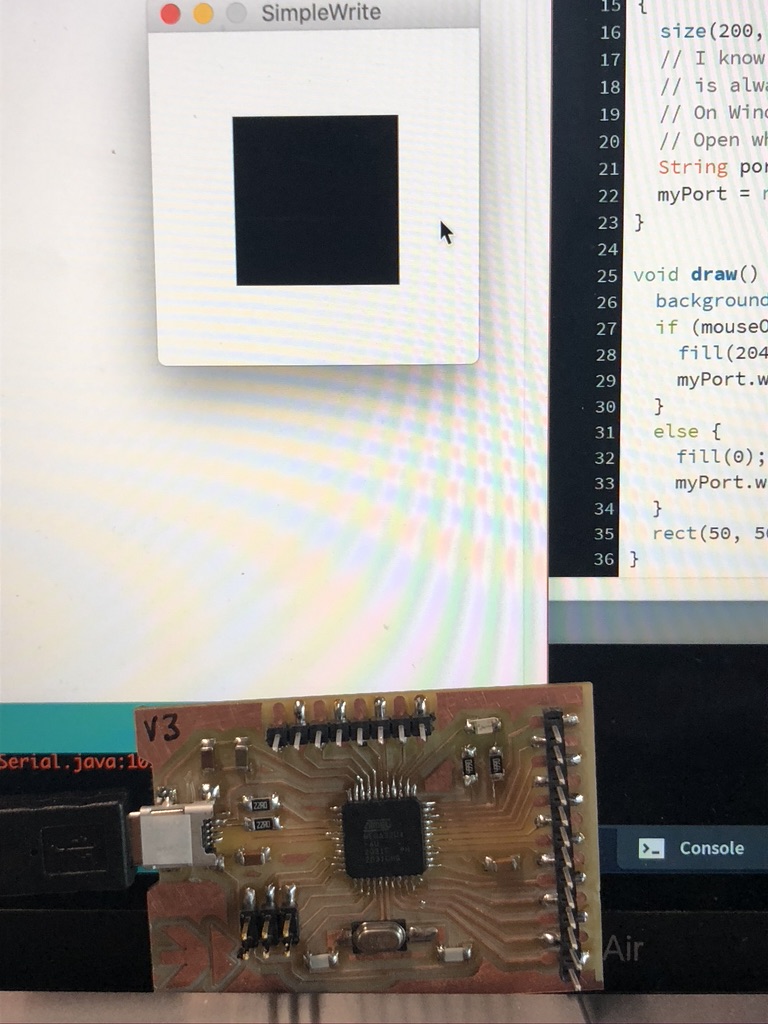
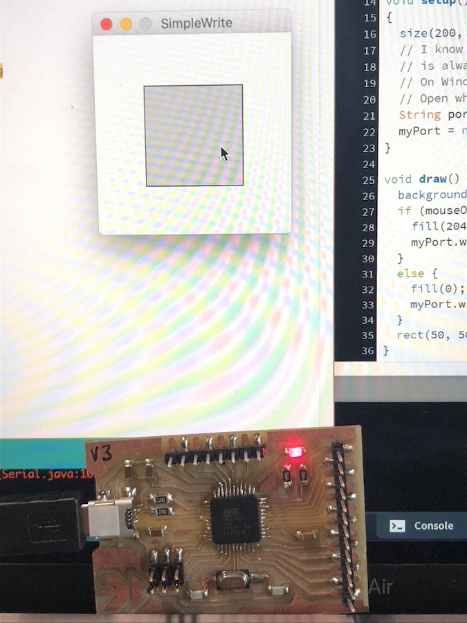
You first have to run the 'SimpleWrite' and then upload the programme on arduino to your board. You'll then see the grey/ black box come up on a separate webpage, then hover your mouse over the box which should then change from black to grey as well as the LED lighting up.
      char val; // Data recieved from teh serial port
    int ledRed = 13; // set the pin digital I/0 4

    void setup() {
      pinMode(ledRed, OUTPUT); // set pin as OUTPUT
      Serial.begin(9600); // start serial communicaition at 9600 bps
    }

    void loop() {
      while (Serial.available()) { // if data is available to read,
      val = Serial.read(); // read it and store it in a val
      }
      if (val == 'H') { // if H was recieved
      digitalWrite(ledRed, HIGH); // turn the LED on

      } else {
      digitalWrite(ledRed, LOW); // otherwise turn it off
      }
      delay(10); // wait 100 milliseconds for next reading
    }
      /**
    * Simple Write.
    *
    * Check if the mouse is over a rectangle and writes the status to the serial port.
    * This example works with the Wiring / Arduino program that follows below.
    */


    import processing.serial.*;

    Serial myPort;  // Create object from Serial class
    int val;        // Data received from the serial port

    void setup()
    {
      size(200, 200);
      // I know that the first port in the serial list on my mac
      // is always my  FTDI adaptor, so I open Serial.list()[0].
      // On Windows machines, this generally opens COM1.
      // Open whatever port is the one you're using.
      String portName = Serial.list()[1];
      myPort = new Serial(this, portName, 9600);
    }

    void draw() {
      background(255);
      if (mouseOverRect() == true) {  // If mouse is over square,
        fill(204);                    // change color and
        myPort.write('H');              // send an H to indicate mouse is over square
      }
      else {                        // If mouse is not over square,
        fill(0);                      // change color and
        myPort.write('L');              // send an L otherwise
      }
      rect(50, 50, 100, 100);         // Draw a square
    }

    boolean mouseOverRect() { // Test if mouse is over square
      return ((mouseX >= 50) && (mouseX <= 150) && (mouseY >= 50) && (mouseY <= 150));
    }


    /*
      // Wiring/Arduino code:
    // Read data from the serial and turn ON or OFF a light depending on the value

    char val; // Data received from the serial port
    int ledPin = 4; // Set the pin to digital I/O 4

    void setup() {
    pinMode(ledPin, OUTPUT); // Set pin as OUTPUT
    Serial.begin(9600); // Start serial communication at 9600 bps
    }

    void loop() {
    while (Serial.available()) { // If data is available to read,
    val = Serial.read(); // read it and store it in val
    }
    if (val == 'H') { // If H was received
    digitalWrite(ledPin, HIGH); // turn the LED on
    } else {
    digitalWrite(ledPin, LOW); // Otherwise turn it OFF
    }
    delay(100); // Wait 100 milliseconds for next reading
    }

    */
As seen above I used Luiz's board which is incorrect as this is not a board that I have made myself. I therefore got my final board and had a go with this and it worked yay! I couldn't for some reason get the led ont he bpard to light up via pin 13 but managed to get it to work by using pin 8 and attaching an led on a breadboard and a resistor. It didn't come up very bright but I am very pleased it did work as I was worried I had broken the board again.
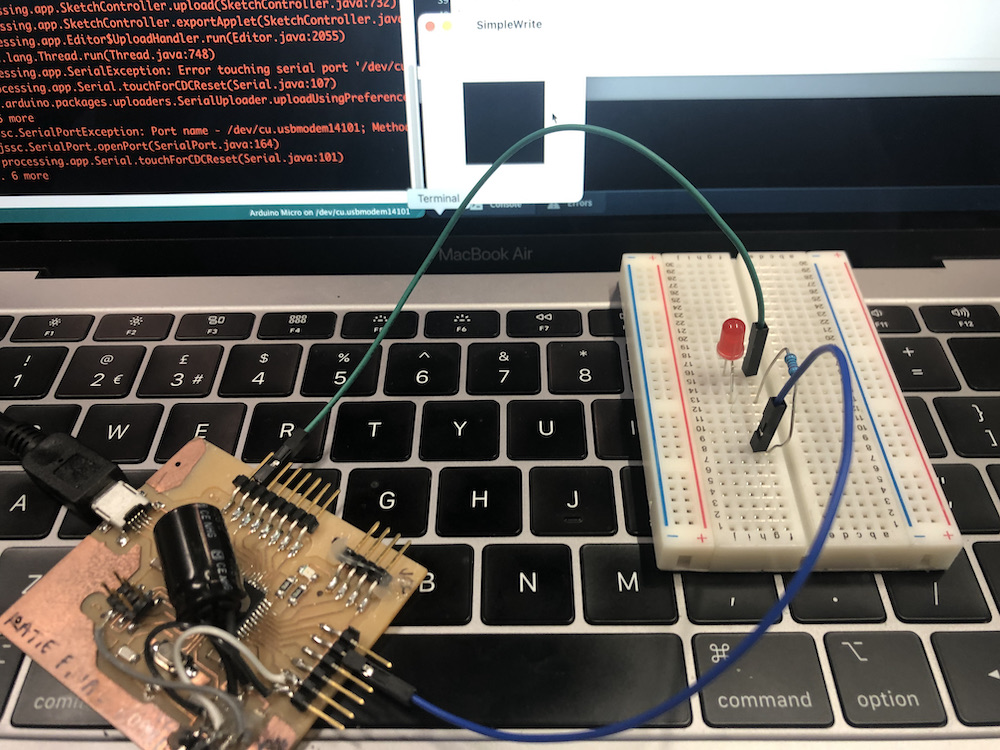
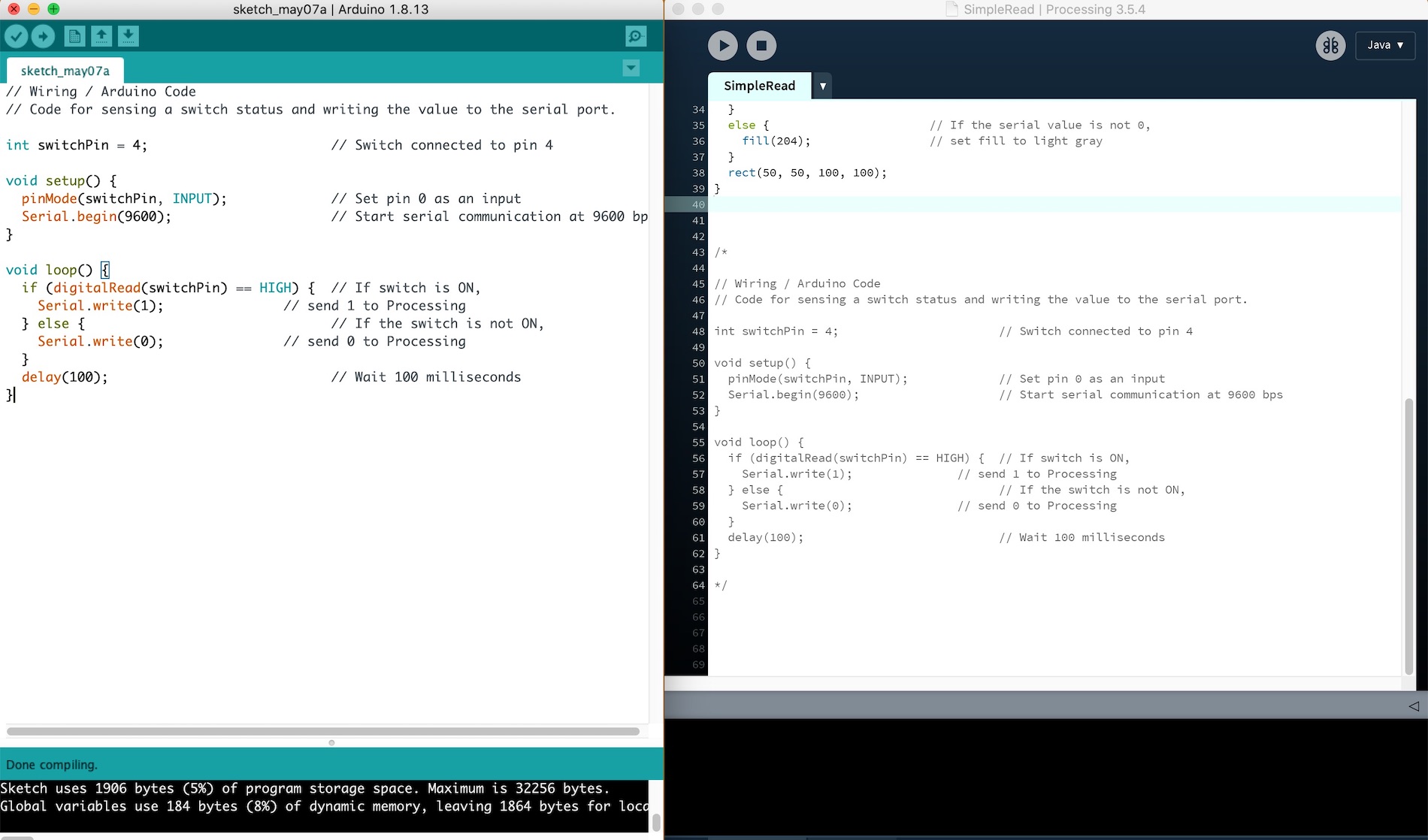
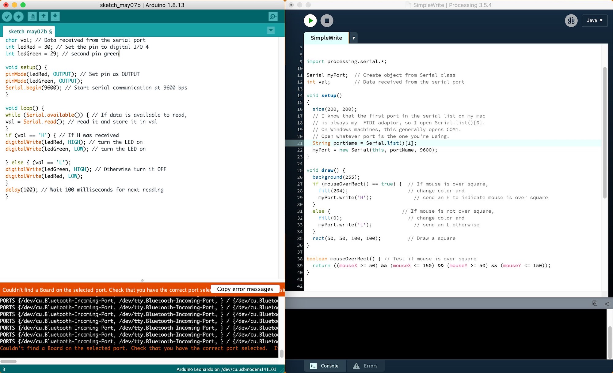
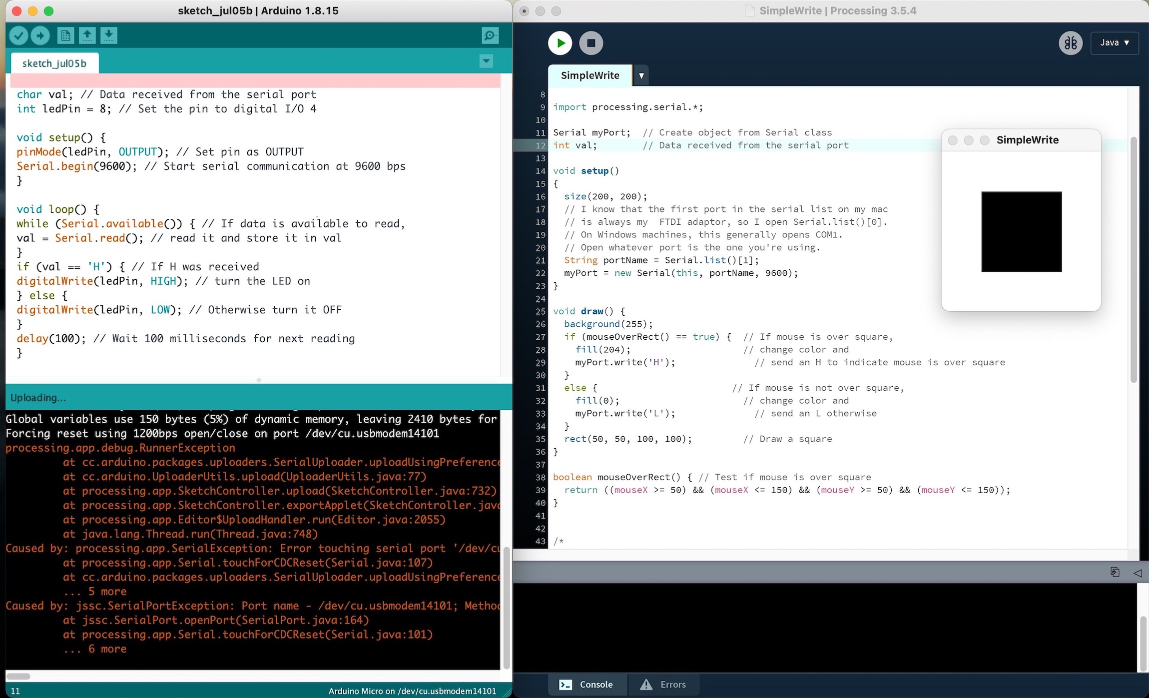
These are the two sketches Arduino (left) and Processing (right) which I uploaded to my board. For some reason this error message came up which you can also see in the video but it still allowed the led to work with my board. I was at this point just very placed with the outcome as I know that mt board hasn't broken.
  import processing.serial.*;

Serial myPort;  // Create object from Serial class
int val;        // Data received from the serial port

void setup()
{
  size(200, 200);
  // I know that the first port in the serial list on my mac
  // is always my  FTDI adaptor, so I open Serial.list()[0].
  // On Windows machines, this generally opens COM1.
  // Open whatever port is the one you're using.
  String portName = Serial.list()[0];
  myPort = new Serial(this, portName, 9600);
}

void draw() {
  background(255);
  if (mouseOverRect() == true) {  // If mouse is over square,
    fill(204);                    // change color and
    myPort.write('H');              // send an H to indicate mouse is over square
  }
  else {                        // If mouse is not over square,
    fill(0);                      // change color and
    myPort.write('L');              // send an L otherwise
  }
  rect(50, 50, 100, 100);         // Draw a square
}

boolean mouseOverRect() { // Test if mouse is over square
  return ((mouseX >= 50) && (mouseX <= 150) && (mouseY >= 50) && (mouseY <= 150));
}


/*
  // Wiring/Arduino code:
 // Read data from the serial and turn ON or OFF a light depending on the value

 char val; // Data received from the serial port
 int ledPin = 4; // Set the pin to digital I/O 4

 void setup() {
 pinMode(ledPin, OUTPUT); // Set pin as OUTPUT
 Serial.begin(9600); // Start serial communication at 9600 bps
 }

 void loop() {
 while (Serial.available()) { // If data is available to read,
 val = Serial.read(); // read it and store it in val
 }
 if (val == 'H') { // If H was received
 digitalWrite(ledPin, HIGH); // turn the LED on
 } else {
 digitalWrite(ledPin, LOW); // Otherwise turn it OFF
 }
 delay(100); // Wait 100 milliseconds for next reading
 }
    char val; // Data received from the serial port
    int ledPin = 8; // Set the pin to digital I/O 4

    void setup() {
    pinMode(ledPin, OUTPUT); // Set pin as OUTPUT
    Serial.begin(9600); // Start serial communication at 9600 bps
    }

    void loop() {
    while (Serial.available()) { // If data is available to read,
    val = Serial.read(); // read it and store it in val
    }
    if (val == 'H') { // If H was received
    digitalWrite(ledPin, HIGH); // turn the LED on
    } else {
    digitalWrite(ledPin, LOW); // Otherwise turn it OFF
    }
    delay(100); // Wait 100 milliseconds for next reading
    }
I also had a little play around with another sketch that I found on Elena Cardiel week17 assignment so I thought I would give it ago and it was very fun to see how this could actually work. I think in the future I would like to play around more with the visual side on the screen rather than having an external board controlling it.
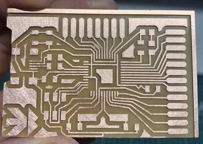
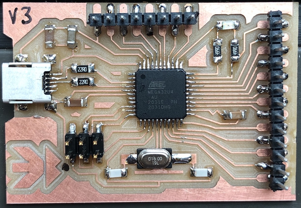
These are my traces and outlines for my final board, if you need Luiz outline and traces click here