
Link to Electronics Production Group Page
I followed Brians 'Building the FabTinyISP' website.
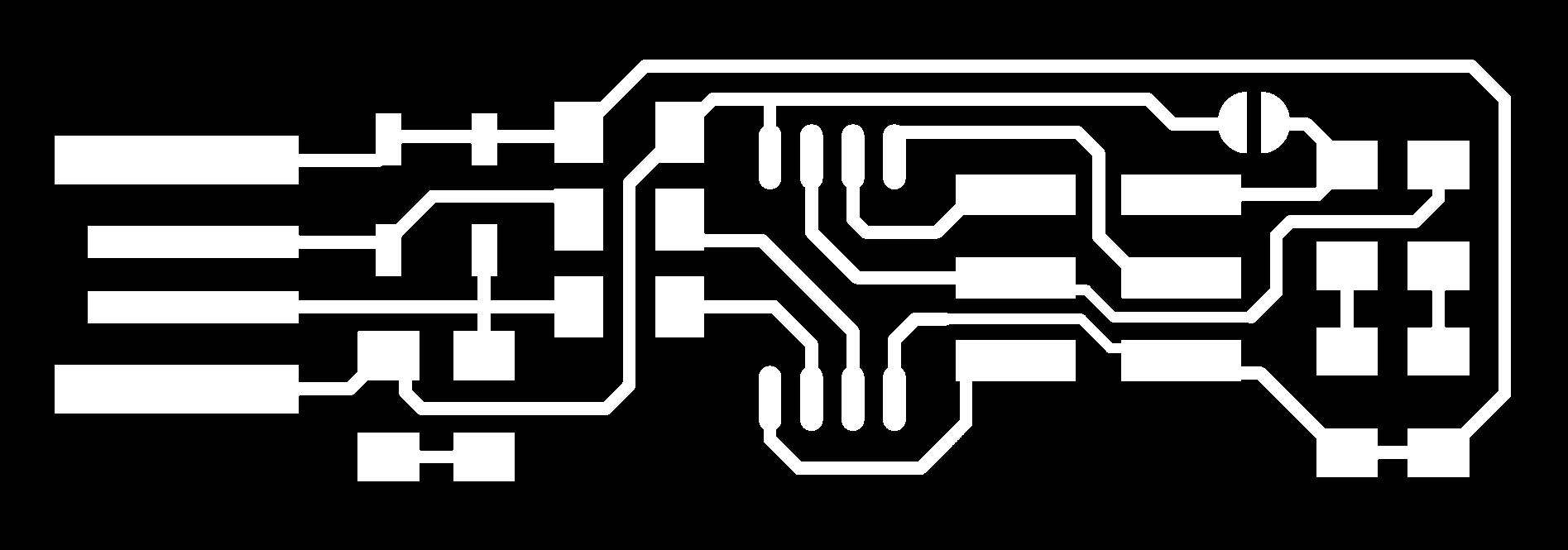
Before anything I started by getting the PNG files ready, the black lines will be cut away and the white will be kept. The first file of all the lines are the traces that will the copper lines to attch the electronics. The other is the cutout line for the board.
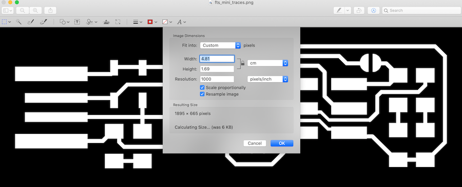
I checked the png of the two png files to makesure they were the correct size which was told on Brians website. To do this you go into 'Tools --> Adjust Size...' this will take you do the page where you can check the 'Resolution'. Check that the drop down is in 'pixels/inches' or 'pixels/cm' as this will change the outcome of the png.
Download the PNG files here:
To open up mods which is a web interface, you have to follow a few steps to get to the correct area for your machine. It tells you on the screen what to do, but you start by right clicking and then it come sup with different options. Follow the steps below to get to the 'roland srm-20 PCB' webpage.
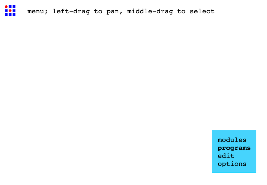
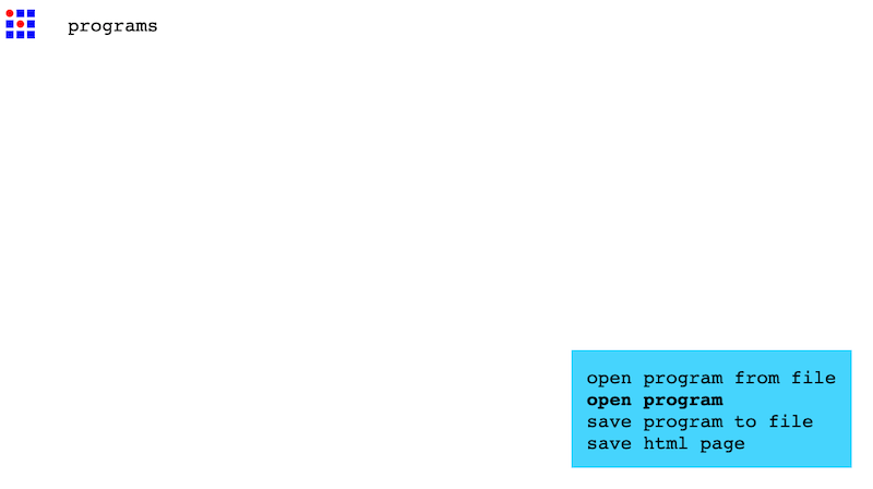
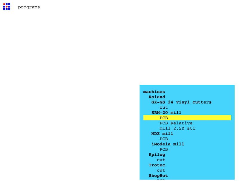
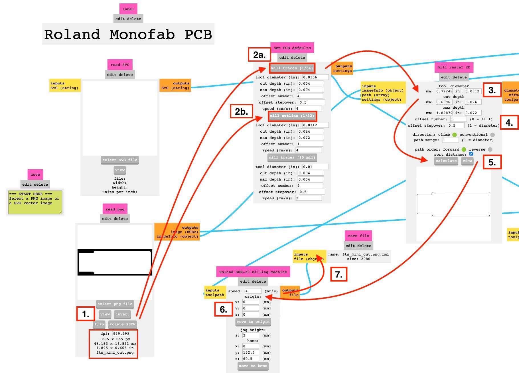
This is the webpage for mods which I used to cut my board out. I have made a list of the stages you shuold take to get to the end outcome, to the right handside of this page there is also more information about what is happening behind mods to get the correct files so that this peice can be cut out correctly.
Be aware that these stages are for both the traces and the outline, you have to make two different files for these two cuts. - - - Follow 2a for traces cutting and 2b for outline cutting.
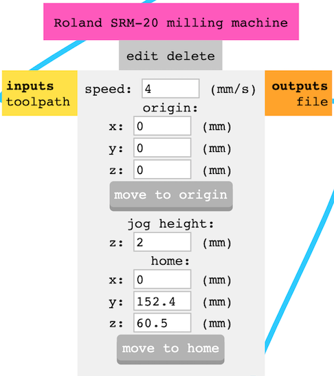
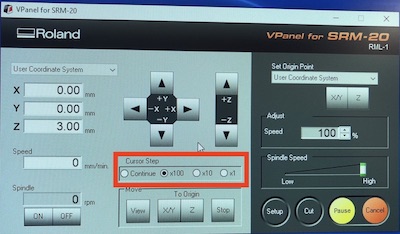
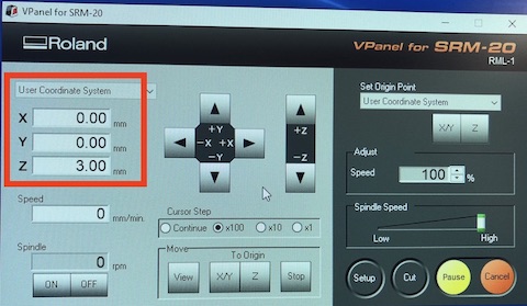
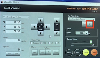
This is a zoomed image of setting the origins to 0 to show you the numbers but also the 'jog height' this is the height of the tool when it is moving around the material when cutting. This must be over 0 otherwise it will scatch the bed material and damage the tool bit.
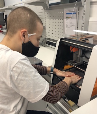
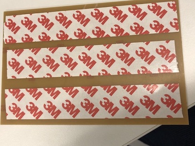
To start with you choose the board you are wanting to cut, you then place some double sided tape to the back of the board WARNING do not follow me here as this didn't work for my printing and I made my tape go the other way the second time. It will make more sense later on this page when I start milling the board.
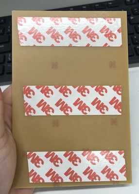
You then need to then peel off the tape backing and press down into the sacrificial board, both these items need to be very flat as this will determain the final outcome of your print. I madesure there was no bubbles in the tape and then when I pressed it down I made sure it was as flat as it could be by placing a flat board over it to check there was no gapping.
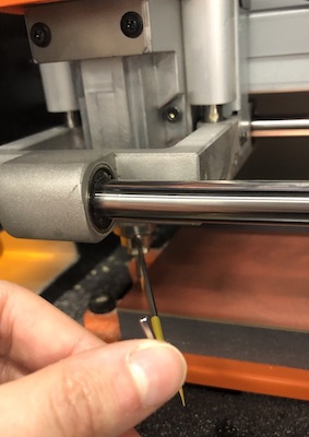
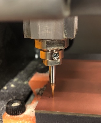
Placing the tool into the machine you have to be very careful not to hit the bit end on the edge of anything or drop it as they are so delicate they can break very easily. Then you must be sure not to over tighten the grubscrew which is on the chuck where you place the tool bit in. By using the allen key (as shown in image) you then can't put too much pressure onto it as it is so long so you wont break the thread but just be aware that this is something you should be careful of but do be sure to tighten it enough otherwise they can fall out... stay tuned.
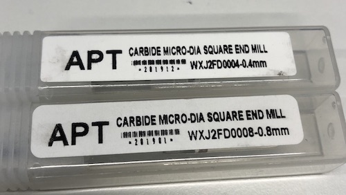
I used a 0.4 mm square ended milling bit for cutting out the trace and a 0.8 mm square ended milling bit for cutting out the main edge.
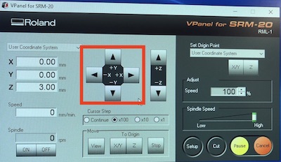
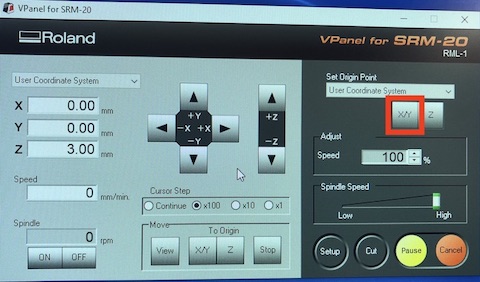
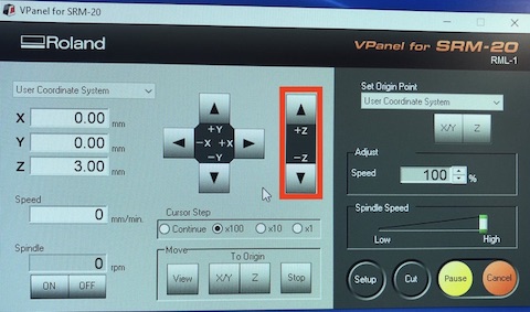
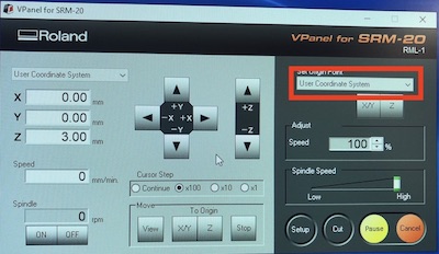
Overal look at the v-panel
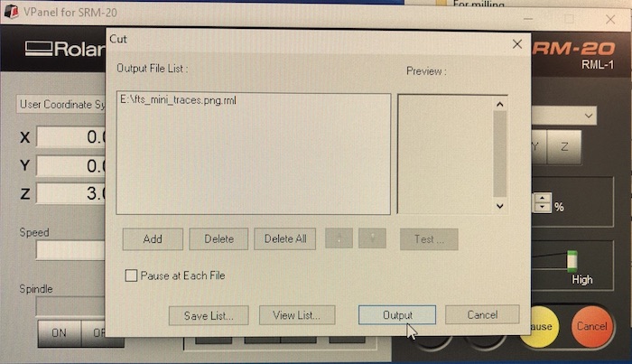
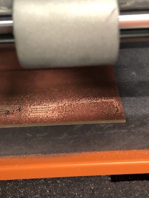
First attempt cut the outside and part of the inside but then didn't do the middle main traces.

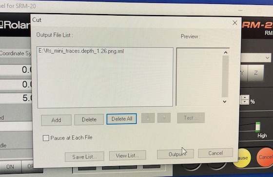
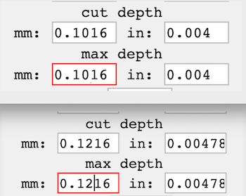
I changed the depth of the cutting setting in mods so that the machine will but it deeper. I changed it by 0.10 to 0.12 which seemed to work in the end but...
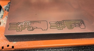
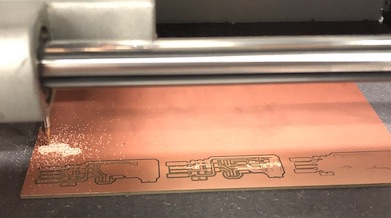
It still wasn't working and we couldn't understand why, I thought I might have been because of the way I had attached to the bed with the tape. So I decided to change the tape direction on the board and place it on the bed in the middle rather than right on the edge.
Putting the tape the right way around and replacing board into the middle of the sacrificial bed.
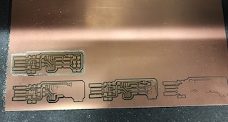
By doing these three changes of the depth in mods, moving the board and changing the tape this seemed to work as board 4 came out very nicely!
I then moved onto stuffing the board which I think is the best way to describe soldering the electronics on.
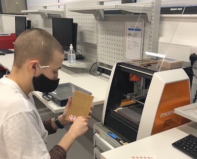
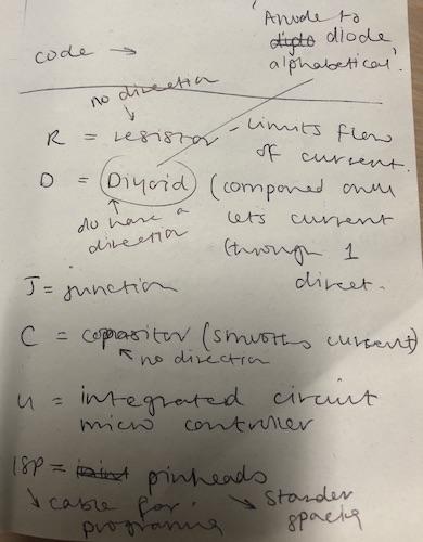
I picked up all the pieces that was on Brian lists in his document and I already knew that they fitted onto my board as that was one of the first things I did at the beginning. I then placed them of a sheet of paper as shown below with what they are, how many I needed and then the componeted they are connected to. As this was my first time in seeing most of these items I was struggling to rememeber which one is which. I was also struggling to remember what one needed to be the correct way around and what one is more sensitive to heat.
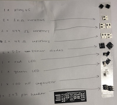
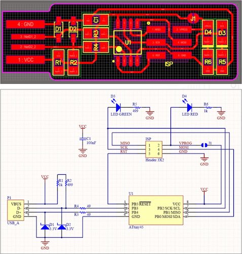
So to understand where everything went on the board I had made, Brian had an image of the board which looked like the board but with different lettering which is shown below. Then another image called a schematic and this tells you what direction the component is meant to go also what each letter means in the first image. I made myself a cheatsheet so that I could remember what piece is as in the schematic they are called other names, this is the image above.
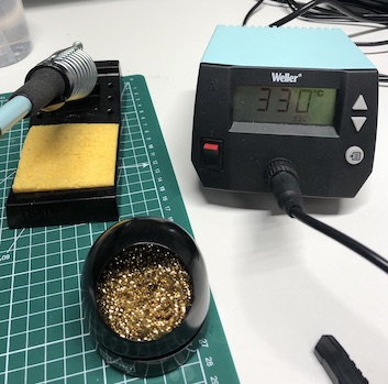
Right so how to solder, at the Wednesday meeting Niel did show us a little on how to solder. The jeneral jist of it is that:
Me doing the beginning of my board, Andrew was with me as I was doing this so got me to do the ATtiny45 first so he could see how I was getting on. I really like soldering, its like following and 3D pizzle but you have to lock the pieces into place and the outcome is a lot more fiddly but worth it.
Once I had soldered everything I had a look at my board and thought I had placed the green LED the wrong way around so I took it off and replaced it with a new one and flipped it around.
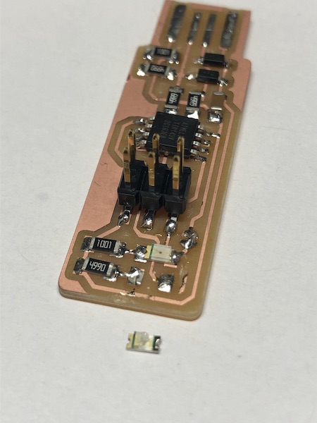
I finshed off by soldering the USB area this makes a better connected for the PCB to the USB port. Also I soldered the junction on the board which will be broken later on when I turn the board from a programmee to a programmer.
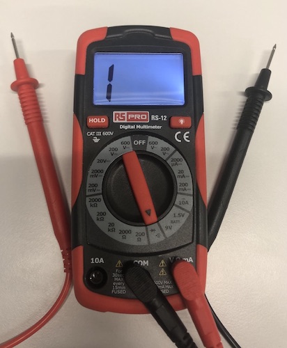
The next step is to see if this is all working, here is what I did:
I used a multimeter which is the photo below, this makes a buzzing noice when there is a connection and it also goes through LEDs which is perfect for this. The black lead is the ground so I can test that everything is the correct way around as well as is they are working around the board if there are any short circutes.
Everything looked and sounded good so then I loved into making a second board as I wanted to do more soldering, milling and overal thought just in case the first one didn't work I had another chance.
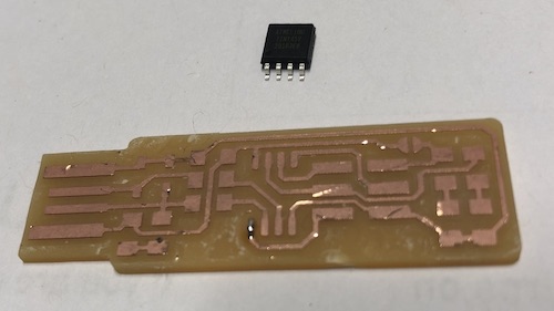
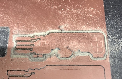
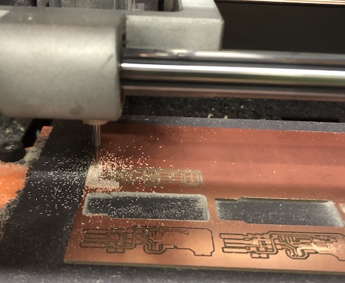
As you can see from the photos something went very wrong! The first image is my board with the cutting out of the tracers not working at all, and the second image is the milling bit which I had broken as I was milling. What happened which I had mentioned above is that I didn't tighten the grubscrew enough when putting the tool into the chuck. I got a very lovely vidoe of it falling and my stomache went as I saw it in real time... but it happens and lucky we had another bit to use and Jonny had cut his boards.
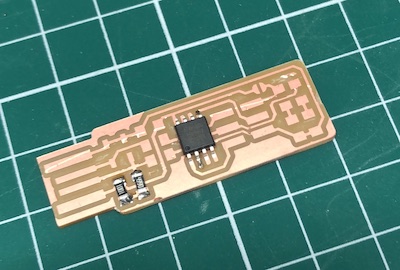
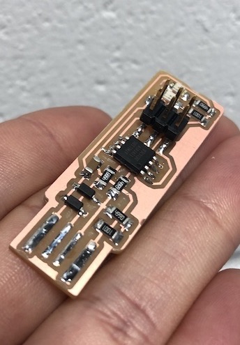
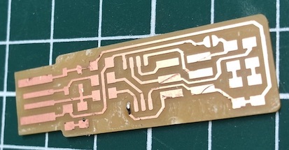
I tried it again and it all came out well, I also cut away the excess copper but I used a scalpel to do this and I didn't want to fisk braking another bit. (see image below)
I couldn't find the ISP so had to wait till Andrew was back in to help me find it.
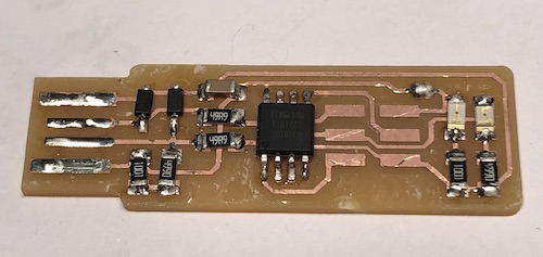
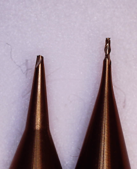
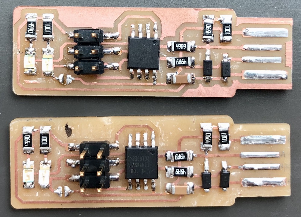
Image 1 - full
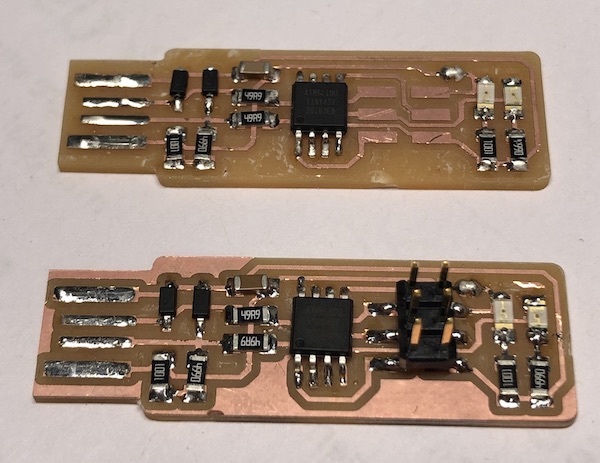
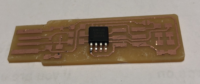
Image 2 - using a microscope
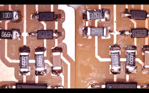
Image 3 - using a microscope
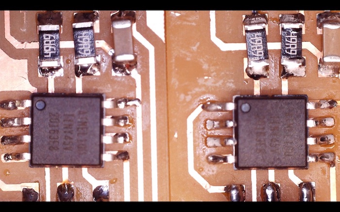
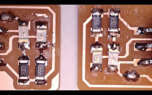
Image 4 - using a microscope

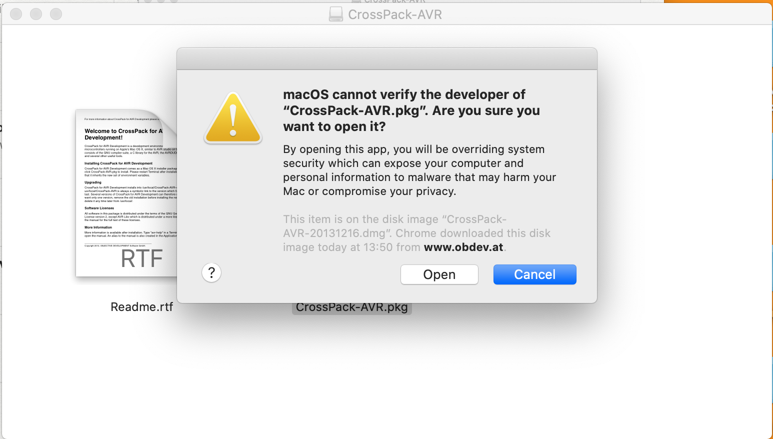
I downloaded CrossPack but Mac has a software called gatekeeper in it that wont let you open downloads if it doesn't trust it. To get around this you need to right click on the download and press open.
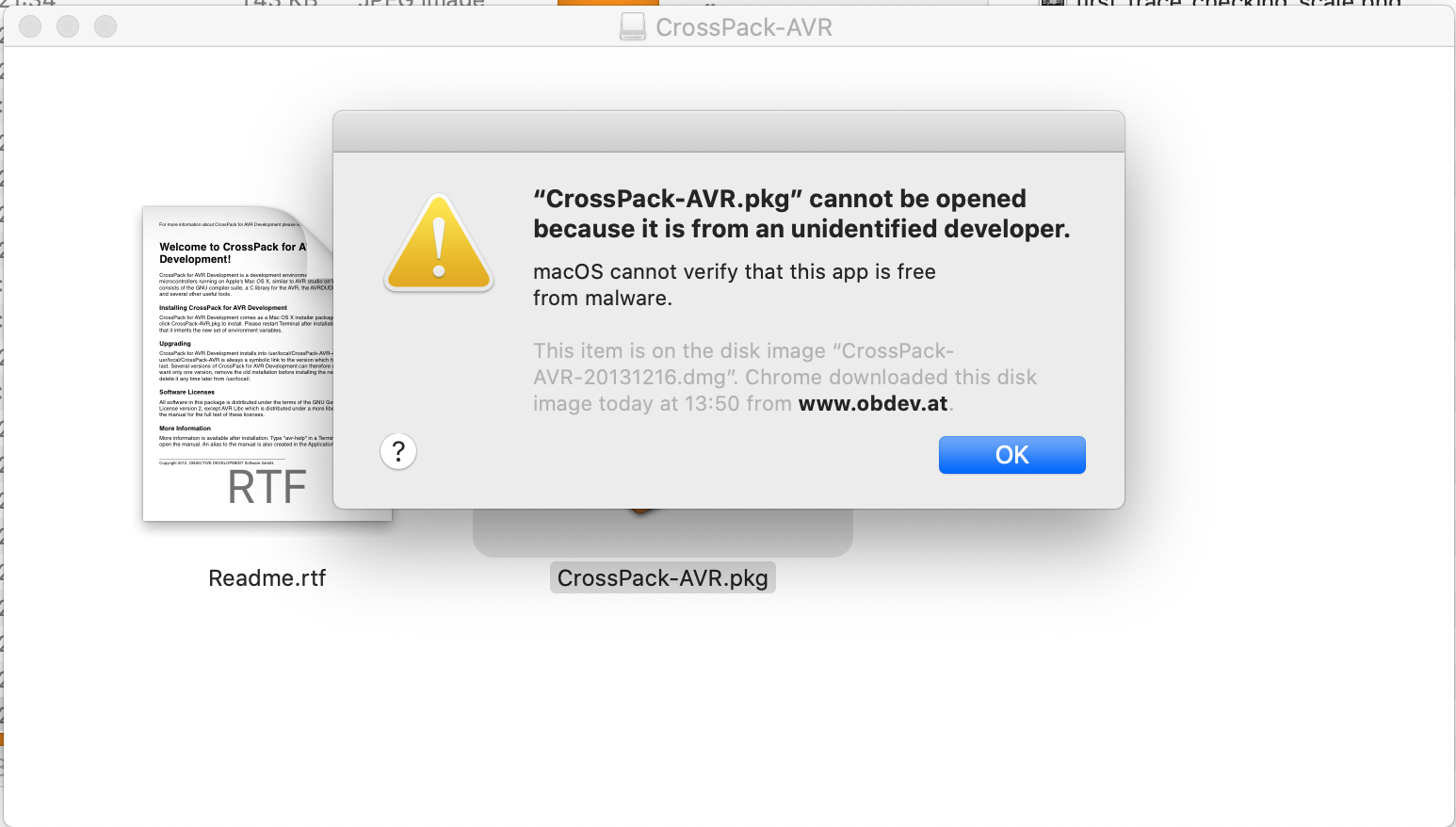
This will then open up and you need to click open, this means that you have gone around gatekeeper and it has seen you are clever and know what your doing and it will let you through.
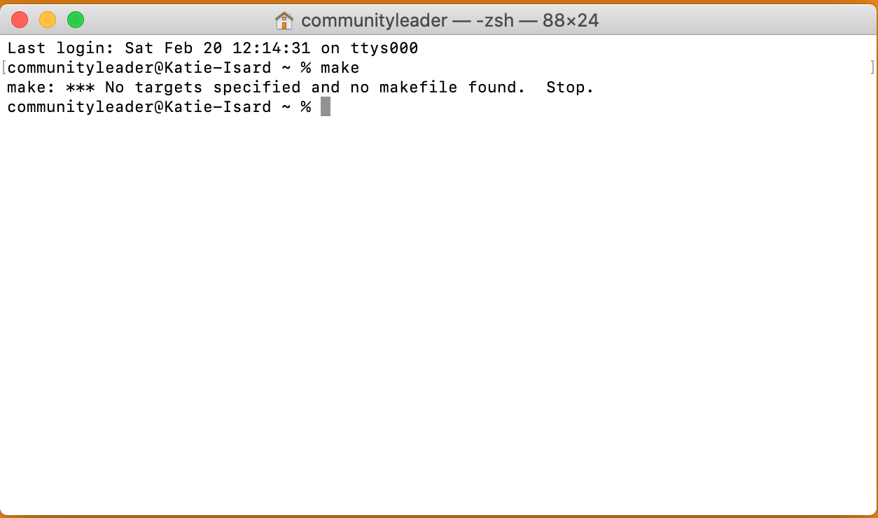
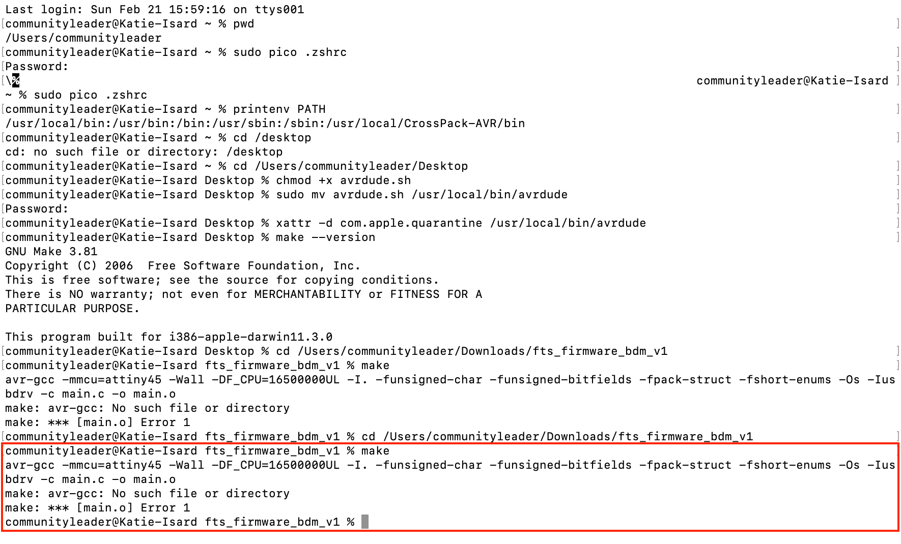
By typing in 'make' into terminal this showed me that it understood there was something new I had downloaded. I then realised the error was because I hadn't told terminal where the download was as it was still in 'home'. So needed to 'change directory' = cd then then paste to downloads as that was there CrossPath is.
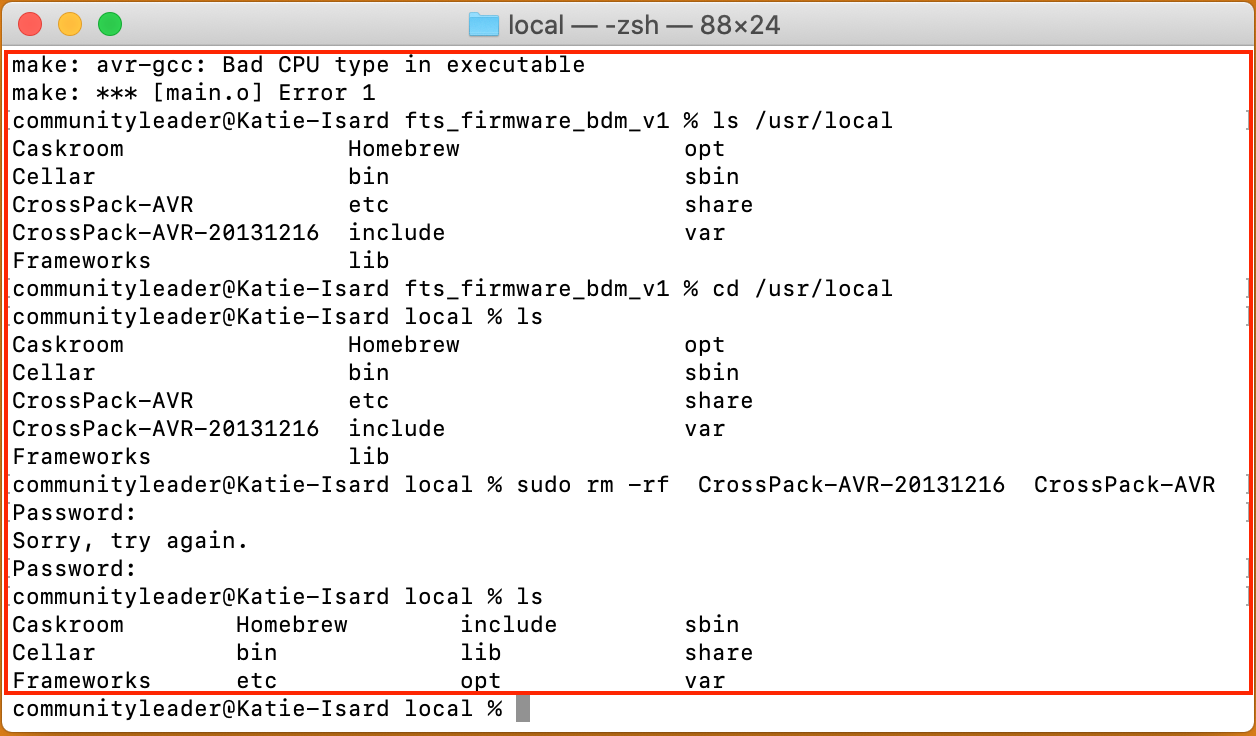
There was an error so I processed to google thins error to see what had gone wrong, this is when Andrew saw that CrossPack works on 32-bit and not 64-bit so this software wasn't going to work for me on my MacOS.
So this is when google came in and really helped, we found a website that gave me step by step instruction on what to do.
Follow this link to the website so you can do the same as me and follow their instructions. This is instead of installing CrossPack: MacOS 64-bit Toolchain
Alot if this I found very confusing and had to take my time to get my head around it, if I'm being honest I'm still not quite sure what each step means but I do understand what I did in each step which is a positive. All I would say is take each step at a time and and makesure that if it isn't working just restart terminal this saved me a lot during this journey.
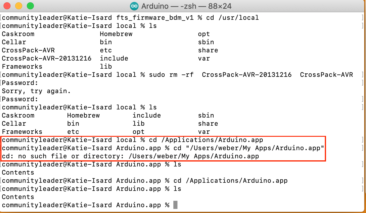
This is me uninstalling CrossPack and double checking by pressing 'ls' which is showing me the list of items I have in that directory I am in. This showed me that CrossPack has now left my directory as I wanted.
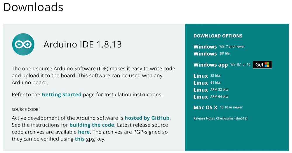
Follow the steps online I then downloaded Arduino as this has the same ability to run 'make' which is what I need to run my PCB board later on.
This is to see see if I had added the AVR in my toolchain which as you can see I didn't but I didn't notice this last time and therefore at the end this wasn't working in the next step I'll explain why it hadn't come up in the tool chain. Open a new terminal after this step so that it can refresh itself.
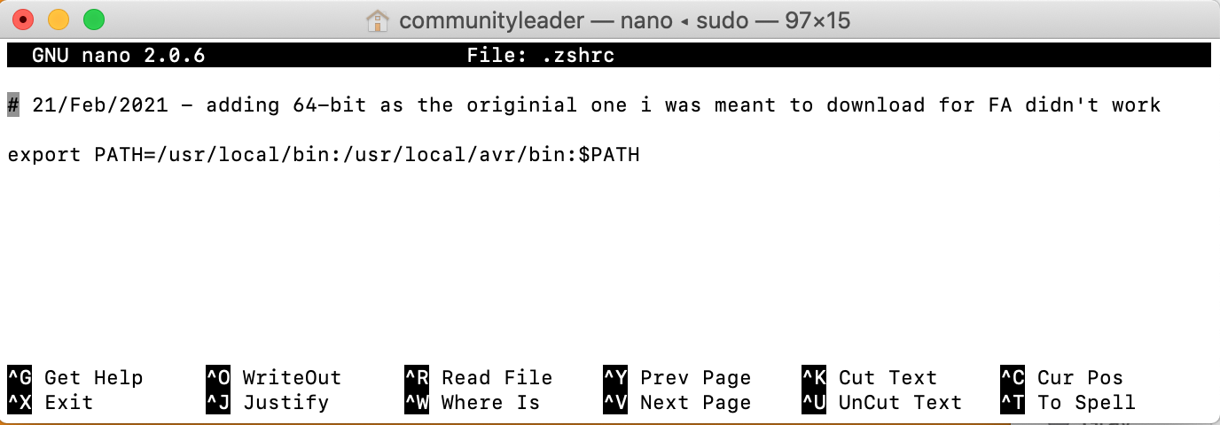
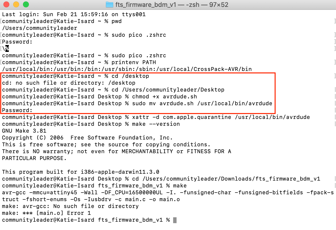
This is me adding the AVR link to my toolchain, this is where you place some of your items that you have downloaded so that they are remember by your terminal. I forgot to add the link to this section so the rest of it didn't work which is why at the end I was struggling. Sudo is basically overiding all the setting of the termnial so you can go behind, but it can also be very dangerous as you can delete all your information you have in your cloud.
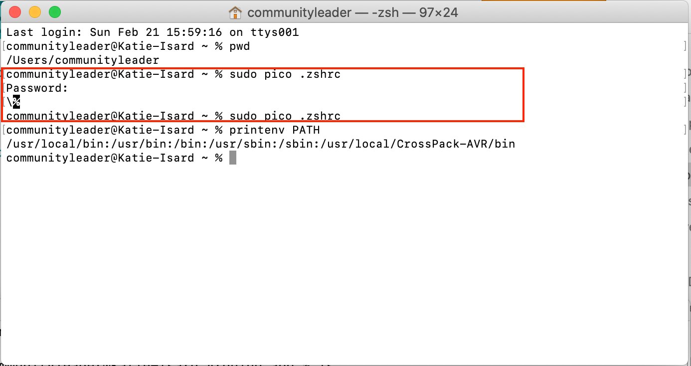
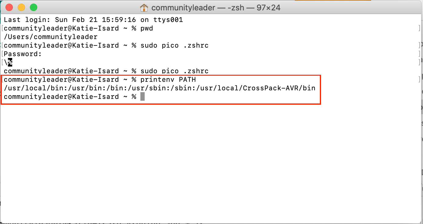
This is where I should have double checked the AVR was in my path but as you can see it is not so again I had to go back and add it to the previous stage and then it came up in thie stage.
This step (do double check the website MacOS 64-bit Toolchain ) but this is so that the Arduino can find what you are doing in terminal.
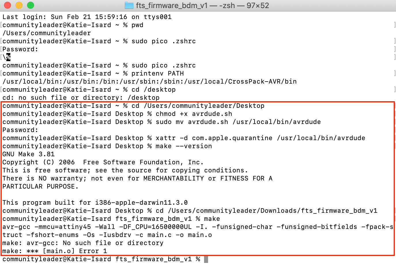
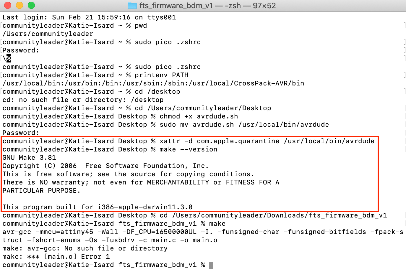
So with macOS and this 'make' doesn't actually work very well so I have to use 'make --verison' which you can see in this screenshot.
This is where I realised I had done the presvious stage wrong when it came to the path and putting the link in pico, but after I had done this it worked in step 7!
WOOHOO I have now done the whole processes which could have just been 'CrossPack' but we are here now and I can't complain too much.
Tip it is always good to just chekc what terminal is saying, as you can see in the right hand screenshot there is some writing in pink. I know this is fine as Andrew says it is and other have done this before but do always read this areas as this can give you some information that you might not have known.
So this whole step is just the 1 on Brians page which is to do the 'Software Installation' because Brians website is old the software that he suggests now doesn't work on the lastest MacOS as the old one was 32-bit and we are now using a 64-bit.
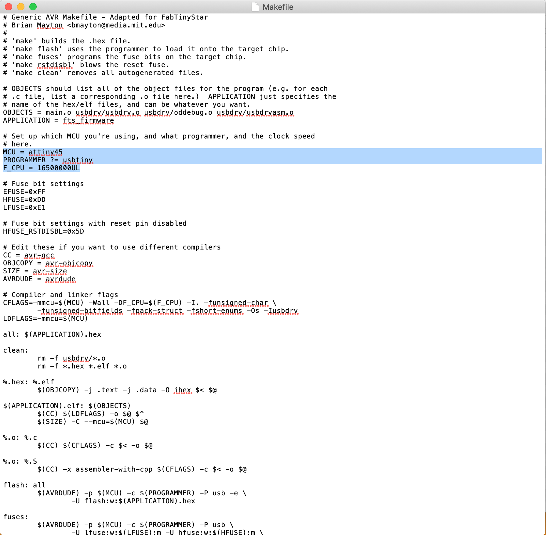
Checking that in my Makefile that it says:
This is to set up the programmer that I will be programming my board with so if it has a ATting45 chip then this doesn't need to be changed but if it has a different chip I will need to update this area of the doc.
I started by just plugging my board into a USB port to see if anything would happen, and there was a light! Unfortunatly turns out that doesn't really mean anything and that I had a very long road ahead to see if my board was actually going to work...
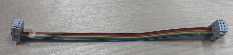
Getting the ribbon heads the correct away around is a tricky part and by looking at Andrews I managed to figure out how this would work. To get it to clip together was very hard so I used one of our clamps to click the female header together with the other part with the metal spikes. You need to make sure that when you are clamping it the female headers are facing in so that the lines match up with the correct pins. Hope that makes sense.
Future Katie here: this ribbon cable was great and I ended us using my programmer and ribbon cable most weeks to programme my future board! Make sure you get this made correctly and that you keep it, I also added little black dots on the female headers to show which pin was teh GND.
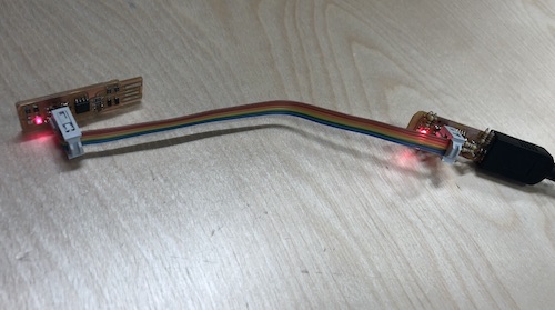
I used my ribbon cable to connect Andrews PCB to mine to programme it, to get this to work I connected Andrews programmer to the computer.
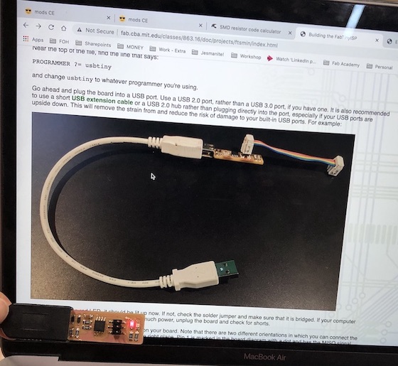
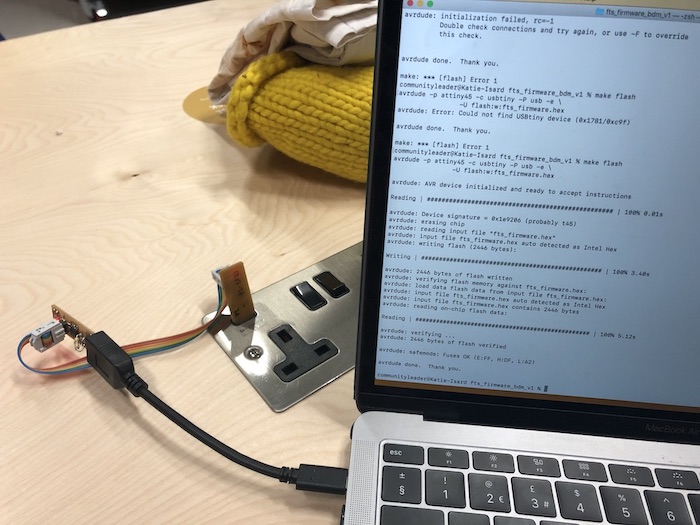
Following Brians instructions I placed my board on the left side (if looking at picture) and then the programmer closest to the computer. Both lights came of which made me happy (whether is a helpful part or not) making sure they are facing the same way (USB port towards computer) I then ran the next step...
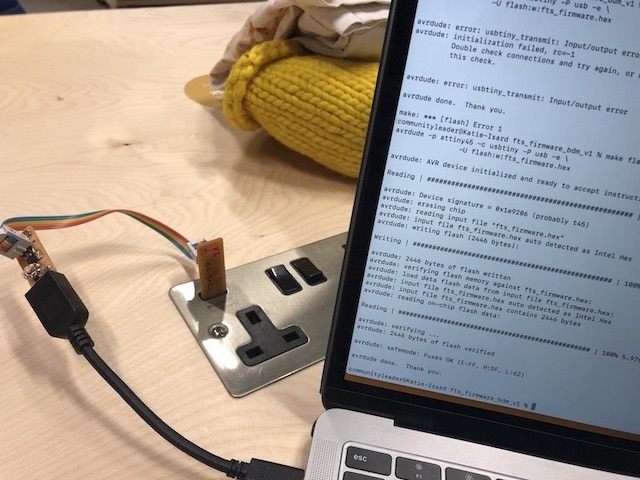
This is the command you put in terminal 'make flash' to see if your board is correct, it wasn't working as you can see in the next photo but...
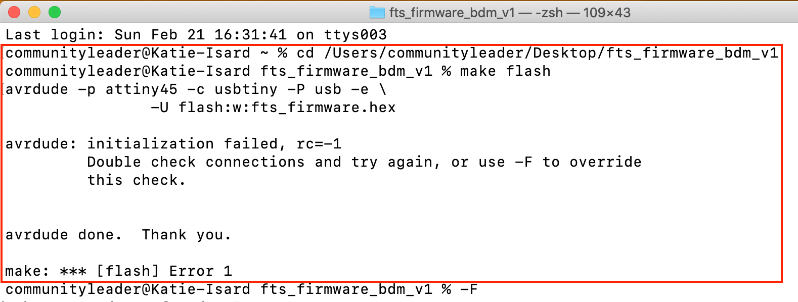
Andrew then looked it up and realised we needed to plug both the USB into a socket so then I ran 'make flash' and IT WORKED!
I then did it on my second board and THAT WORKED TOO!
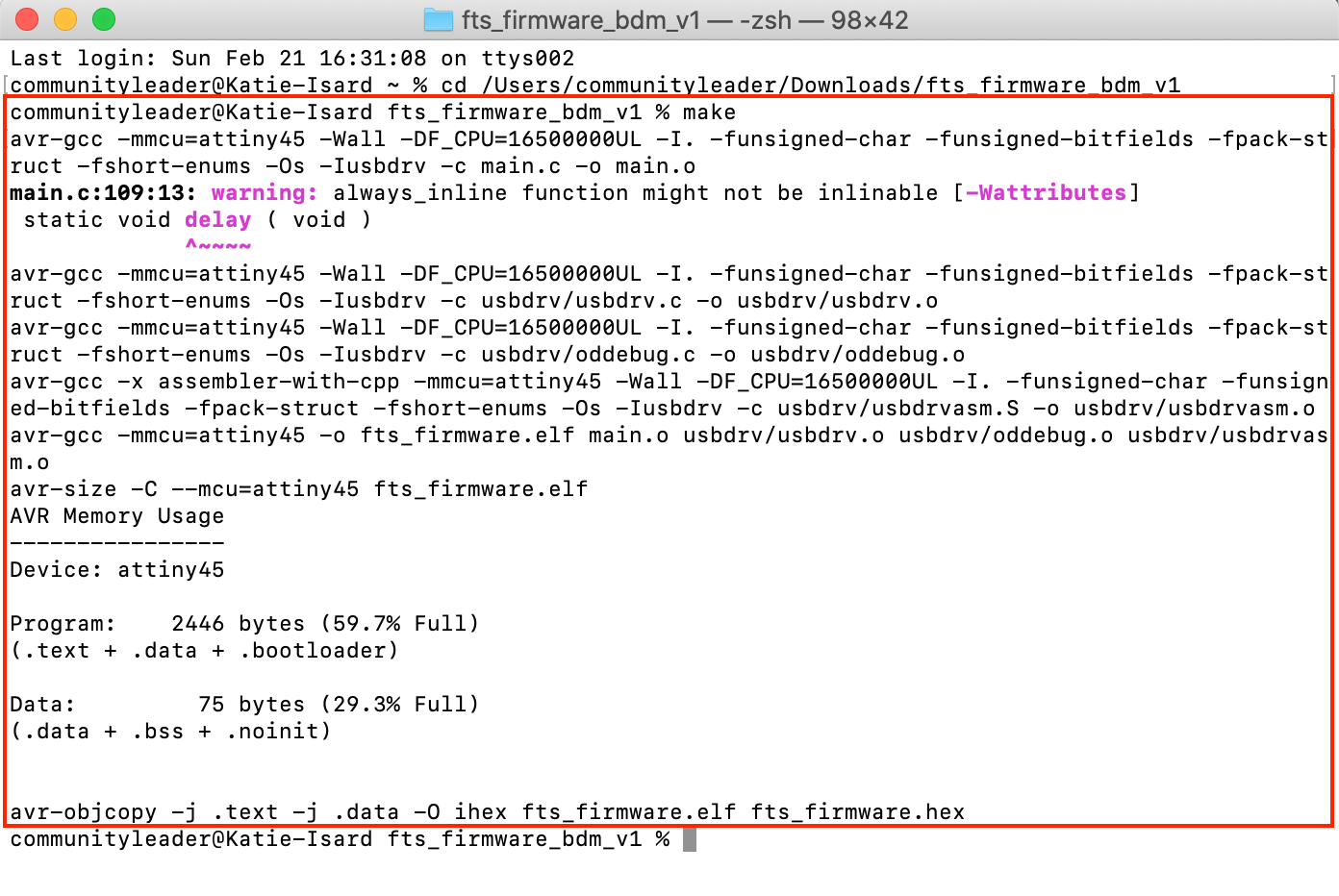
This is what terminal looks like when it has gone to plan!
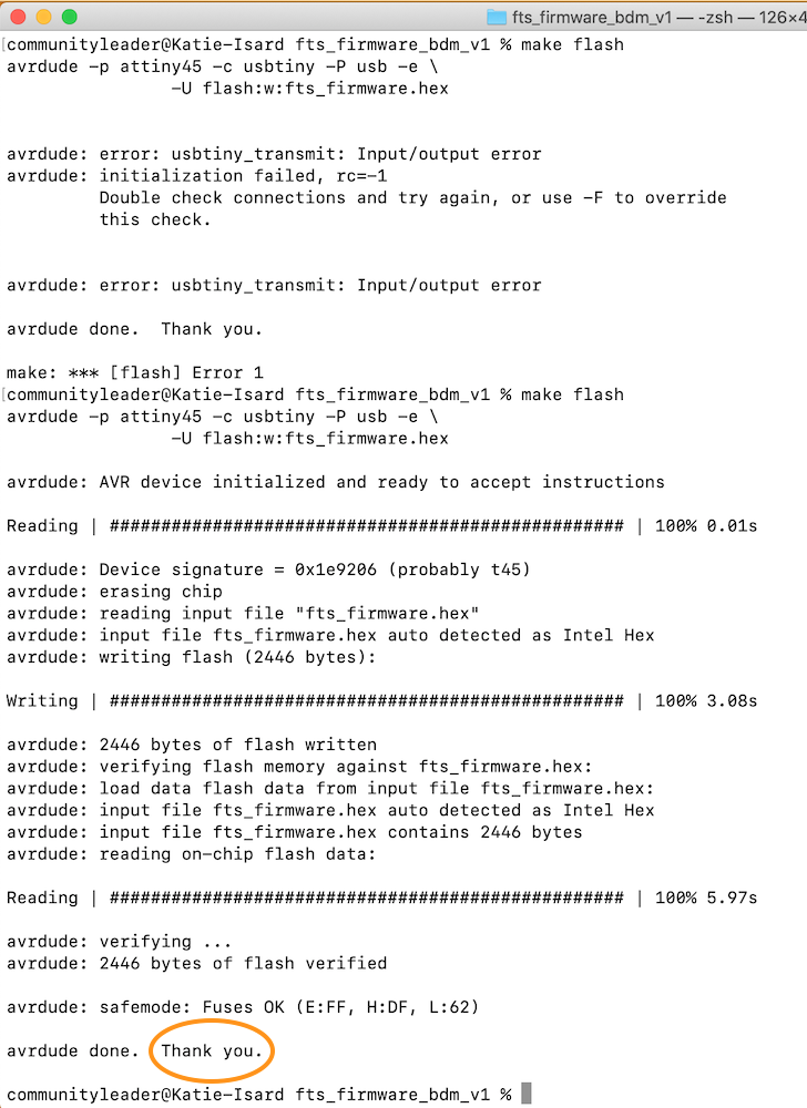
No thank
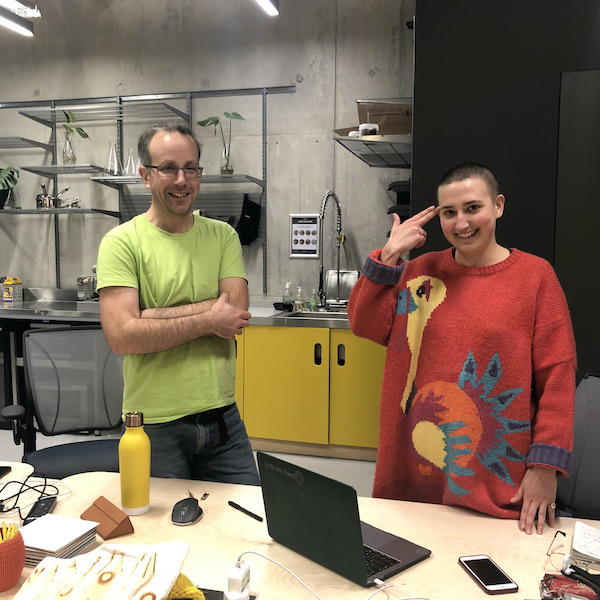
Andrew and me realising after 4 hours how to get this sorted! I think you can tell it has been long but deep deep down we are smiling and very happy it has work! wooohooo :)
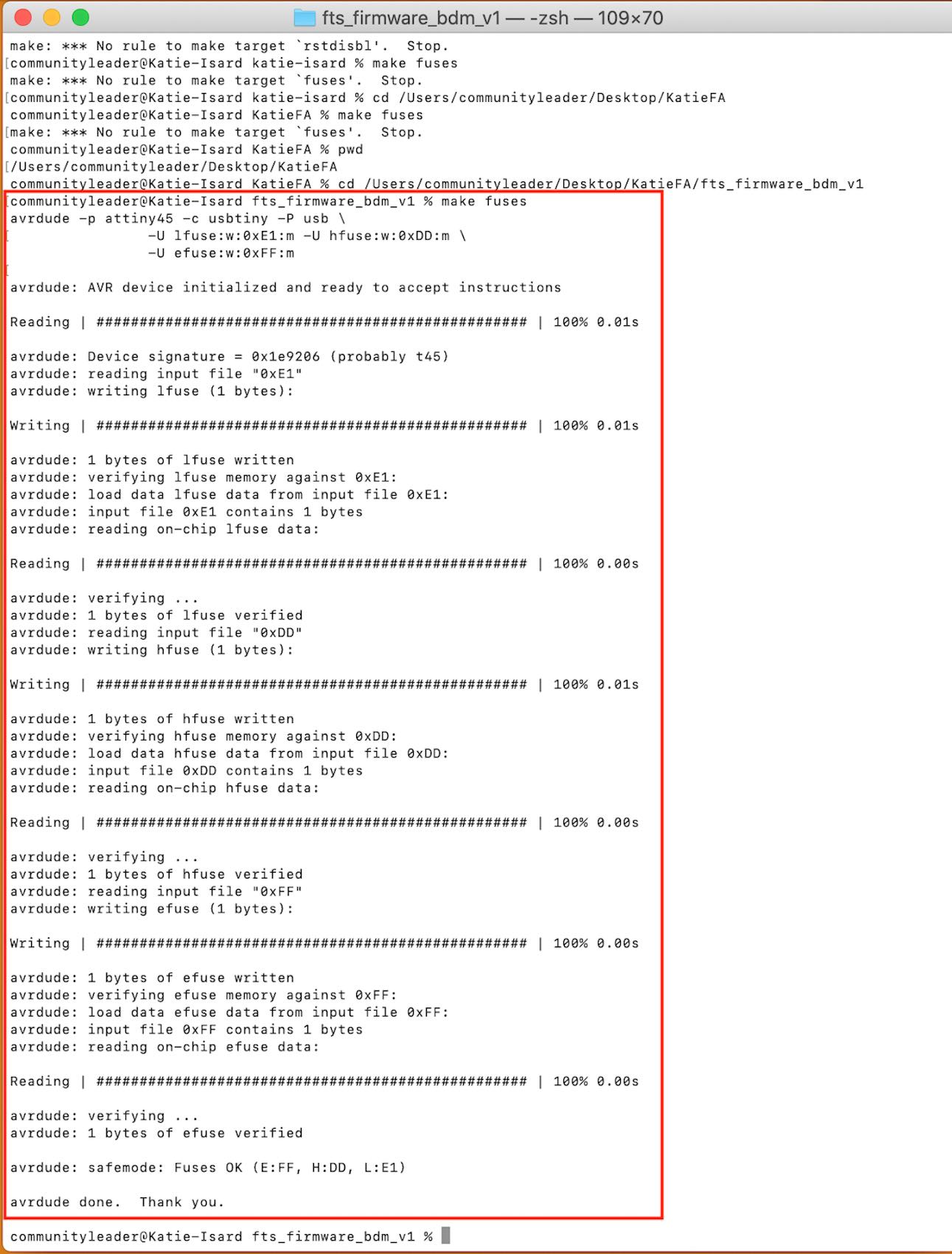
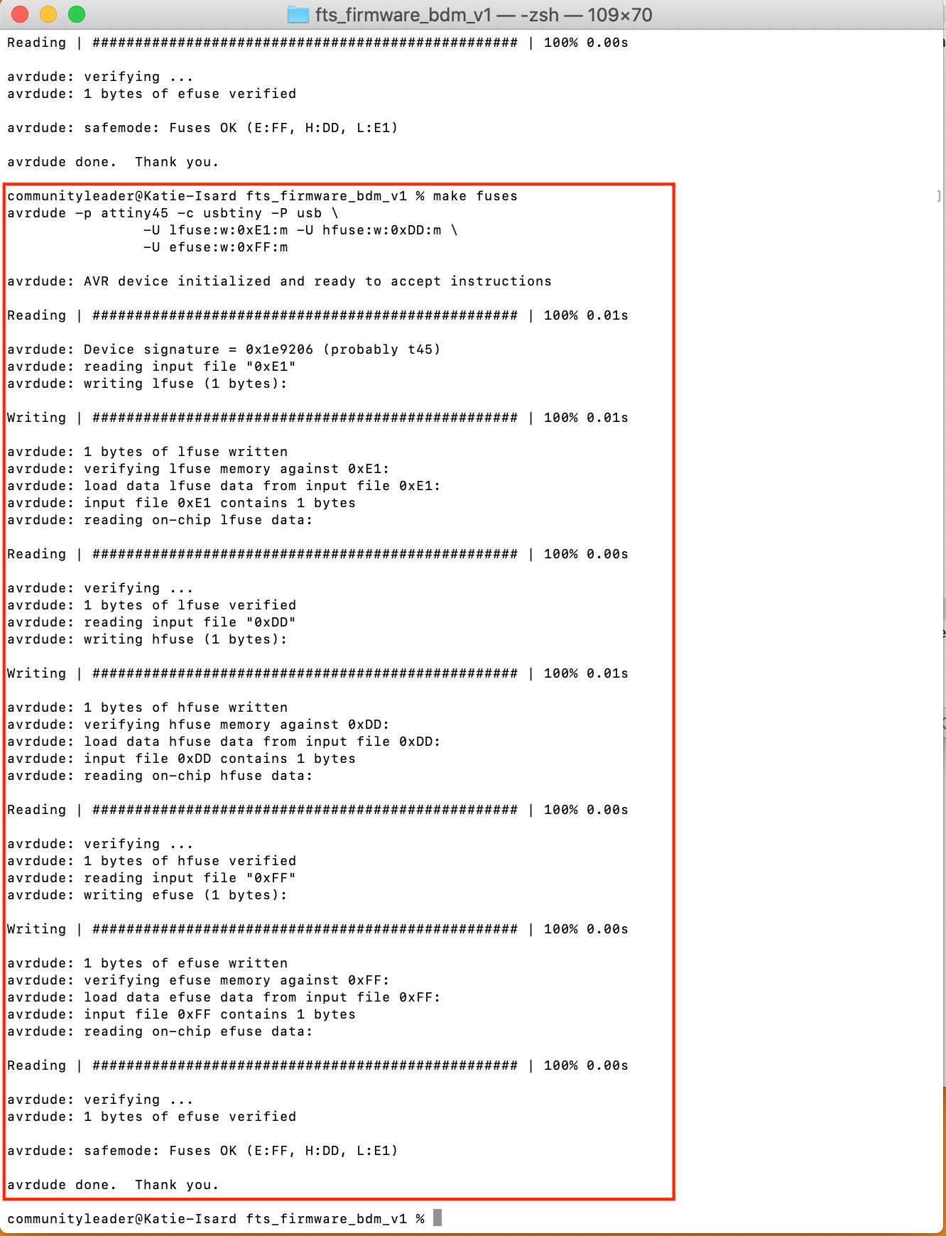
This is doing 'make fuses' this is to reset the reset pin, this will let the chip use the reset pin to program other boards, but will disable the ability for this chip to be programmed again.
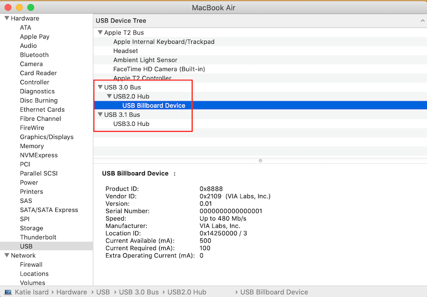
Checking to see if my USB has shown up in the USB devise tree by going to apple in the top left - click on 'about this mac' - click on 'system report...'' - then on the left side go down to 'USB devise tree' and it will show you if your USB has come up.
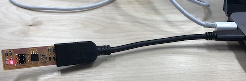
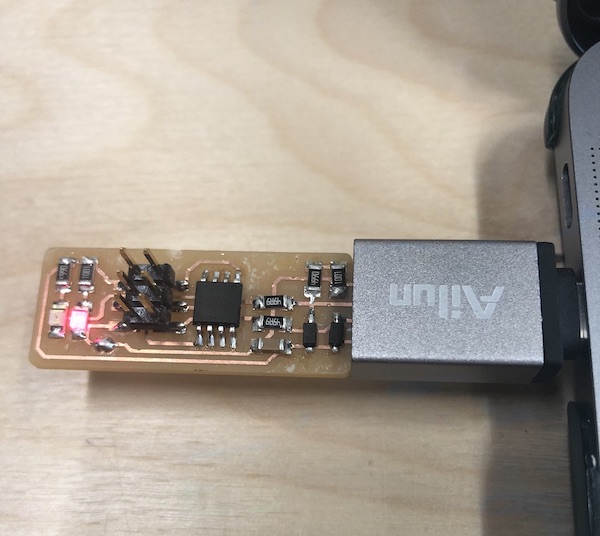
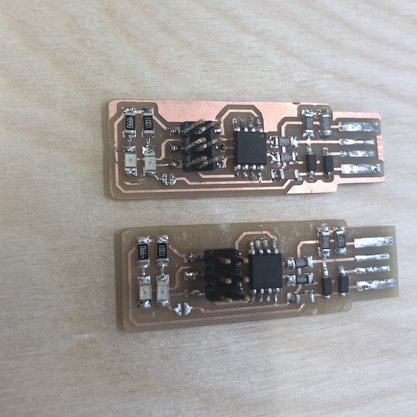
My board plugged into my laptop.
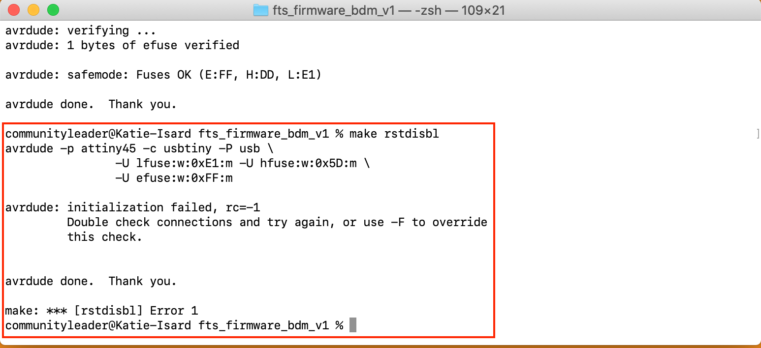
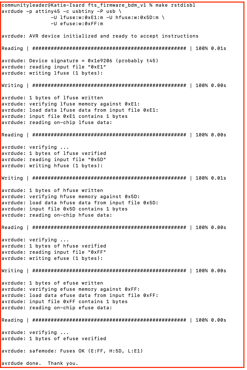
This is the point now that we stop it being a programmee and it is going to be a programmer. Doing 'make rstdisbl' this is to reset the pin in the ATting45 reset pin into a GPIO pin which stands for general purpose input output. This can be found in the data sheet of the chip.
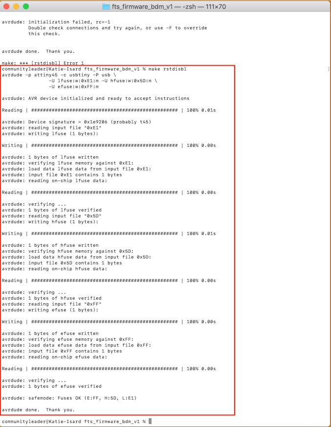
You then have to desolder the junction that you made at the beginning, I did this just by heating up the solder and then used the solder sucker to get rid of that solder which worked well.
I really enjoyed this week, I love sitting and soldering making sure that everything is correct. Being delicate and careful with the soldering for some reason reminds me of ceramics when you are cleaning your work, or painting this very delicate pot. Its a very satifing activity which I could do for a while. Getting things to wokr on the other hand I do find very hard as I don't think I know enough yet to know what to do or look out for. But over time I'm sure this will become just as enjoyable as making the board itself.