Link to Electrics Design Group Page
Hello world - when you're learning a new program the first challenge is normally to set a challenge to say hello world!
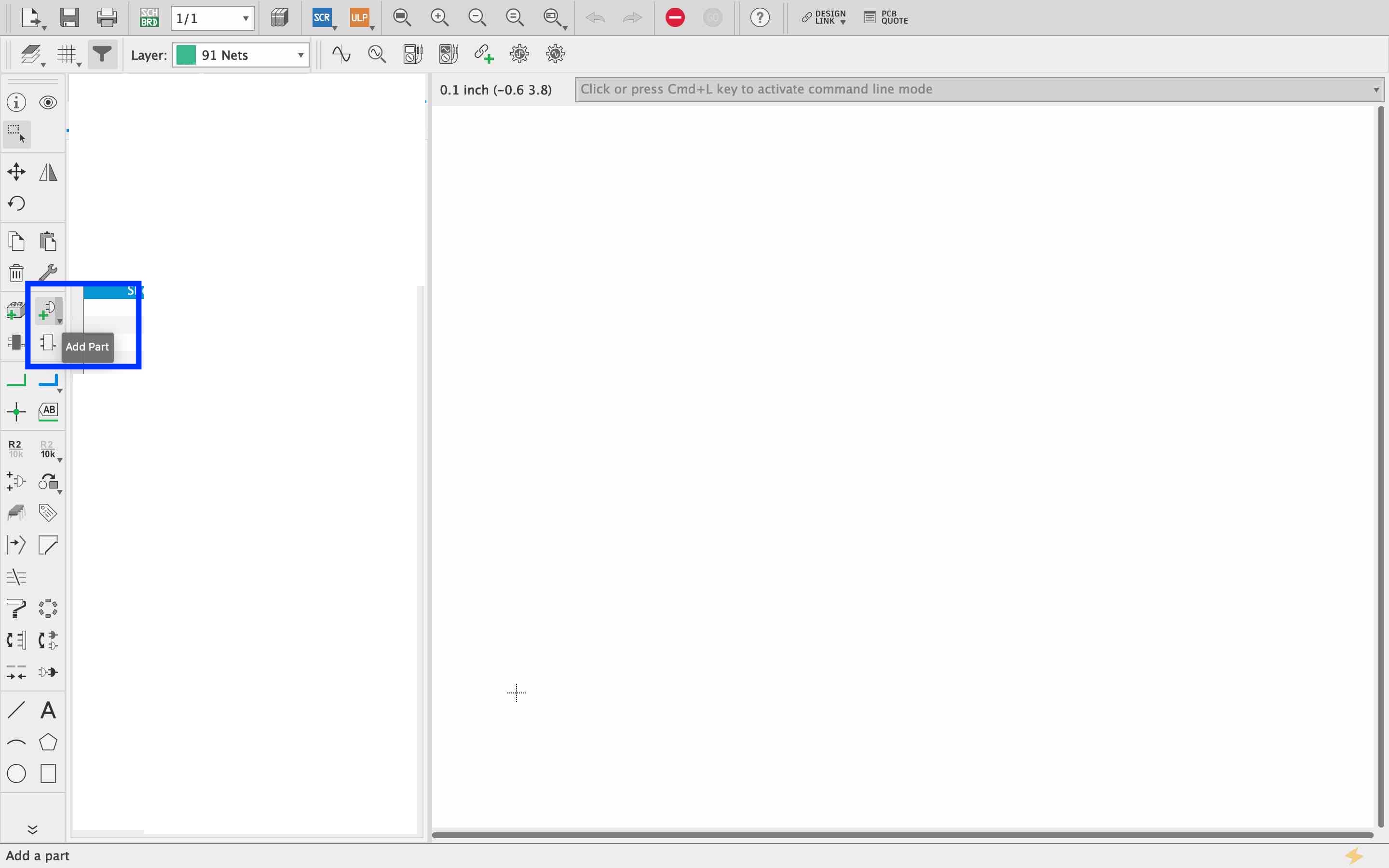
To add a component you really need to know where to look... here in the image shows you how to add those components!
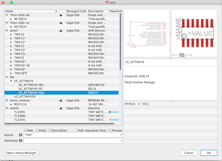
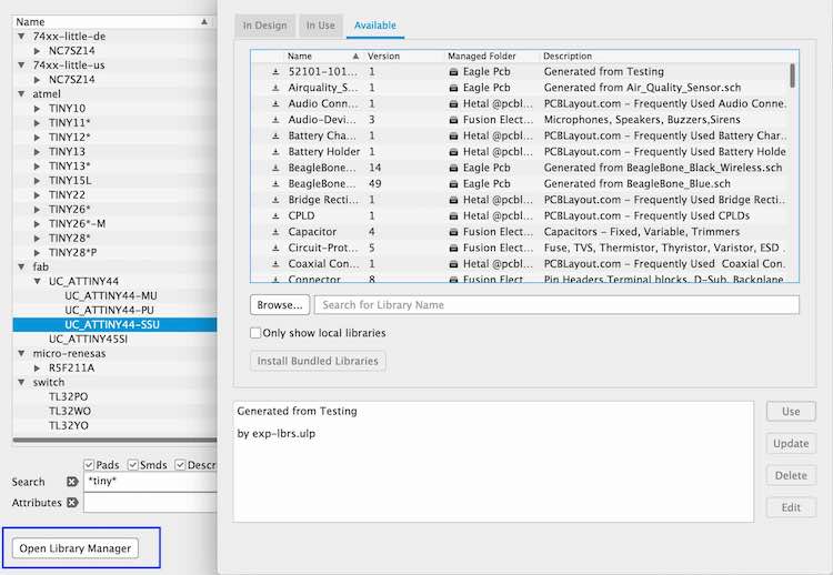
This is the library - here you can find your components you are wanting to bring into your board. Putting a component onto eagle you have to make sure you get the correct footprint so that your pads work with the component you are going to use. The pads are what the component attaches to on the board with the solder.
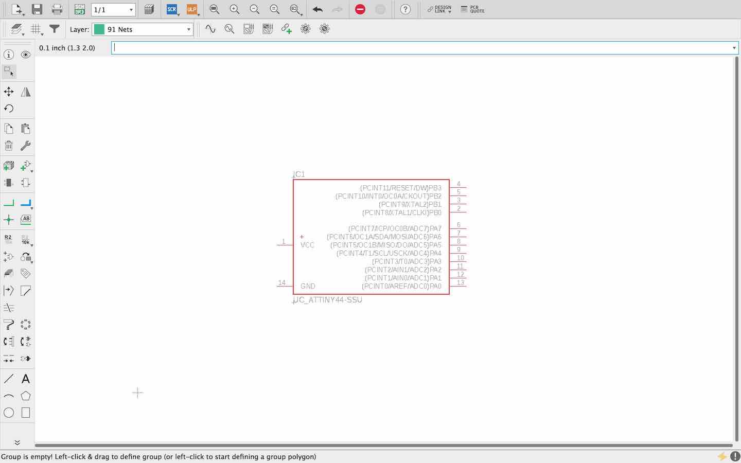
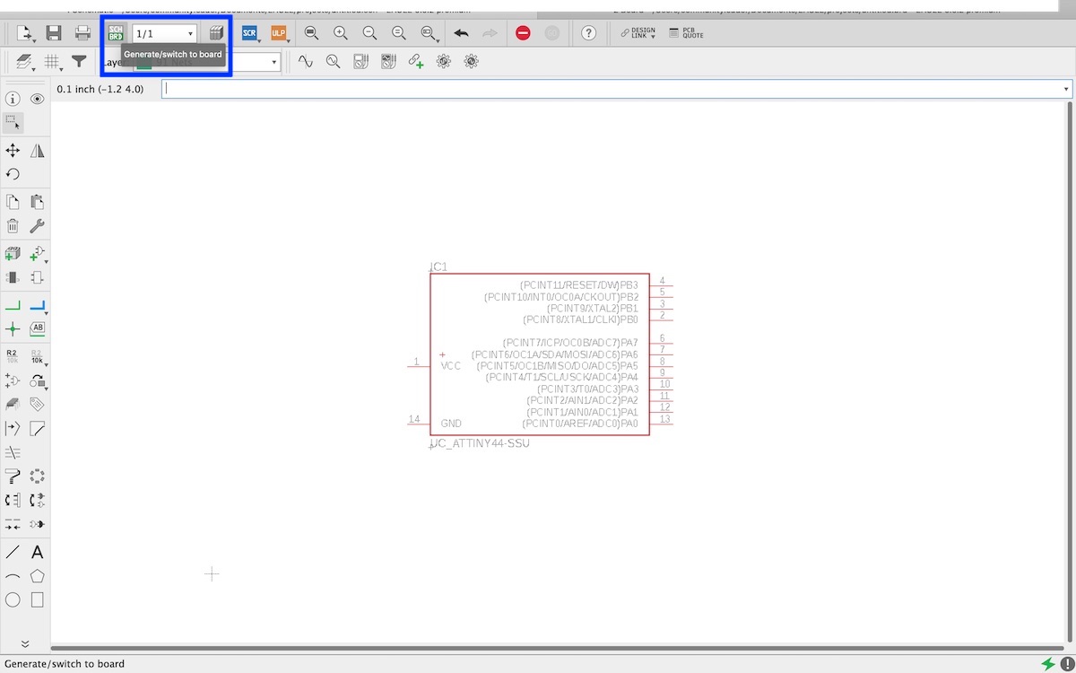
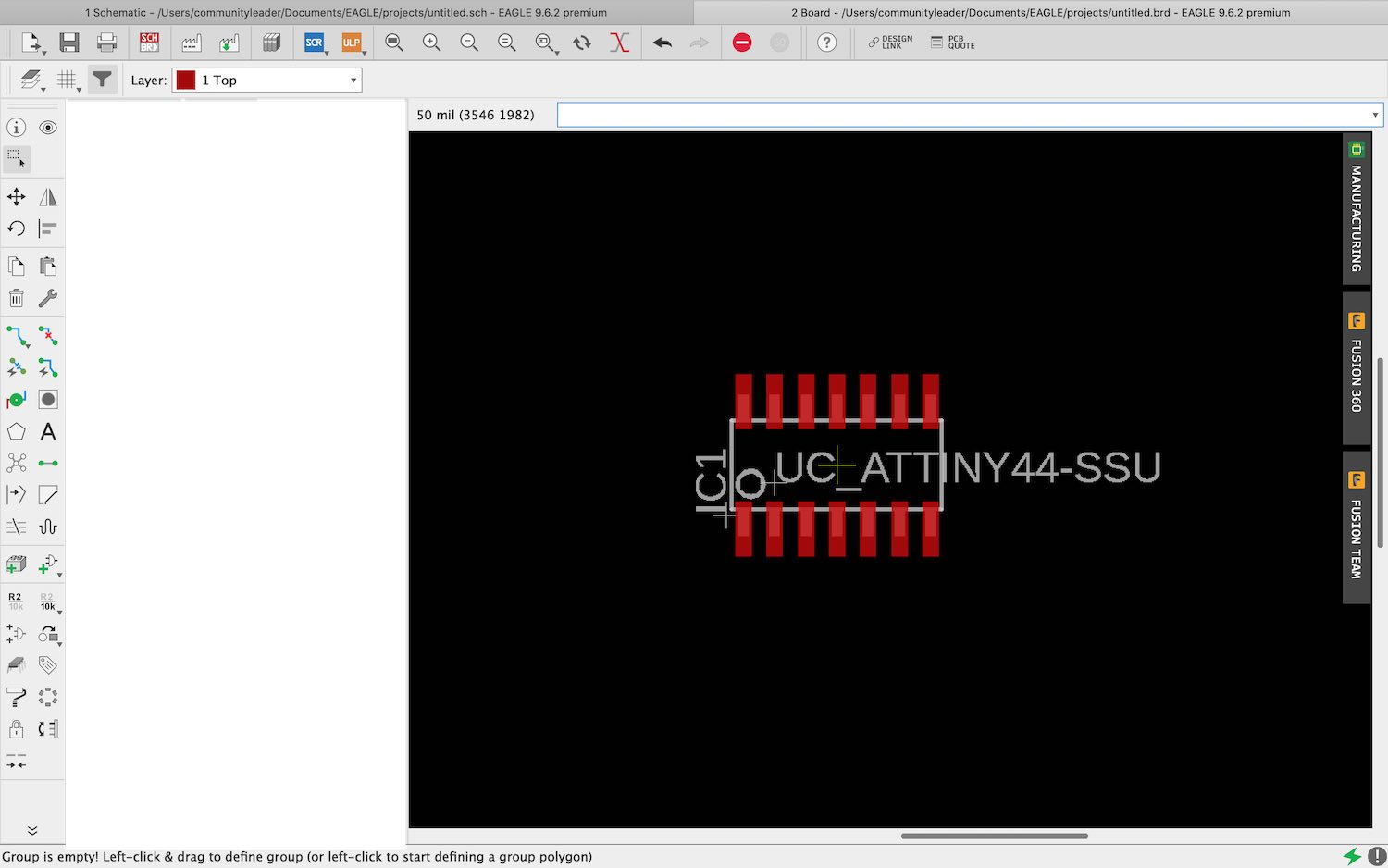
This is me adding the ATting44 chip onto my schematic in eagle, I then went to the sch/brd button at the top which then opens up the board.
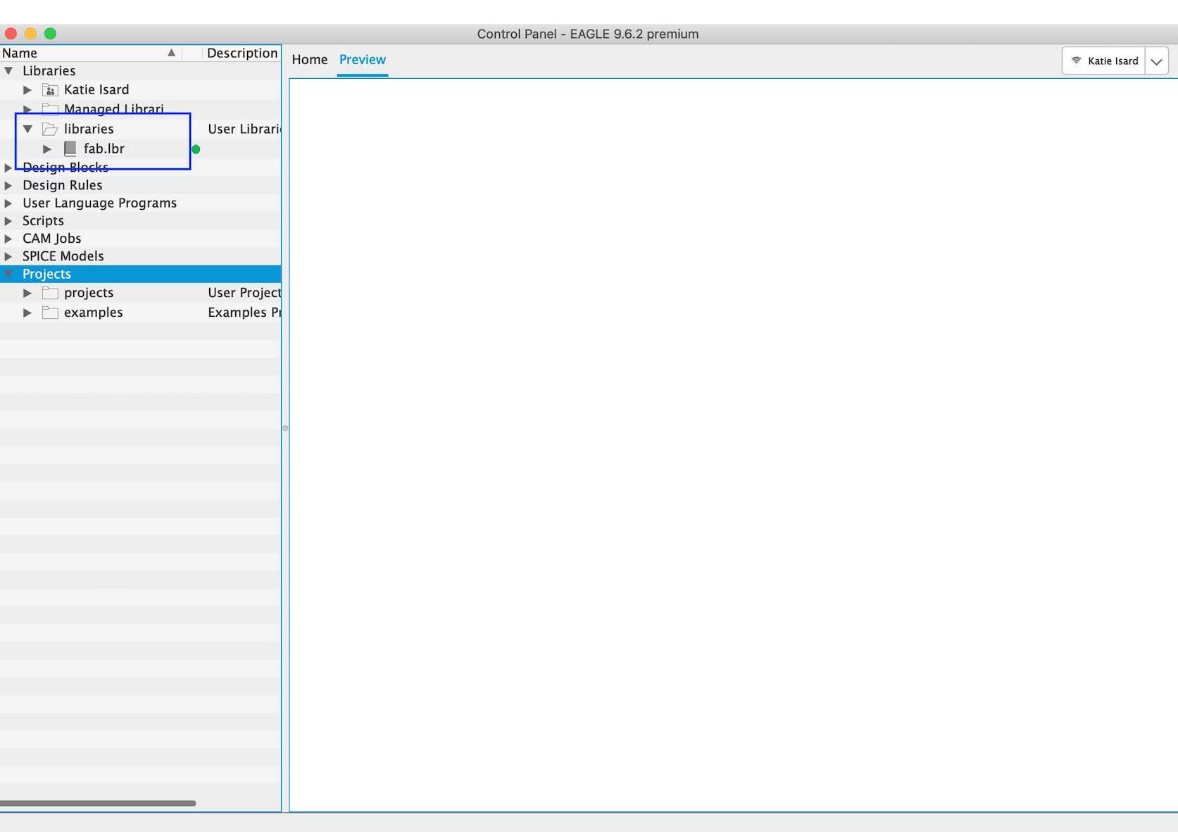
We did not have Fab Academy's library on our library so we decided to add it to our eagle as well as sparkfun as Andrew said this was a useful one he used a lot.
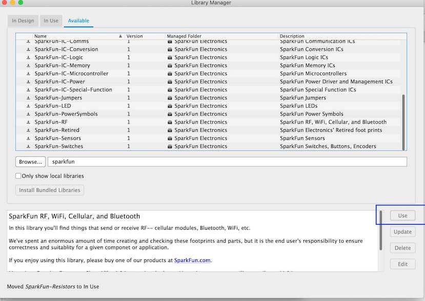
Go to open a new component onto your schematic -> press open library manager -> then search your chosen library -> click use ->
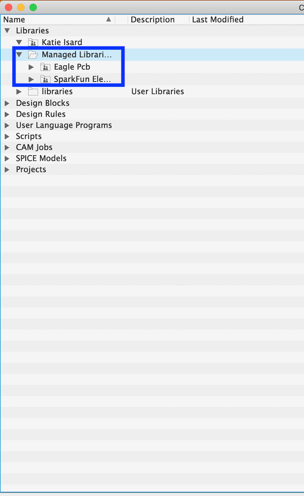
This should now turn up when you open your eagle as shown in the image below
Go to the add a component button and go through the library to find the correct resistor, it is easier to just put in *1206* as we know this is the correct size resistor we are going to be using.
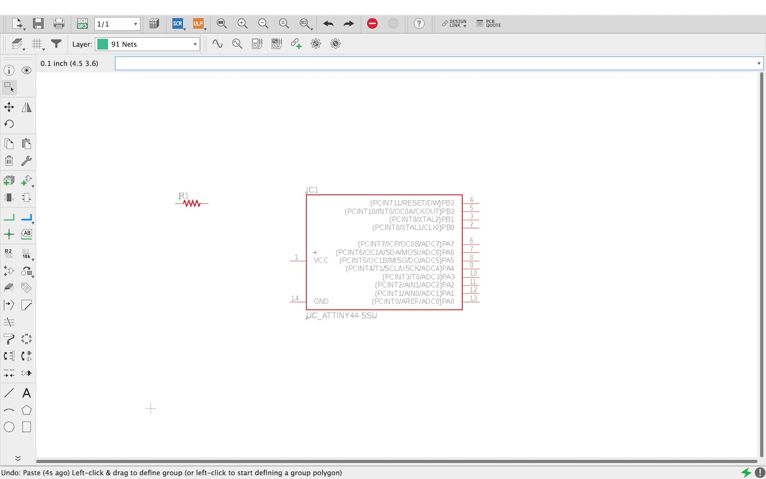
These are not traces!! These lines are the beginning of making this but we aren't going to use this!
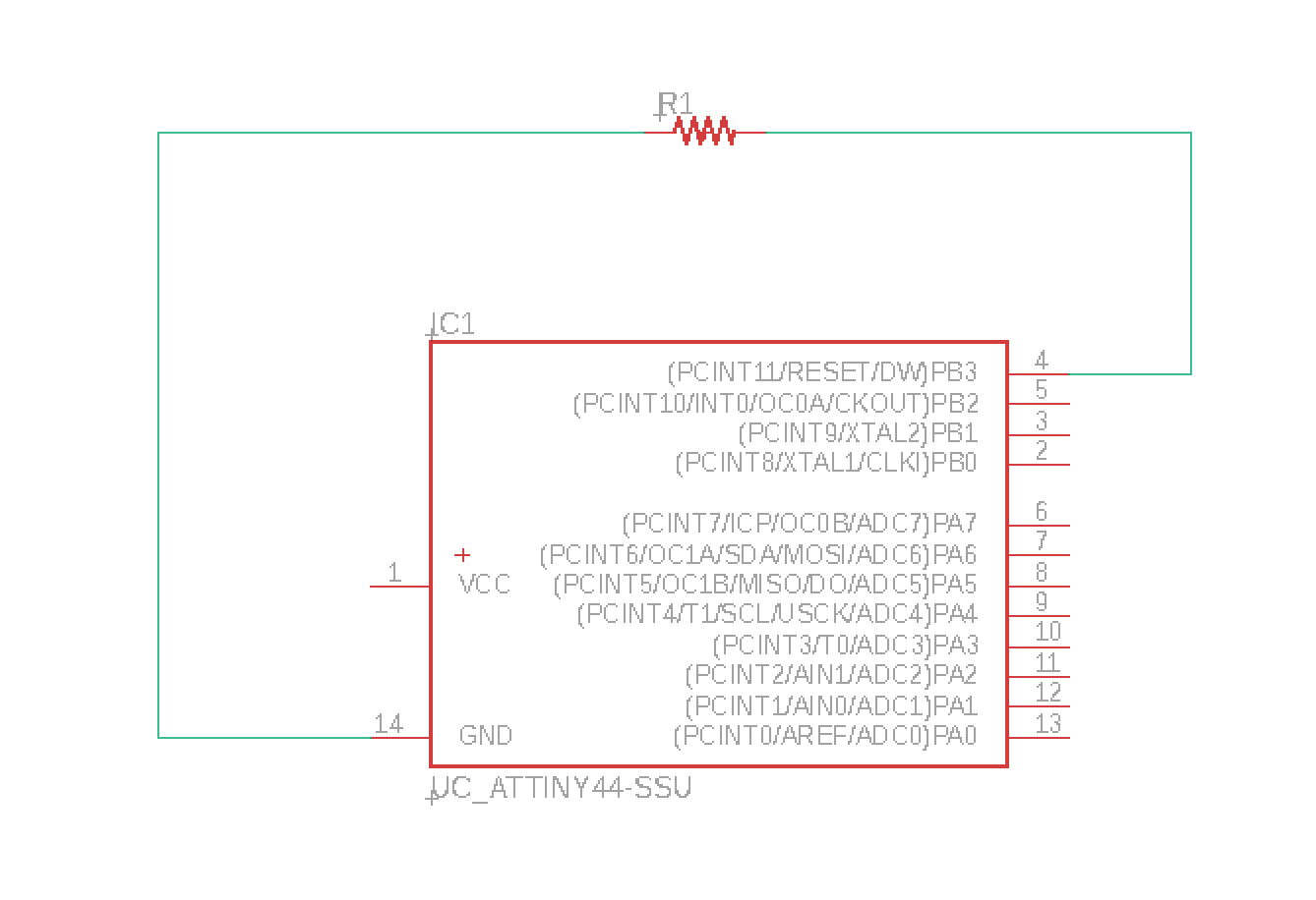
Pressing the sch/brd button to show what those green lines end up looking like when they are in the board layout rather than the schematic layout.
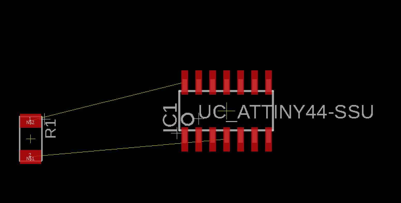
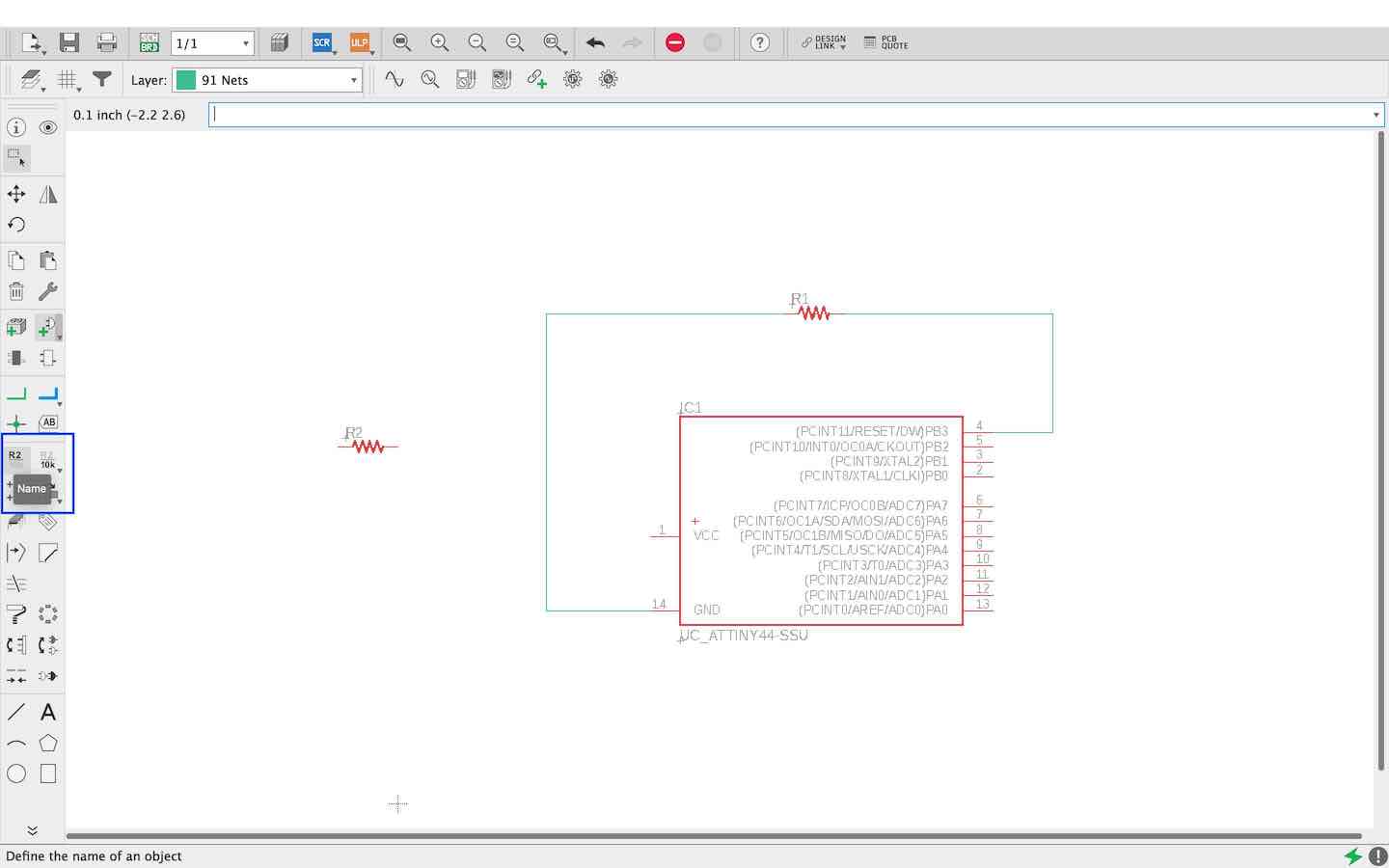
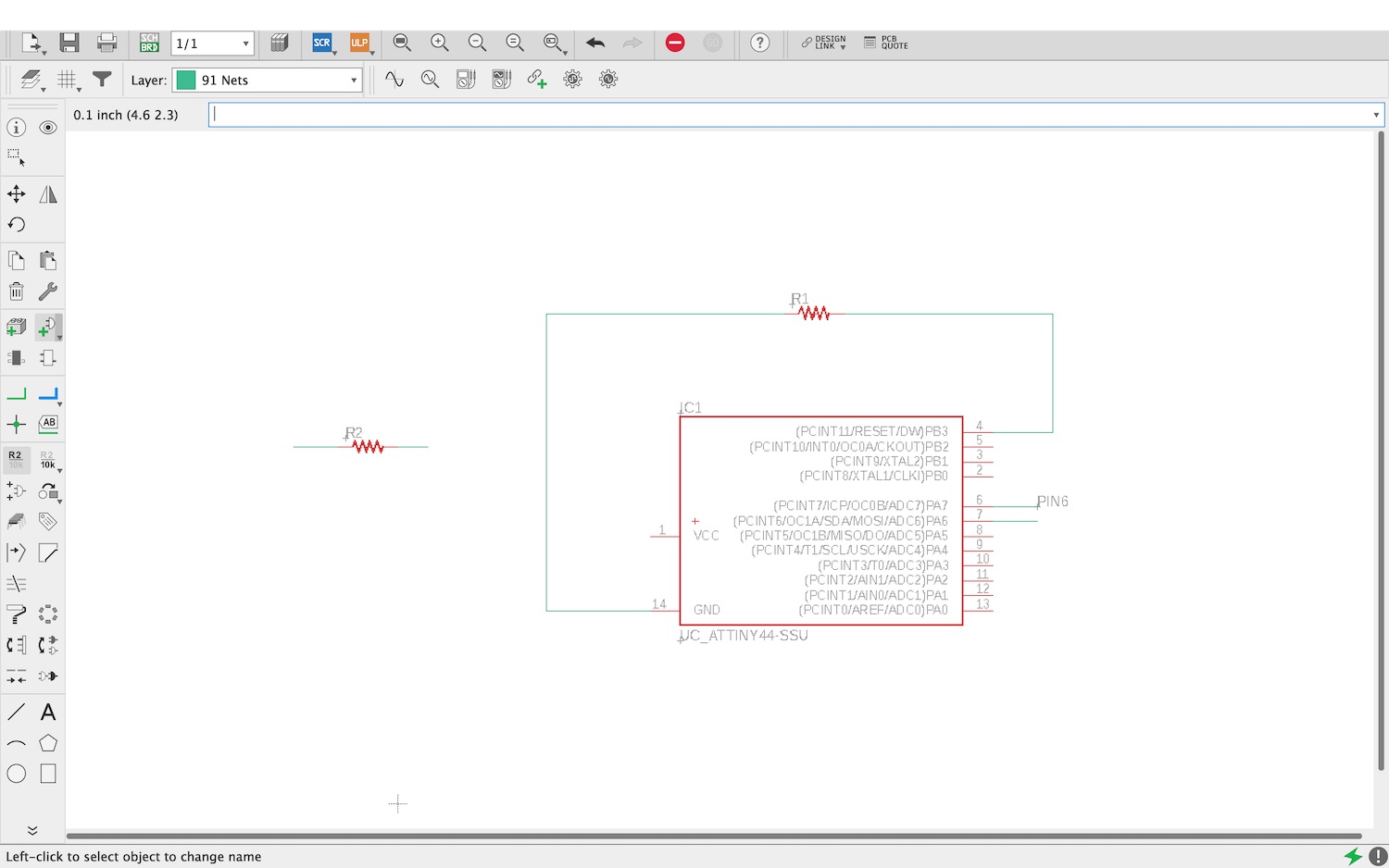
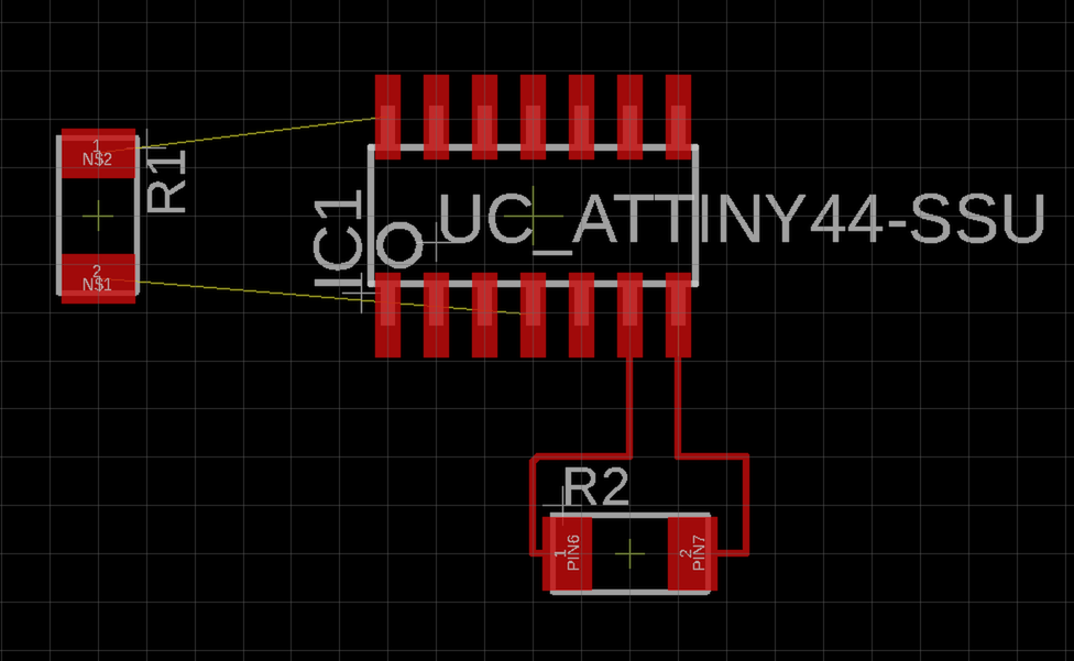
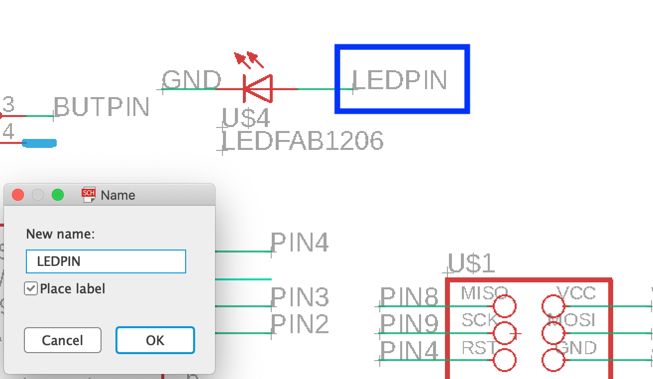
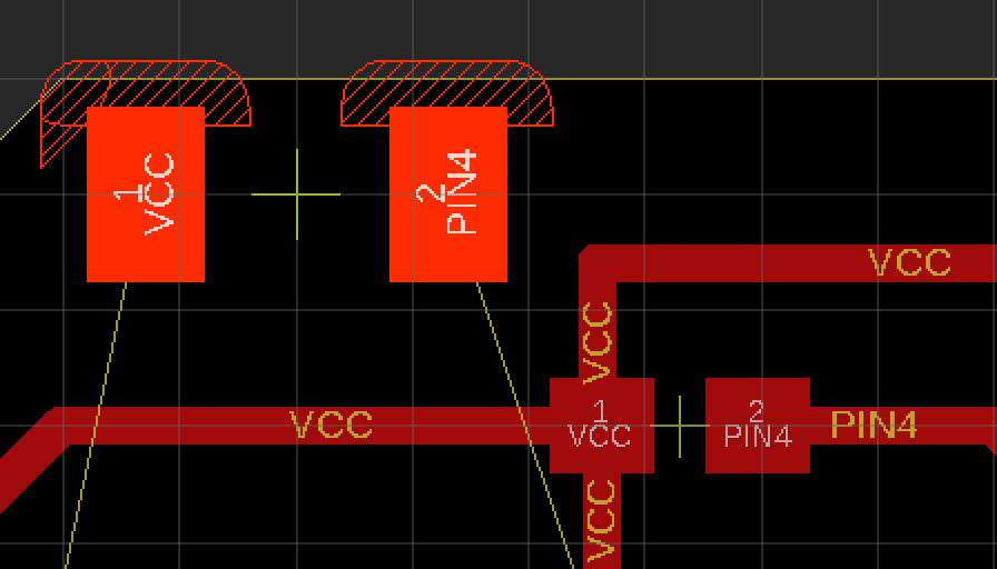
So instead of having loads of green lines going around your board as shown below you can actually just add a green line to the end of the component line. Then add the name of the line it wants to connect with.
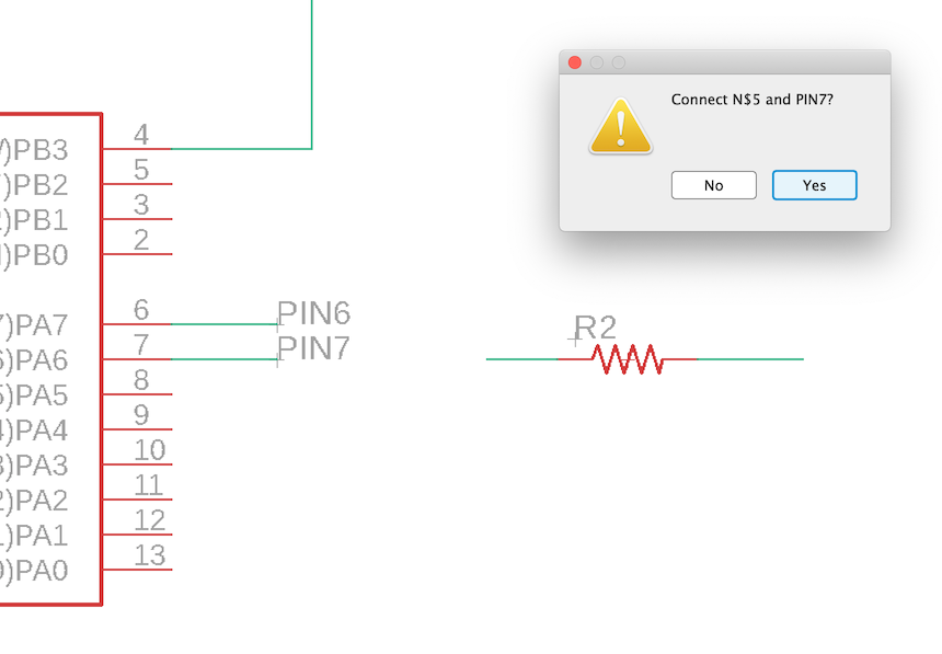
It will ask if you are sure you want to add this name to the line and you want to press 'ok' and then dont forget to attach it to the correct line so that it is named correctly. Also bare in mind this is so you can follow it later on so make it the easiest way you think your brain will understand what is happening.
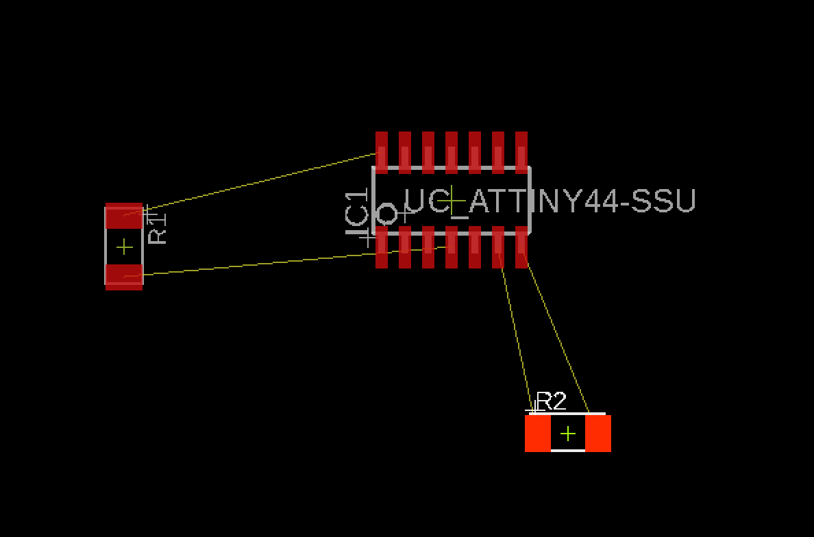
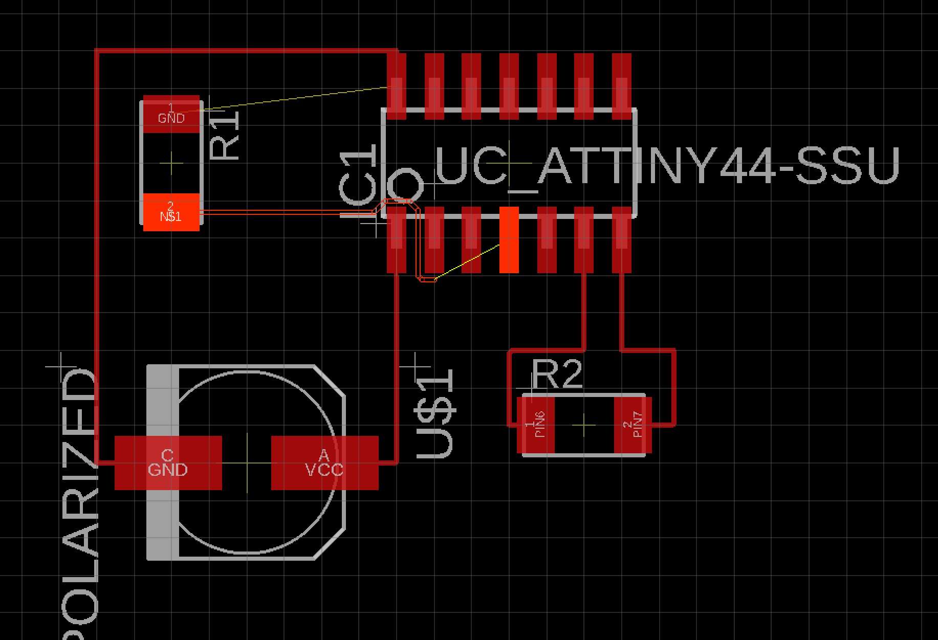
Now when you press sch/brd is comes up with the lines connected but it looks a lot easier to read in the future with less green lines everywhere!
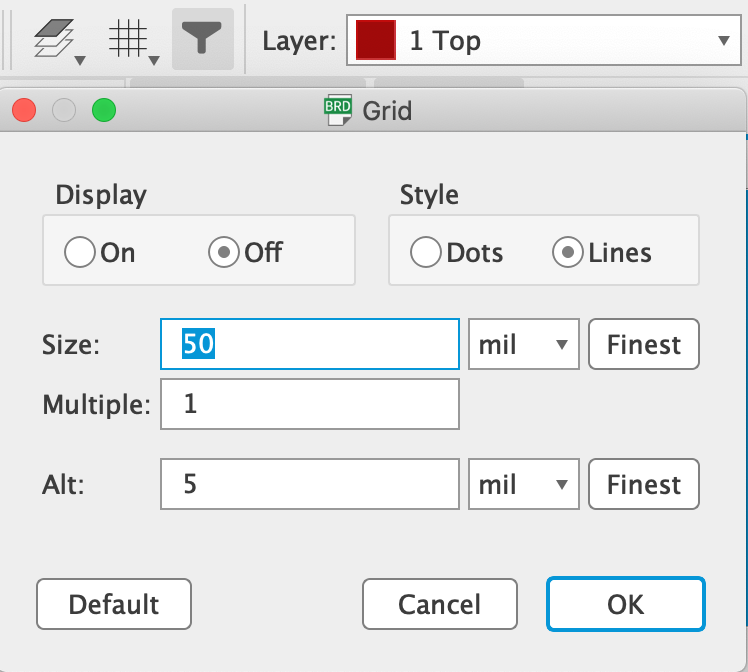
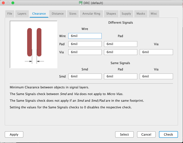
This allows you add specific rules to your board so that you aren't having to keep change it as you go. You need to be aware of 'mil' as said above this is not 'mm', I know that my milling bit is 0.4 mm so I changed all those areas that say '6mil' to '0.4 mm' - this came out fine in the final outcome. The reason to do this so that my milling bit can make it between the traces comfortably and it will also let me if this wont work.
Select the traces button as shown below...
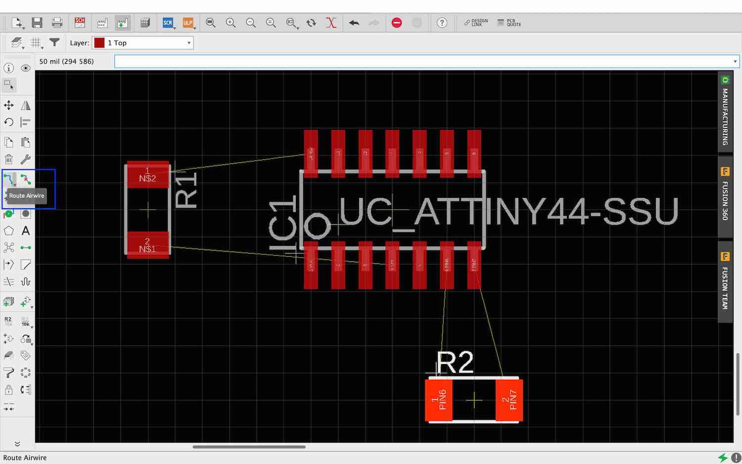
Choosing the type of trace I want to use eg 90 degree angle, curved etc - I chose to use the second from the top which gives me nice angled cornerd without being 90 degrees as shown below.
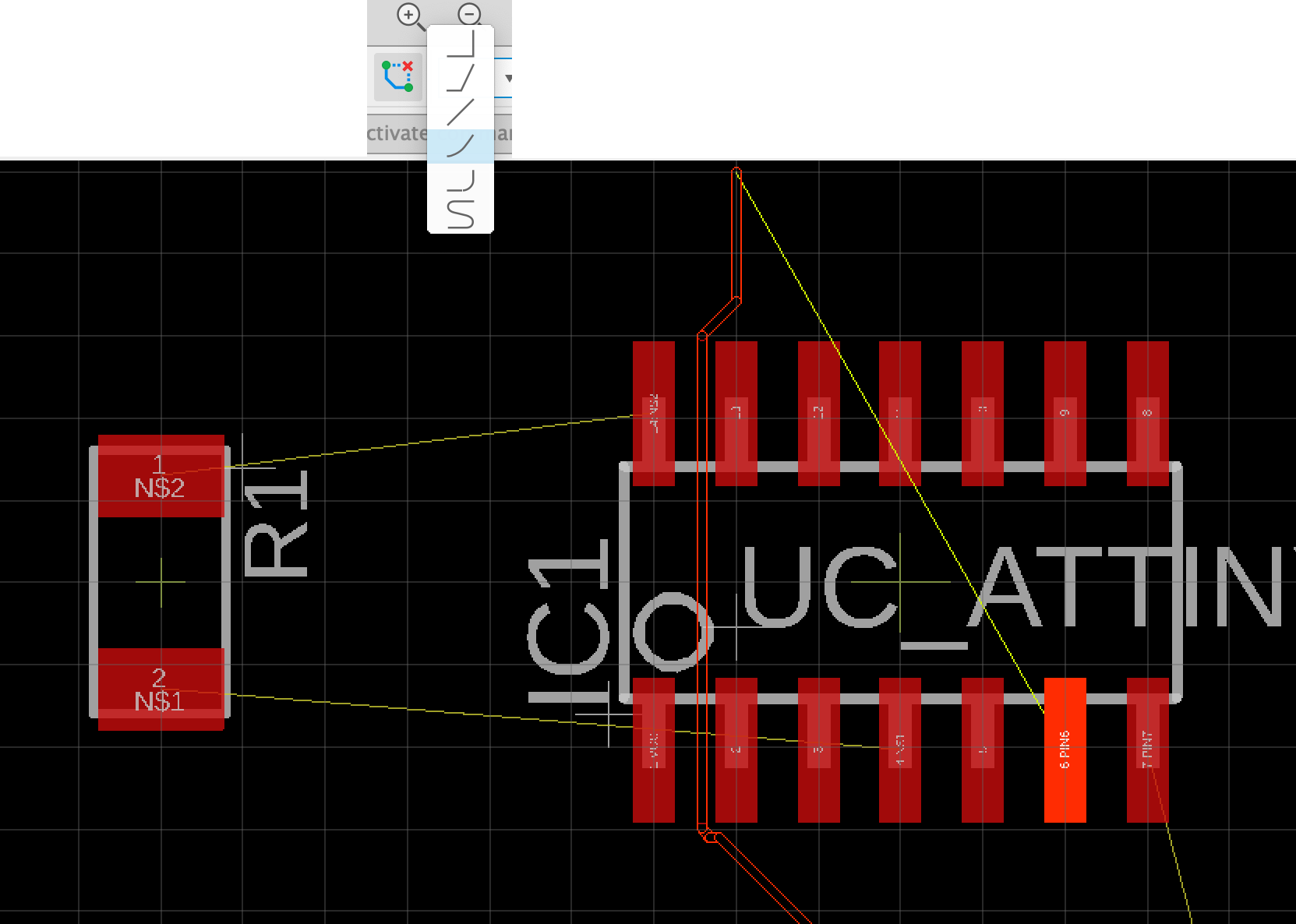
The great thing about eagle is that when you are wanting to add two pads together they light up as shown below. What is also great is that it will show you a possible route to take to get to the other pad so that you are short circuiting.
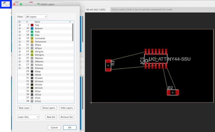
To get the layers on your board
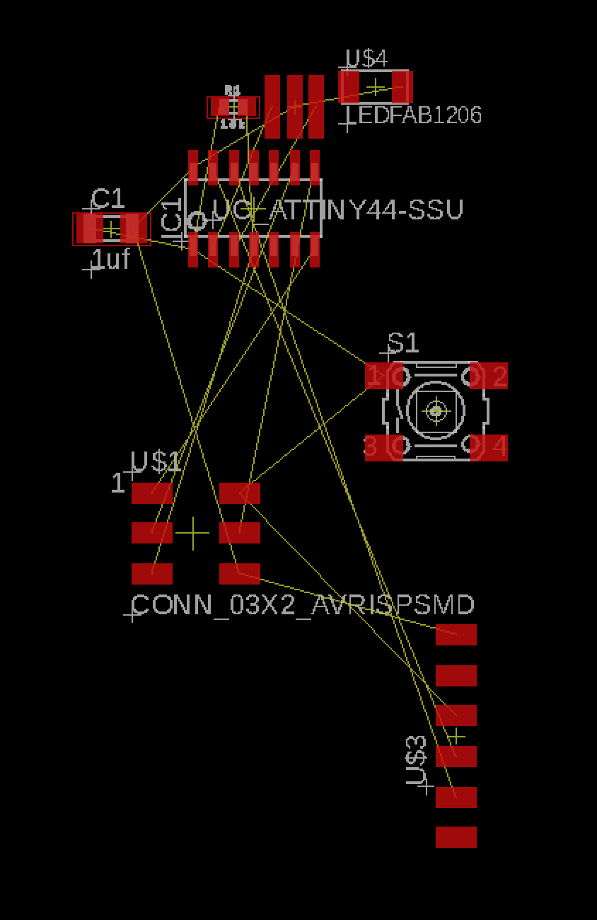
I started by trying to design my own board without looking at Neils design of his traces. To do I added all my parts onto the board without the LED or switch so that I could see what order they could be.
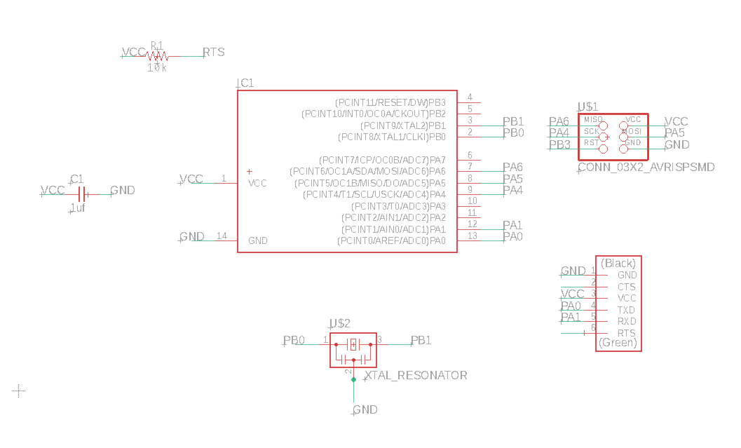
All my parts on the schematic:
I then went to the board to try and get the traces in a order that would allow them to all line up. I really stuggled with this and by the end of it I did just follow Neils as I knew it worked and didn't quite have enough pacience as I thought.
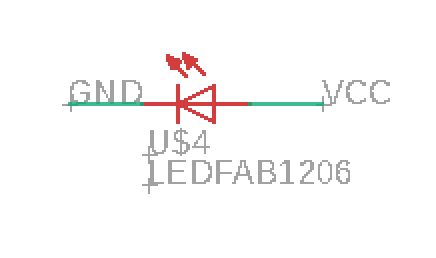
    POSITIVE to NEGATIVE
    Better to think positively before you think negatively
    Anode to Cathode
    Current flows from a to c like the alphabet
    Cathy is a negative ninny
    VCC = positive
    GND = negative
    There for the LED is running from VCC to GND
This is the point where I now have to understand the areas such as where to place my button and LED and which pin it should be connected too?
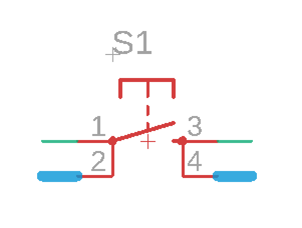
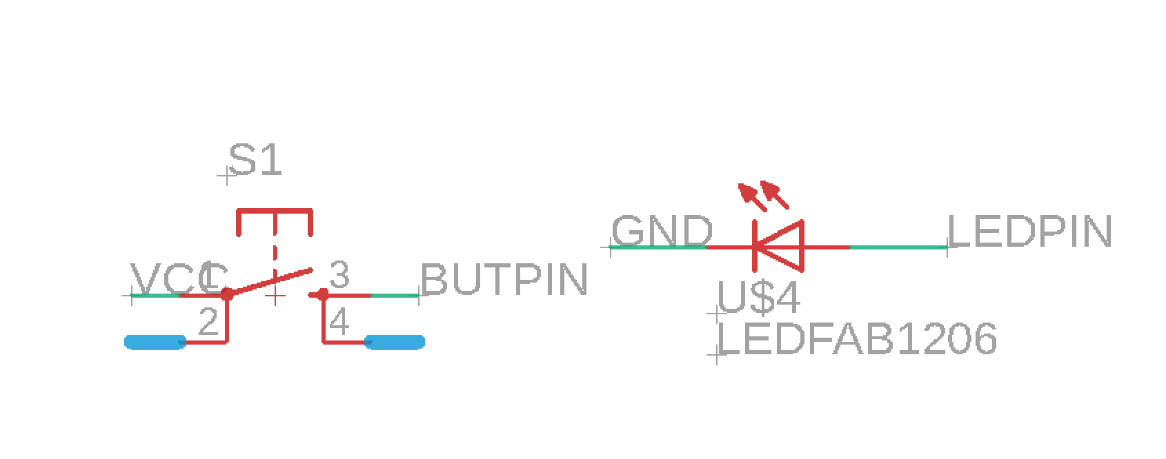
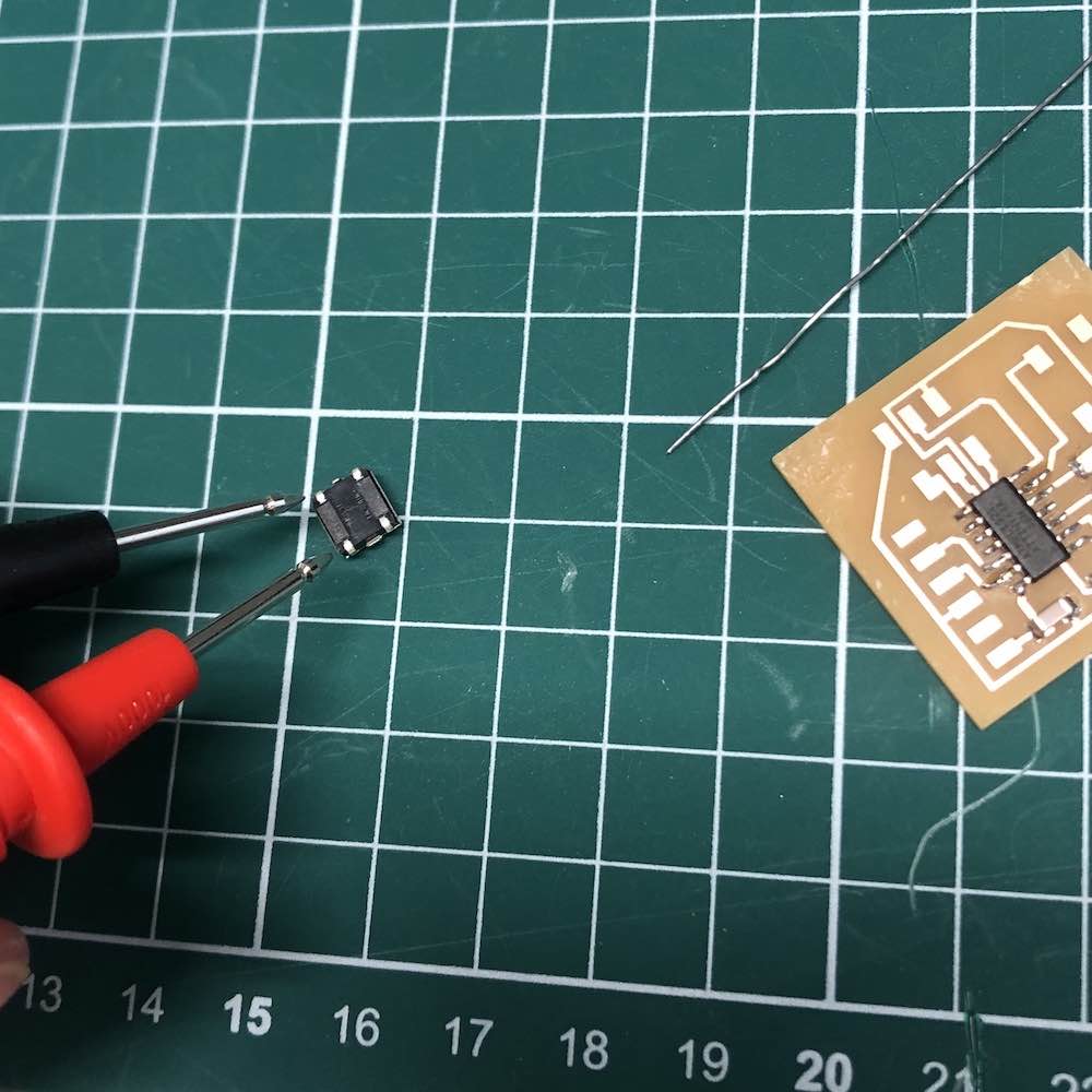
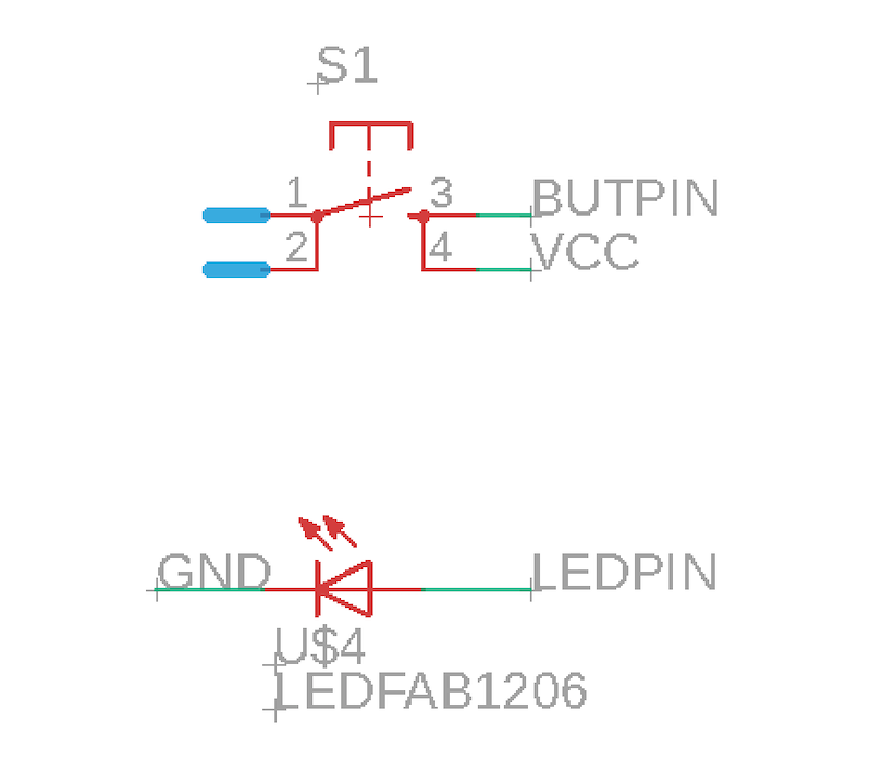
How they work - Buttons have 4 pins - two connect together and then the other two connect together. As you can see in the image there is 1 and 3 then 2 and 4 that connect. To check this on the actual button you should use a multimeter just before you solder it onto the board (I get confused about this later - just follow me now)
So to understand this in the best way I can describe... You could just attach the LED and the button together to make a close loop circuit. The issue with this is that you can not then change the output that the LED could do for example blink 30 times every time you press the button. So by passing the LED and the button through the chip (ATtiny44) you can then upload a program it later to do more exciting jobs. This also means you can add more objects to the board and scale it up if needed in the future.
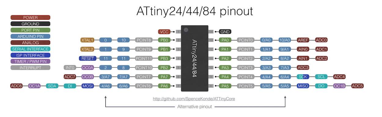
This is showing us what each pin does on our chip - for example we have different chips that allow you to do different things. I have no understanding of what they all actually mean but if I want to connect the LED and the button together I need to connect it to a pin on the chip. I need a digital pin as I know this button is digital and so is a LED, I also know I will be using Arduino later so I can check to see what pins match up correctly. I also need to check what pins are free and what the best place to put them once I have put the board together. I ended up doing this and it made it a lot easier to see what pins were free and how it will sit in my board.
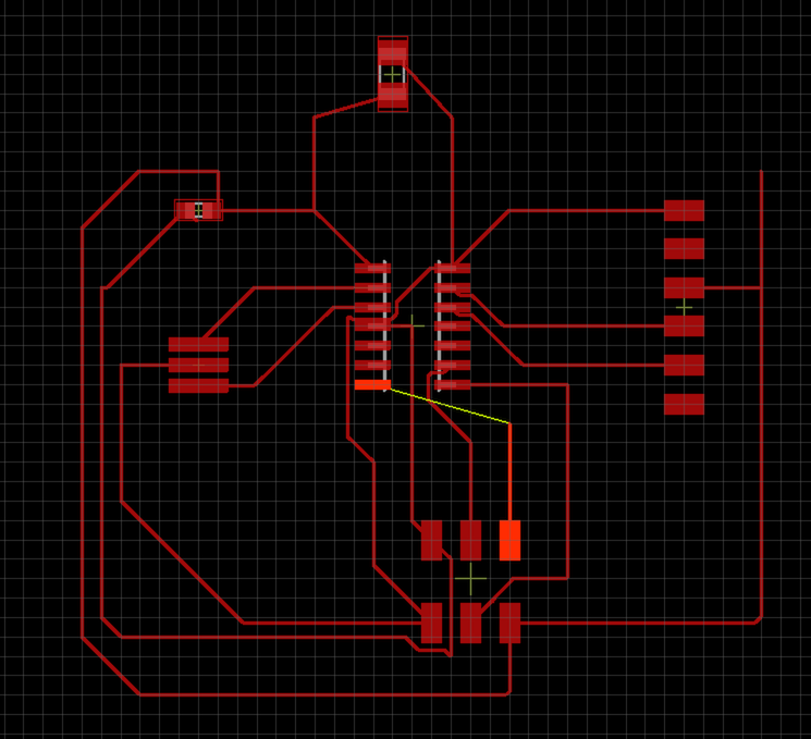
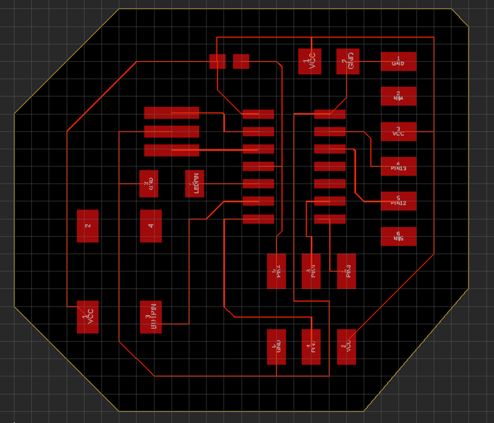
You also have Arduino, digital, analogue, GND, VCC, Selecting 'board' to see what my board looks like and... its a mess so time to tidy it up and attach the traces
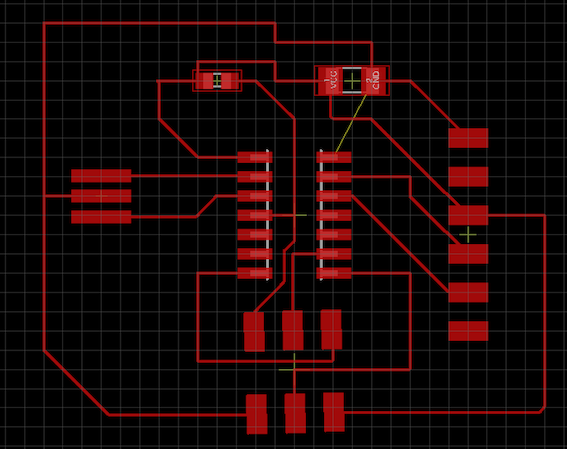
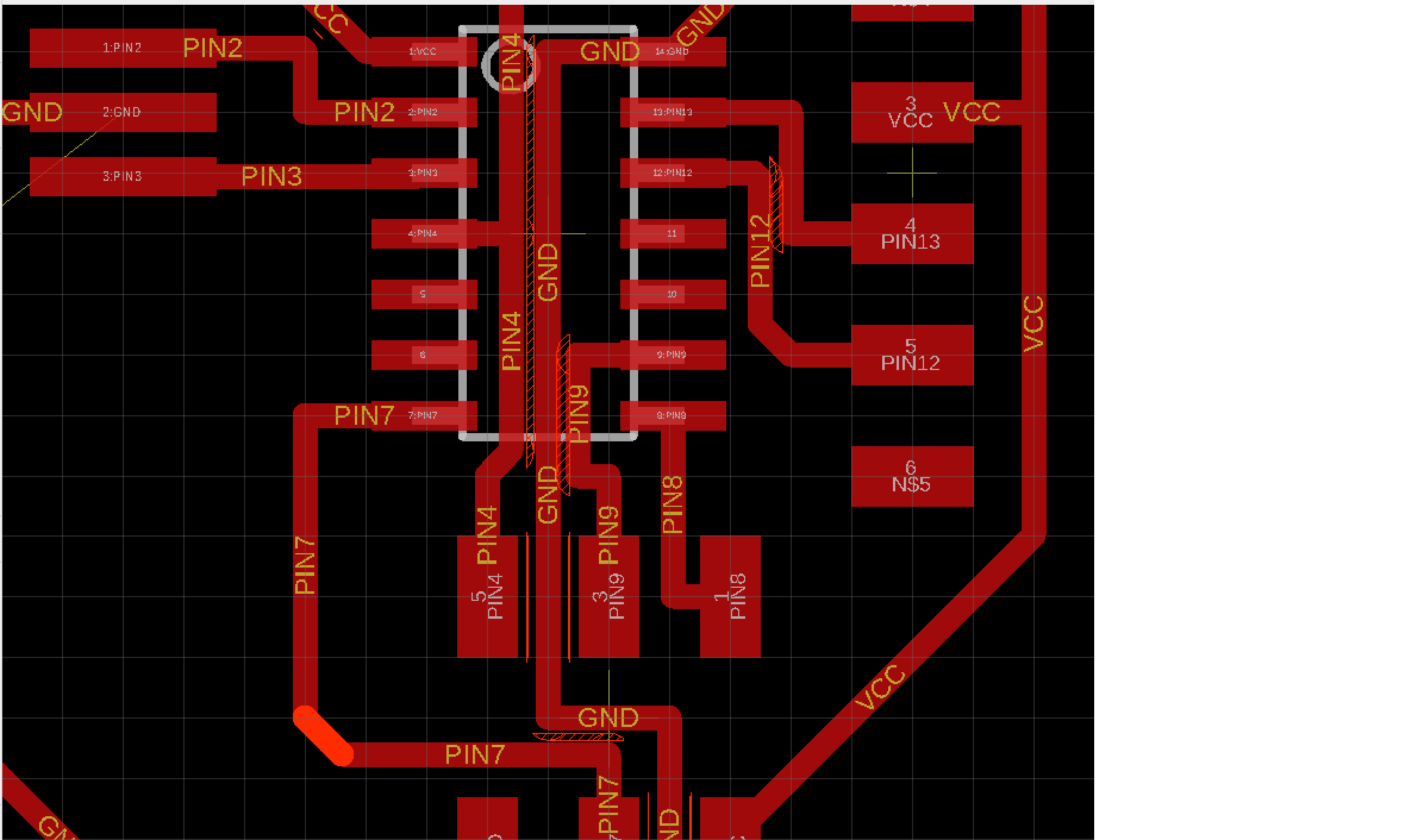
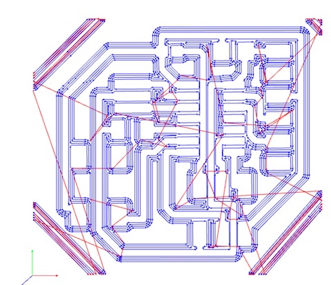
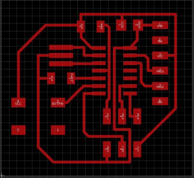
I actually start by putting all my parts on the board without thinking about the LED or button. Then to see which pins are free I start by placing Neils board together the way that he did as previously all the other variations I was getting stuck with. Seeing which pins were free I then renamed then 'LEDPIN' or 'BUTPIN' which then gave me the yellow lines to line up with my components.
Added all my traces and then Andrew said my lines are too thin so...
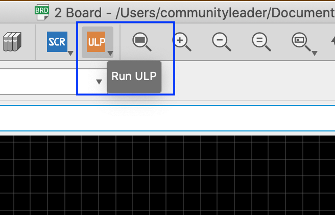
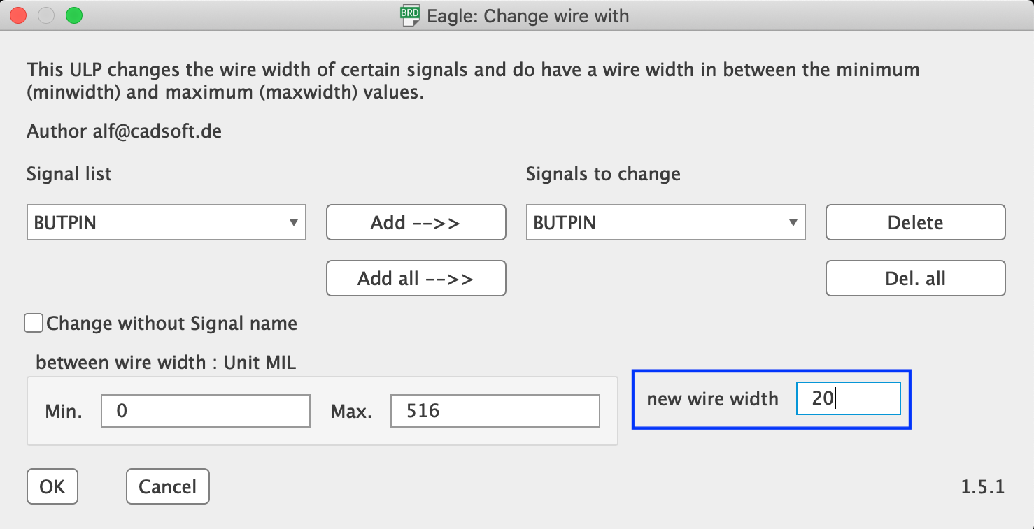
Go to ULP at the top of the page
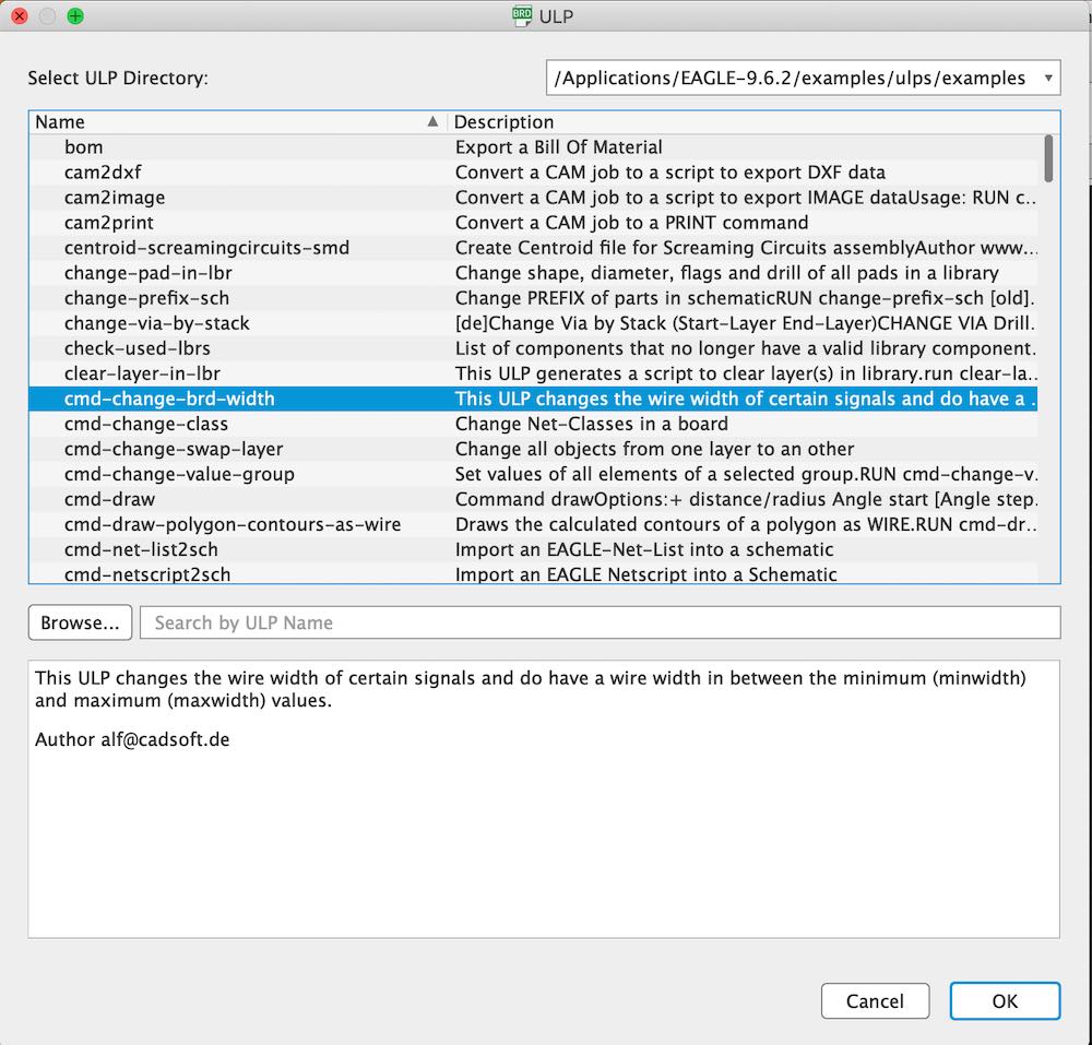
Go to 'cmd-change-brd-width'
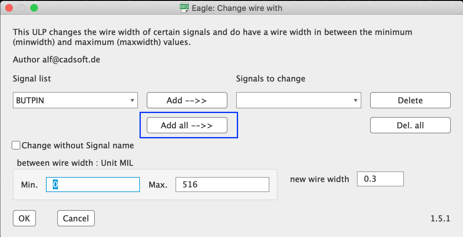
'Add all' this is adding all of your tracers to be changed, so this means that if you needed one to be thinner you can make it so just that one is.
Now to do 'new wire width' and it is measured in MIL which is 1000mil = 25.4 mm so I chose 20 MIL.
This was too thick as I had placed in restrictions in place so that my 0.4 mm milling bit can fit through the gaps between the pads and traces. I changed it to be 16 MIL so that this milling bit can fit through.
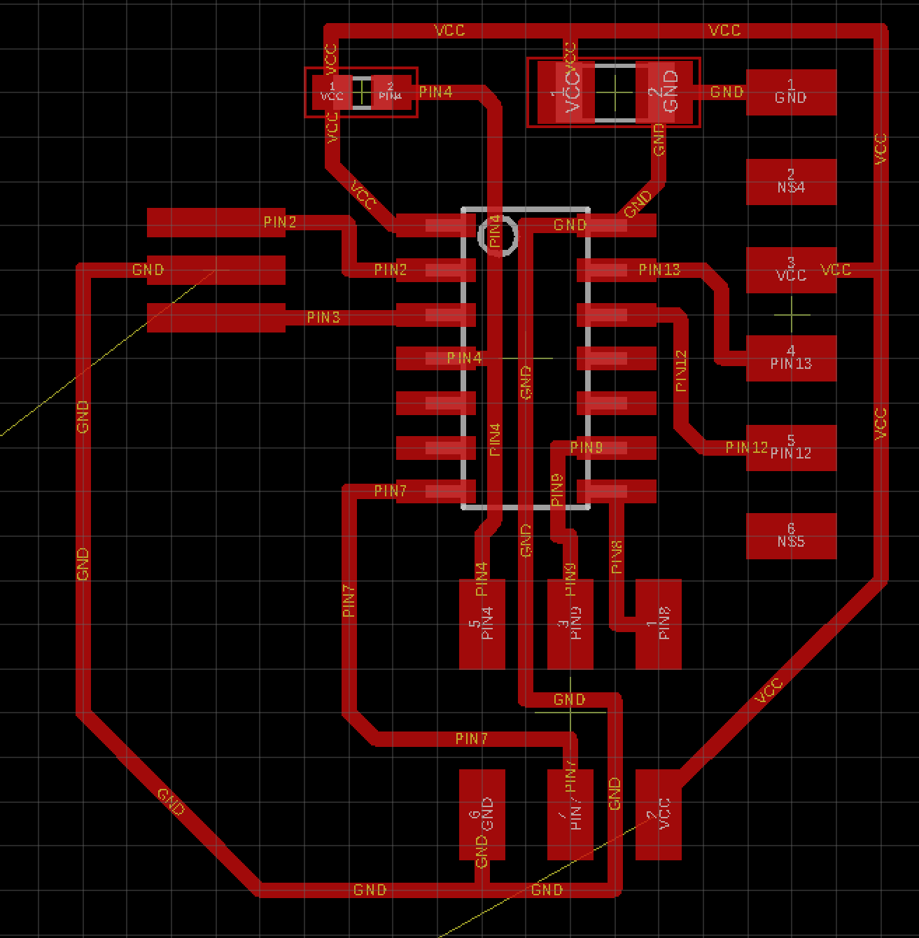
This worked much better and I still had to move some traces around so that the red marks didn't come up.
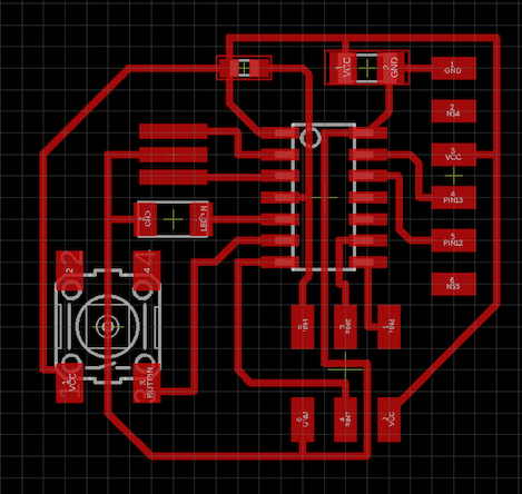
Me adding the button and LED (I know I forgot the resistor - thats coming up) Andrew showed me that I can place the button over a trace as this can straddle the trace and not course a short circute.
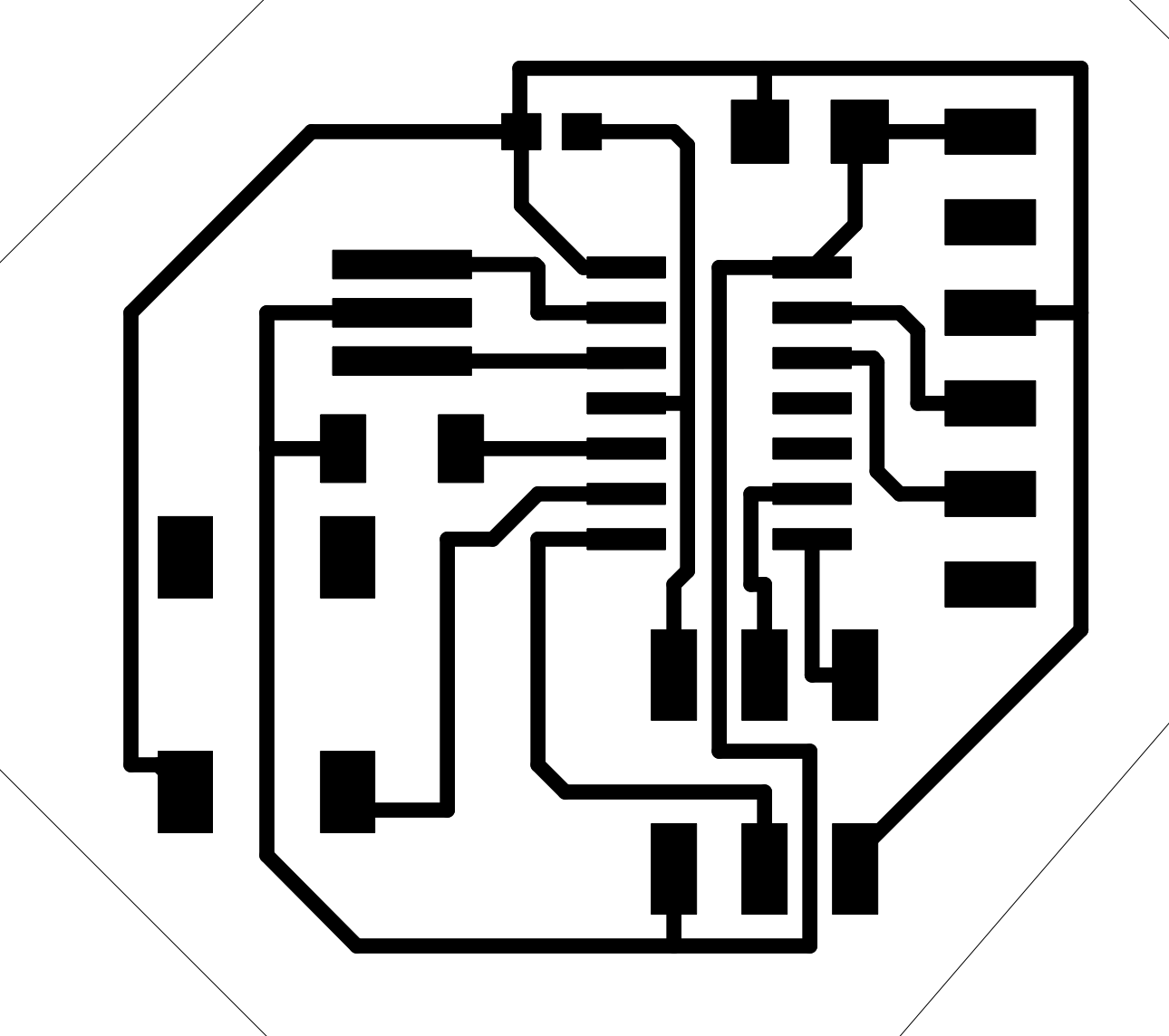
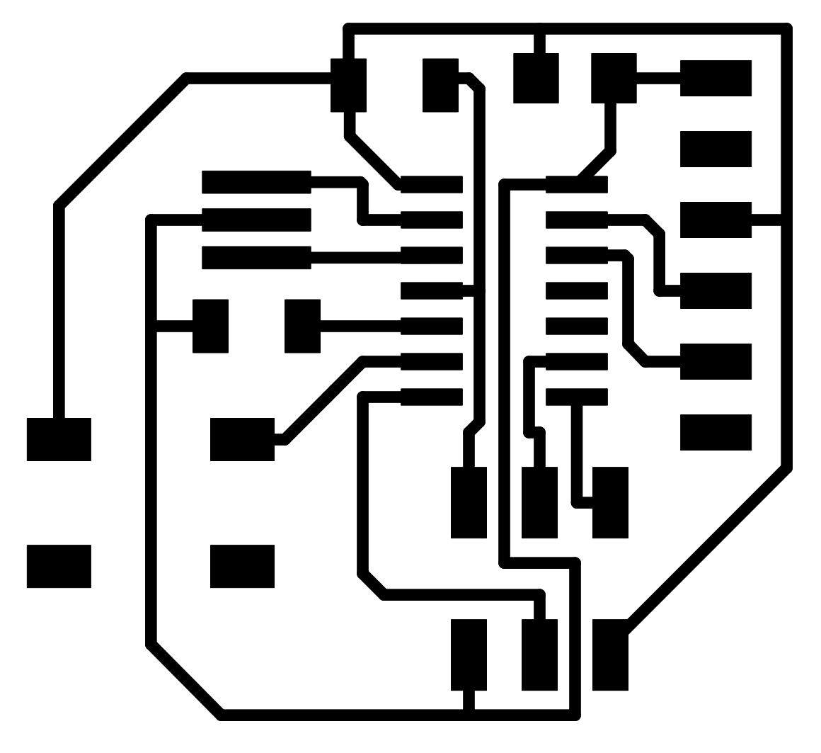
This is me exporting it as a png and it comes out double the size it should... so instead
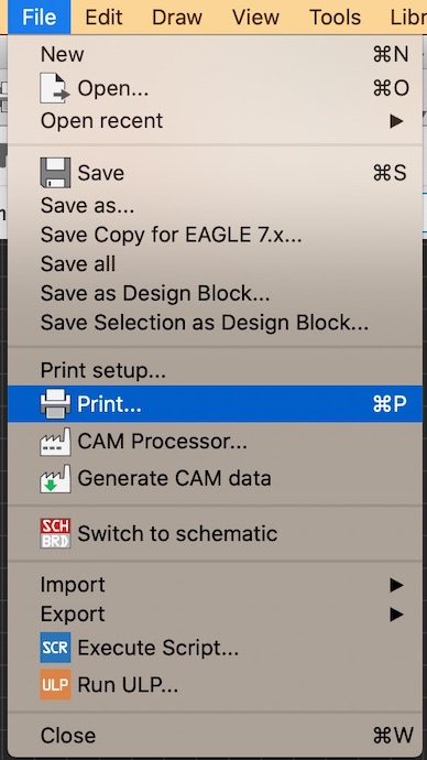
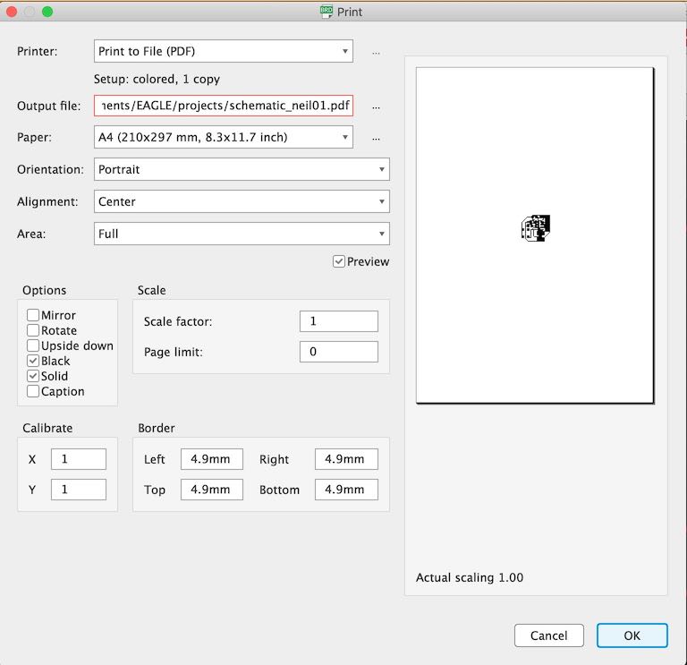
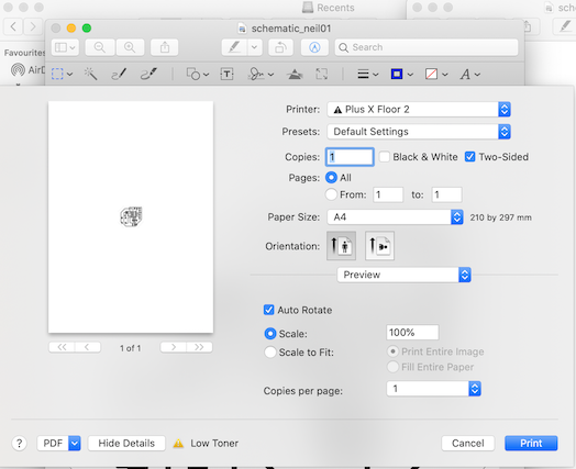
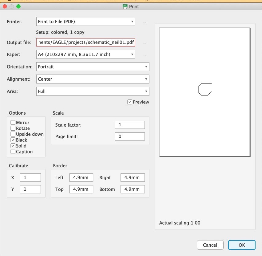
I then go into file --> print (not print setup)
This is so that my page comes out the correct size otherwise it come out HUGE as seen above.
When I first printed the traces on just a piece of paper I noticed that when placing all the components on the pads the resistor pads where too small for my resistor.
So I went back into the schematic and downloaded a new components for the resistor.
Placing my parts on my board to see if they are the correct size, from placing them on the resistor is incrust as the footprint pads are too small for our resistor.
This new register as it was bigger I had to make a few changes to my file so that it would work with the constraints I had in place.
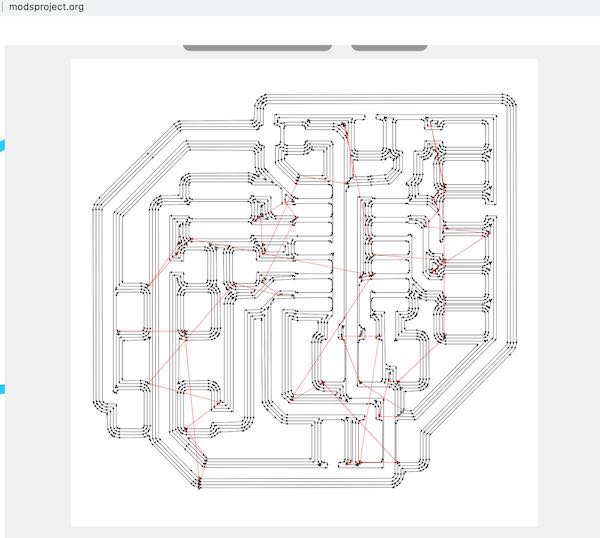
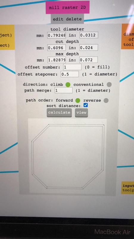
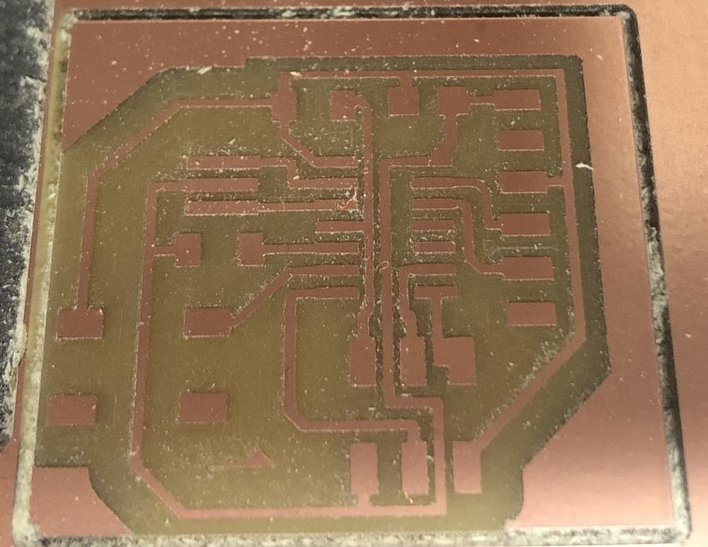
I then went into mods and started making my board, this is when I realised I hadn't gotten rid of my lines around the board so had to go back on myself and redo the printing the PDF.
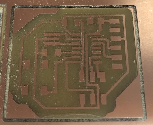
This is the first stage of it in mods and I am rather pleased with the outcome!
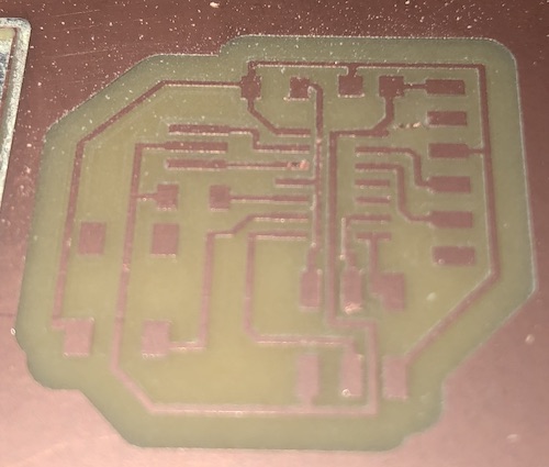
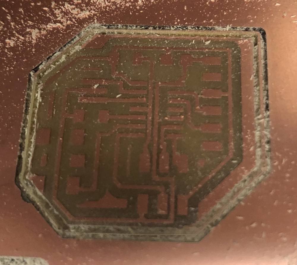
The traces have been cut out correctly but when i cut it out there was something wrong with my outline.
It still came out nice and smooth another than it cut off the button pad so I need to check and find out why it cut two passes
When printing for some reason the right hand side wasn't coming up on the screen?
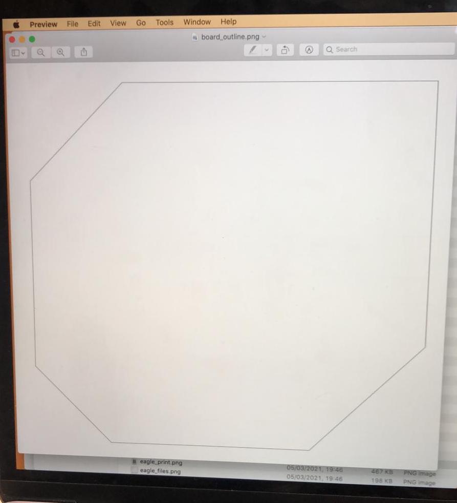
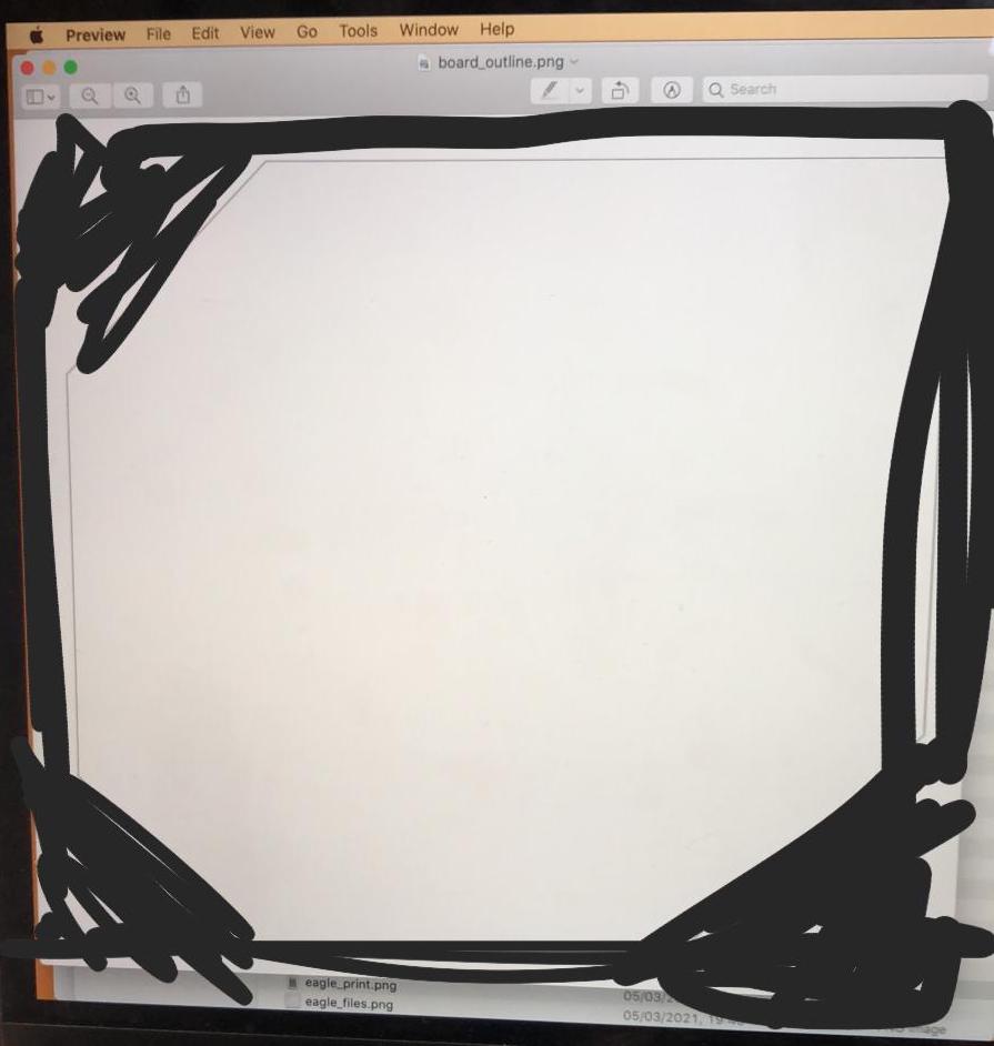
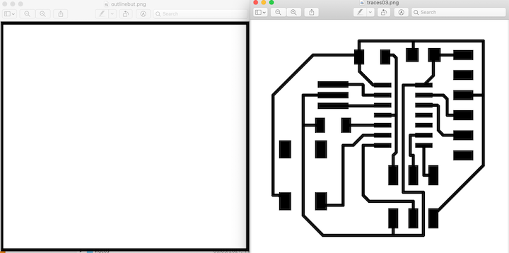
Exporting outline in print eagle but as you can see the outline is not coming out complete. I then tried to print it and the edge wasn't there, so I decided to draw the outline of my board in preview which worked fine.
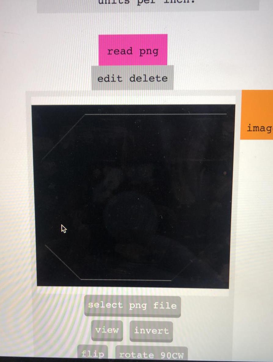
I just should have checked my old notes from week 4 and noticed I had the file wrong, you need to make sure it is black around the edge and then white where you traces would be going. What happened was that because there are two lines here it followed those two lines and there for cut out my board twice.
As you can see the png was fine I just hadn't made the file correct, the outside should be completely black. I sent it to Andrew and colours around the edges to show me how it should look, obviously I should have followed my instructions from week 4 so silly Katie.
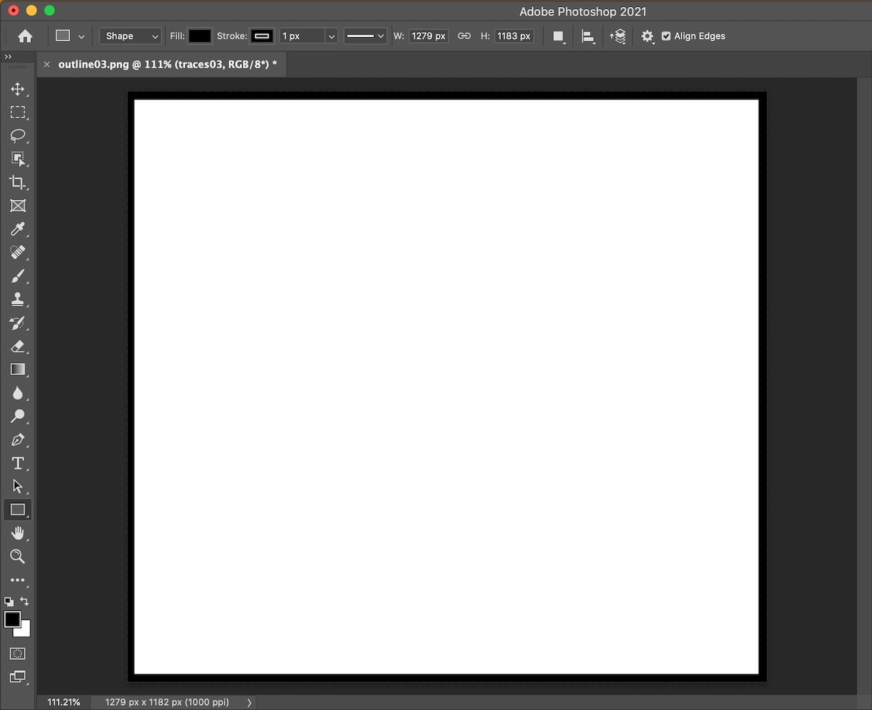
In photoshop I changed the outline of the board so that it was black all the way around the outline so there is now extra line.
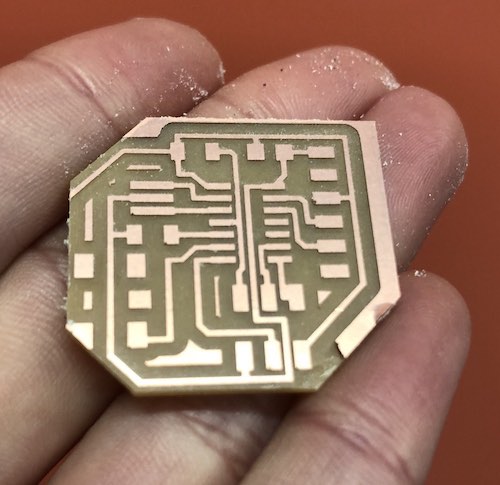
So I cut a new board which the correct outline and traces, making the board square was a lot easier to make the outline black when in photoshop or preview.
This is kinda where I had done it correct but then because I wasn't sure what I was doing and now realise I wasn't sure how buttons actually worked I thought I had placed my button pads the wrong way around.
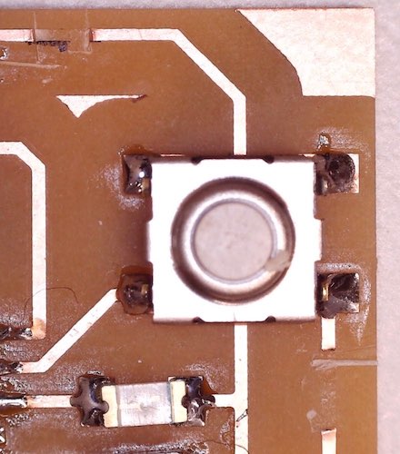
So in my head the button as we know has 4 pins but only two of them match up to each other eg 1 and 3 or 2 and 4. When I placed it on the board I thought the pins should both be on the traces, I now know this is incorrect and the point is that you press the button and you create that connection. So I checked the button to see which pads lined up:
It also made no sense to me as the button pads didn't line up correctly... but they actually did I was just confused.
So I went back into eagle, redesigned my board
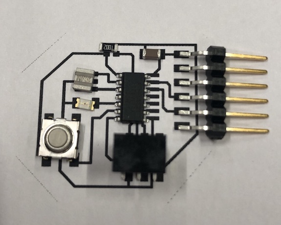
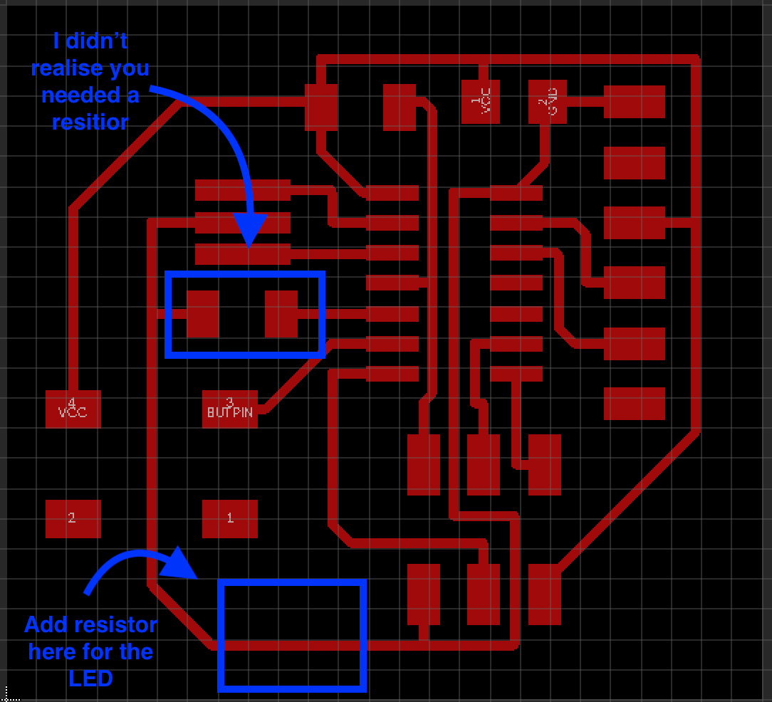
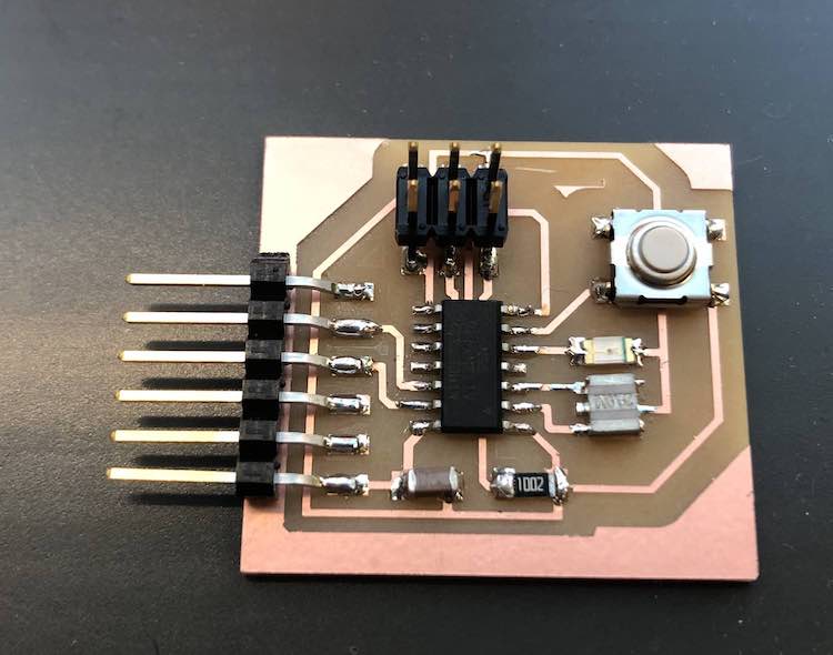
The board came out lovely! (Even tho the button is on the wrong way around... ) You also may have noticed I don't have a resistor... that is because I didn't add one, don't worry I remembered but only because Andrew pointed this out.
Button was the correct way around before I have now moved it the wrong way around as it is a momentary button.
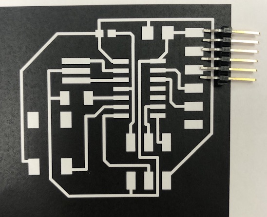
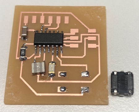
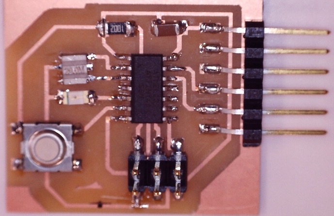
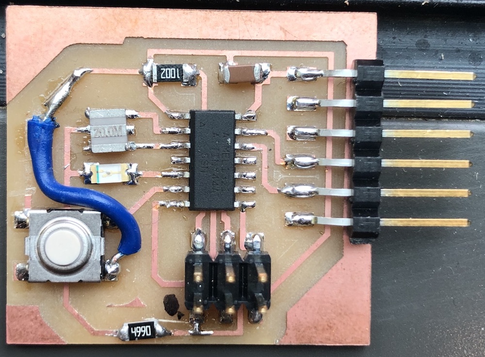
My board before I start hacking it!
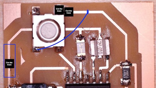
So you should calculate the correct resistor = find LED --> tells you the forward voltage (the amount of voltage you want going across the LED) = 1.8V and the current test (this is the amount of voltage before it blows up) = 10 Am The higher the resister = the dimmer the LED which is less likely to blow the LED This website was useful to understand more about resisitors and what are used for etc. You also need to think about pull-up resisitors which are ones that hold teh voltage high but not over the limit so that when the button is pressed there isn't a sudden peak so there is a clean on and off. A pull-down resisitor works in much the same way other than it pulls down the value to an appropriate low value level. I decided to draw what I was also going to do on my board so that I didn't get it wrong.
I then cut the traces making sure not to make them too large for the resistor to then sit over that cut area.
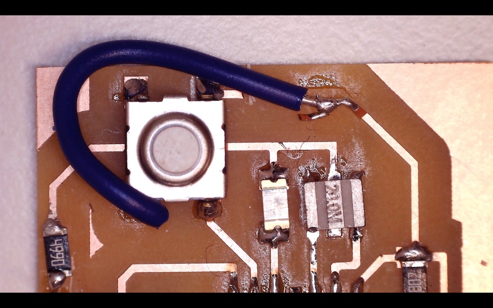
I then placed the resistor onto the trace and soldered it down and then got a wire to connect the button to the other trace so that the circuit was now correct. I checked it and all worked very well so I was pleased, I did manage to pick up some of the trace but this wasn't too bad as it was still connected. Later down the line this did break off as it was so flimsy but I just resoldiered it and made the blue wire shorter so that it had less movement which prevented it from breaking so easily.
In my global feedback it was pointed out that the resisitor was connecting the crystal as well as the GND which would be an issue in the future if I was wanting to do time specific actions with this board. Luckly the board does work as need in this video and I wont be using this board to do anything other than using the button to turn the led on and off. Following this website...
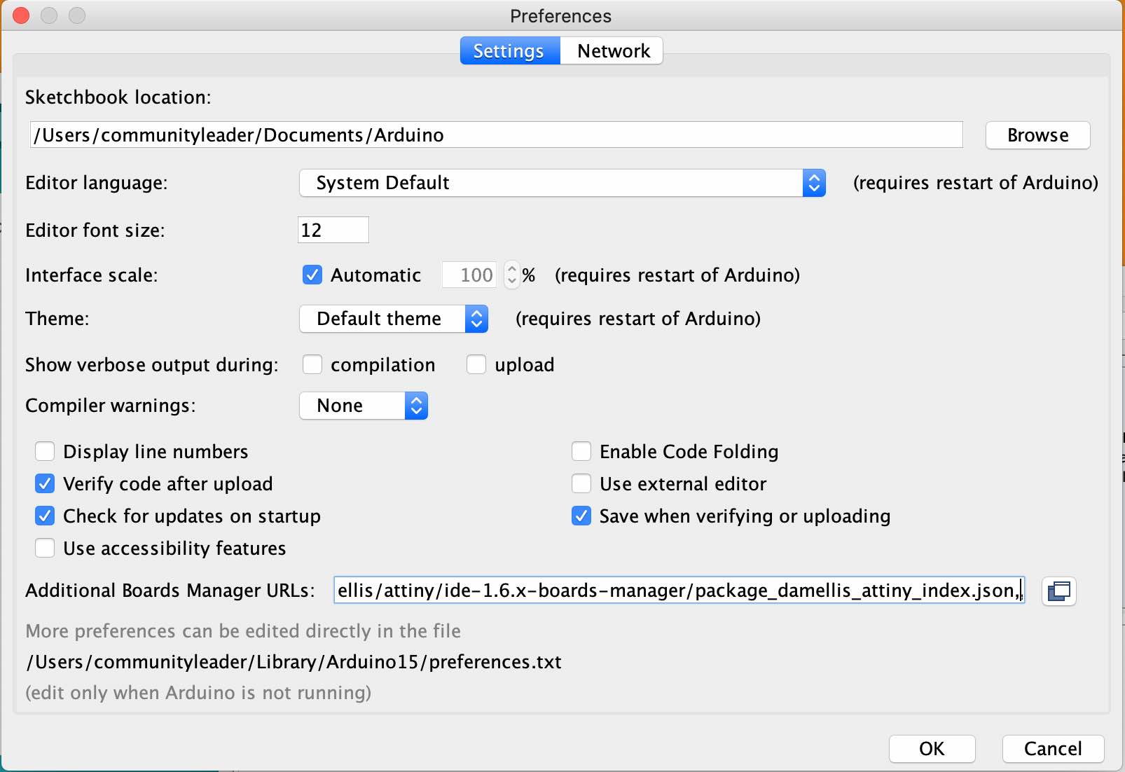
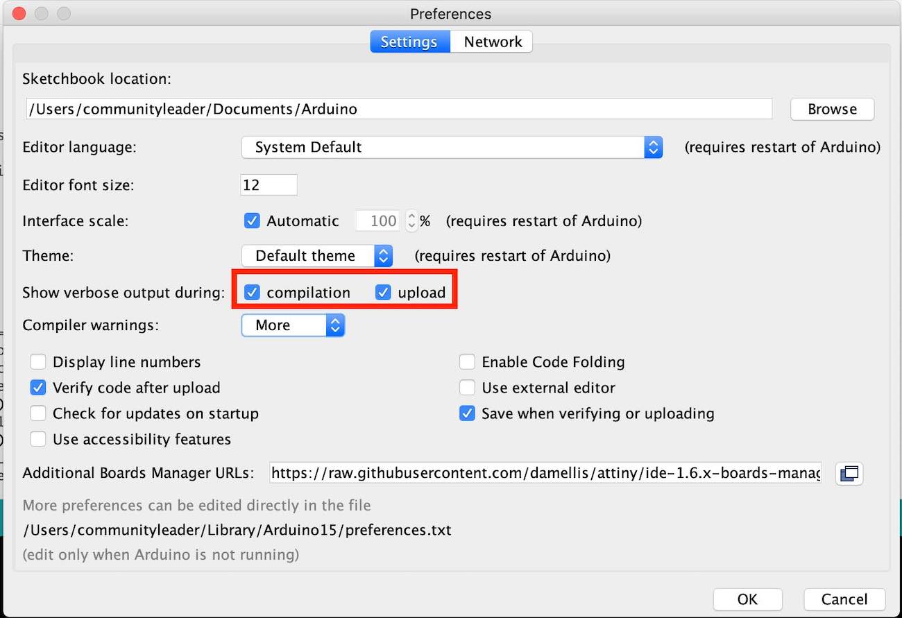
Me telling it to talk loads!! = verbose - MAKE SURE THIS IS ON!
This didn't work for me and came up with an error:
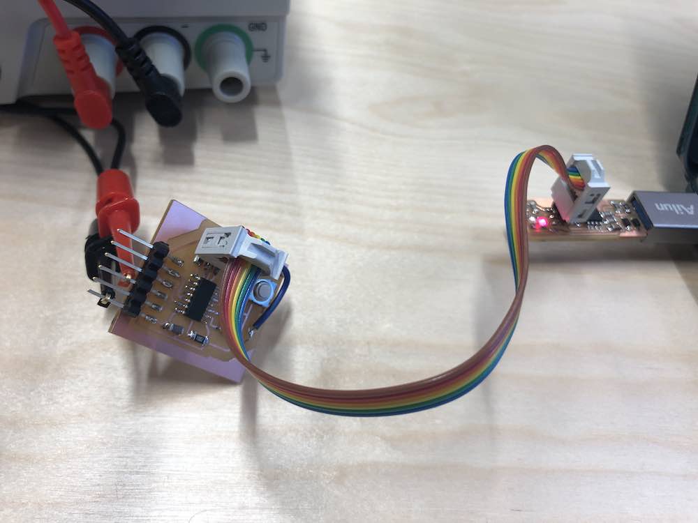
I realised that my board wasn't actually plugged in so I plugged in my board using Jonnys power source which was a plug with a ground and a crocodile clip on the other side. But this didn't work again.
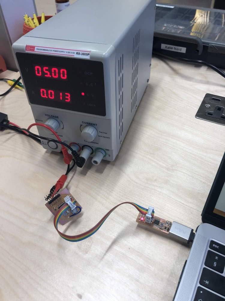
This didn't work again so with an error message of: I then waited till the next day when Andrew was in and asked him what to do, he said to try our actual power box which is made for this with a voltage of 5V coming out onto the boards.
YAY and it worked!
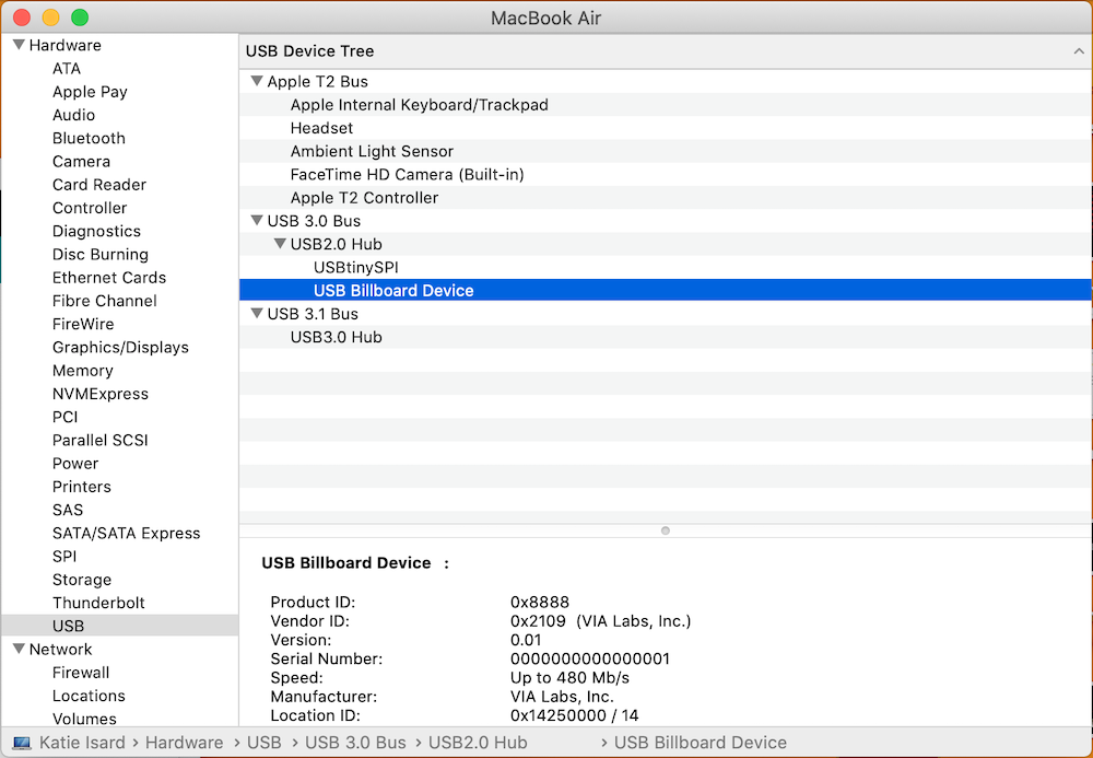
Checking my board is coming up on the USB
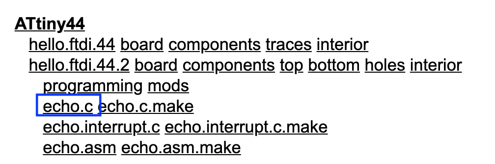
echo.hello is what it sounds like, when you type something in it will then echo that responce. Go to Fab A website and find the ATtiny44 board area...
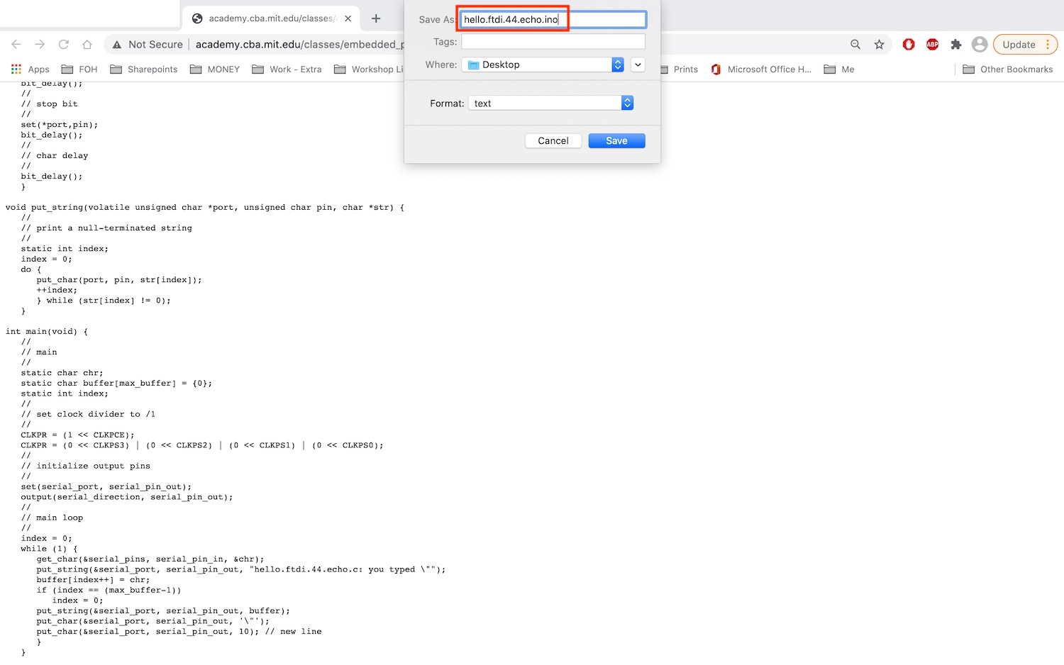
Now open up in Arduino
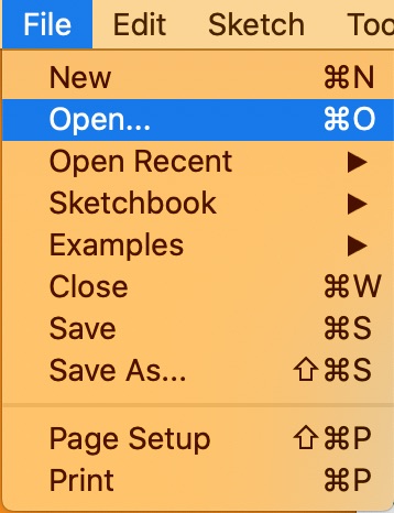
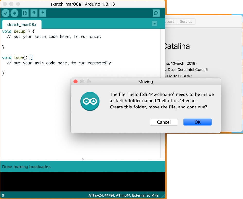
It will try and make you open it up in a file which you done care about press ok
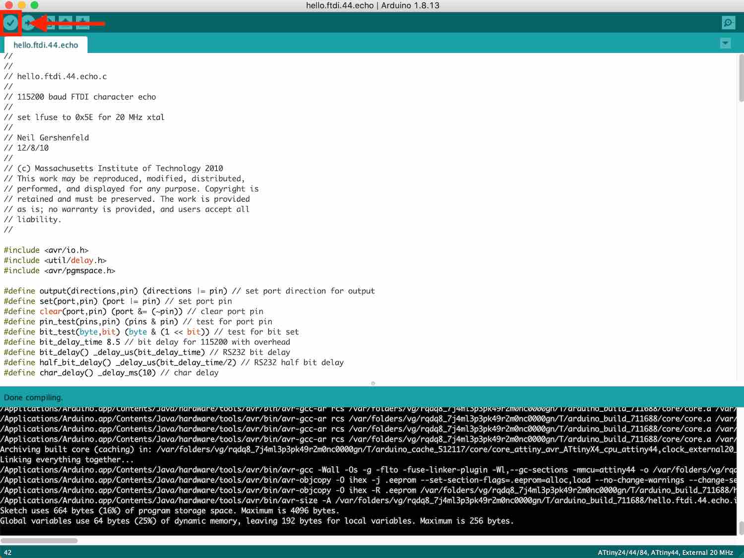
Now compile this
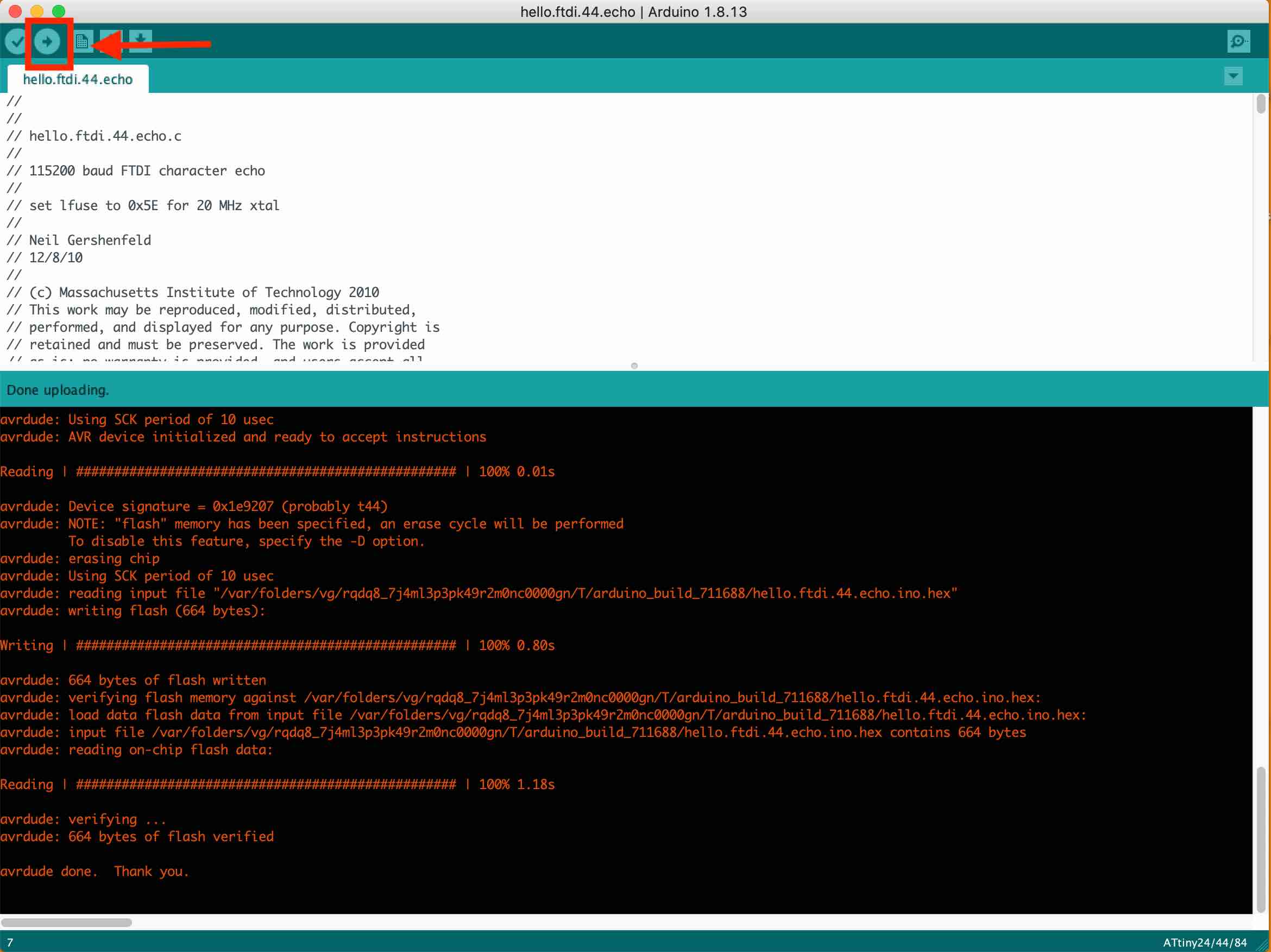
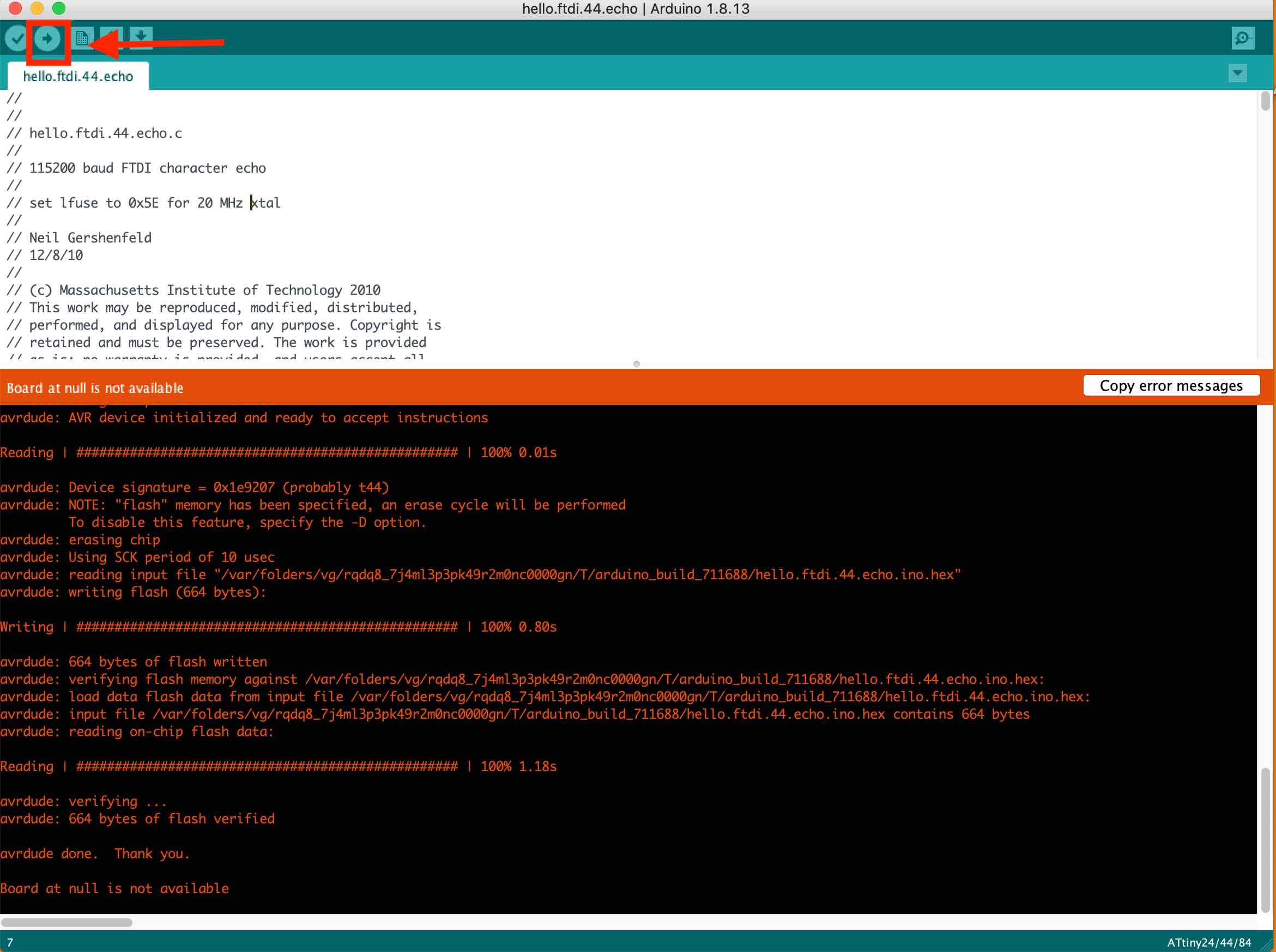
Then upload it
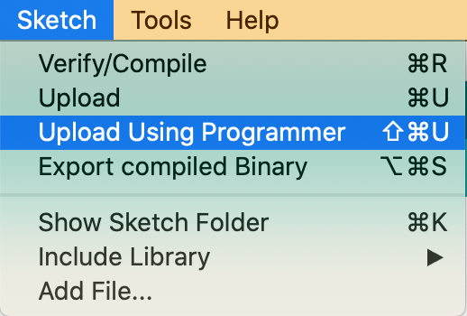
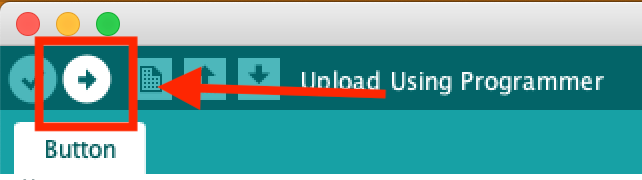
Now upload it using a programmer
I then got an error so I rejigged the board and tried it again and it worked!!
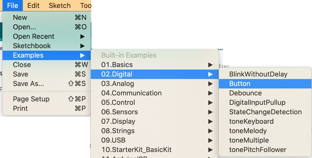
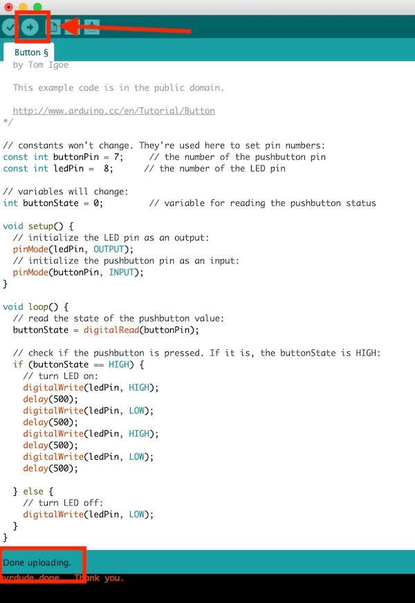
Loop = over and over Opening up an example button so that this is easier for me so I don't have to write the code which is great! Source for Button Arduino sketch:
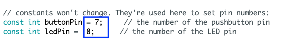
Put the pin that is connected to LED and the Button on the chip in these spaces BUT you need to place the Arduino number not the chip number.
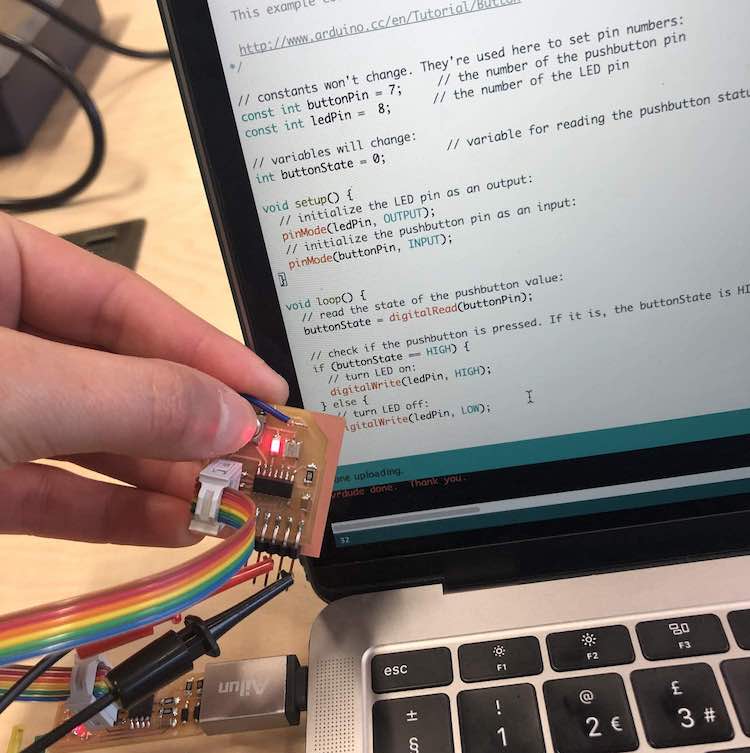
Then upload that to your board…
And now you should press your button and it should FLASH! And mine did WOOHOO
I then had a go and making it flash rather than me having to flash it which was really fun!
PINOUTS
Adding a button
PINOUT diagram
Organising components on the board in Eagle
PINOUTS

Changing width of Traces
Exporting my board/ test paper print
MODS
Cutting board
Figuring out Mistake
Correct Outline and Traces
Soldering
Board 1 (wrong no resistor)

Board 2 (wrong no resistor and button wrong way around)
Fixing my mistakes!
LED - resistor
pull-up and pull-down resisitors
Hero Shot of Board
Global feedback
Setting up board on Arduino
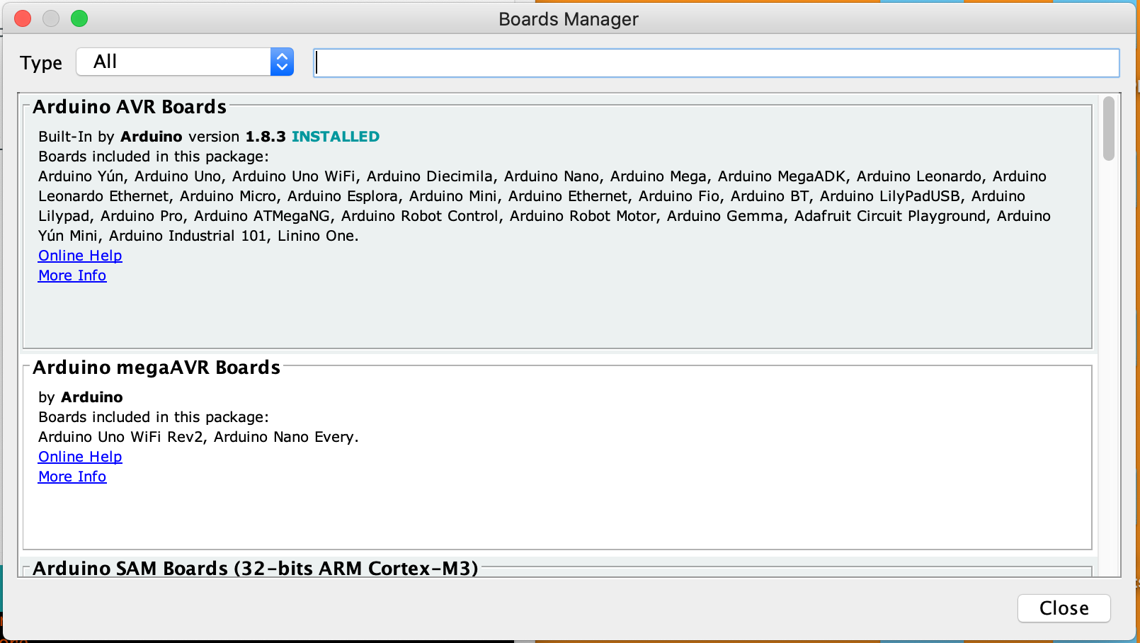
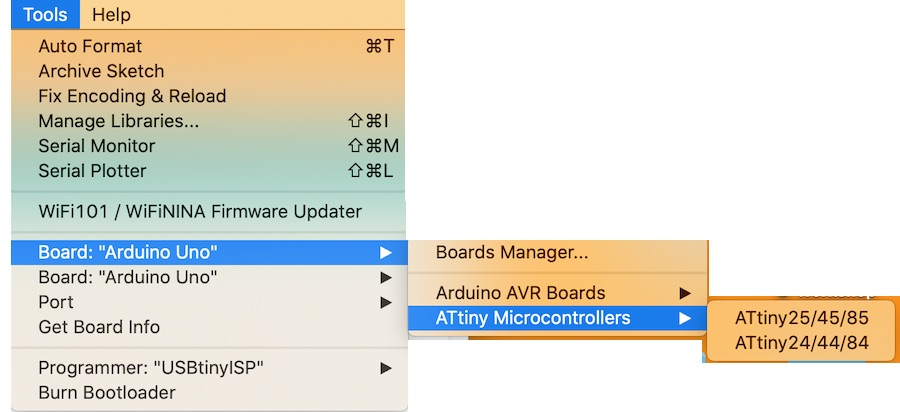
    Close this and go to tool --> Board: 'Arduino Uno' --> ATtiny Microcontrollers --> I will be
    choosing ATtiny24/44/84 as I'm using a ATtiny44 chip
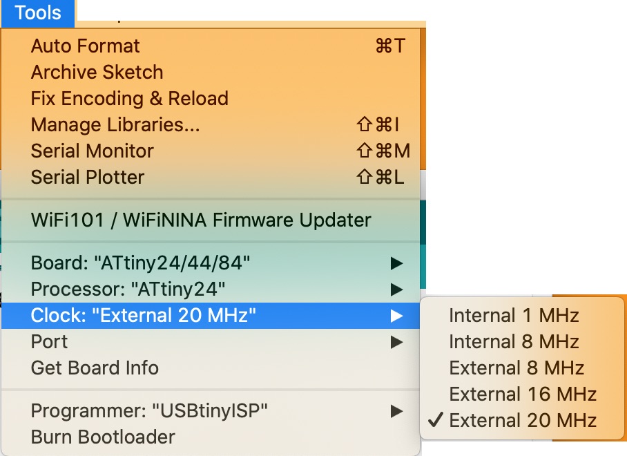
Tools - - > clock - - > external 20 MHz
Clock = Cristal - - this Cristal resinates at 20 MHz per second
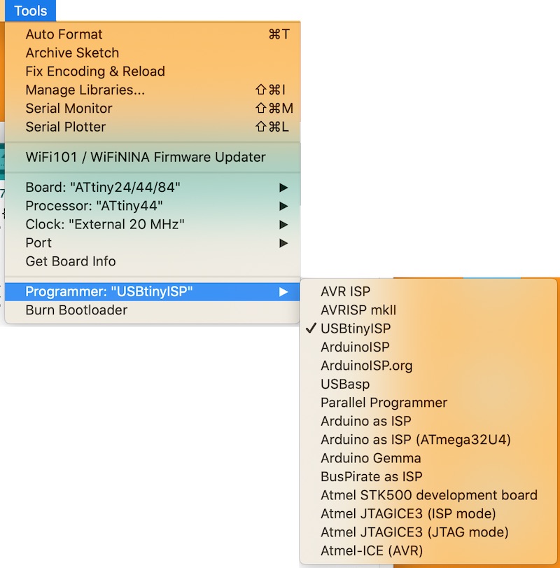
Tools --> Programmer: 'USBtinyISP' (think this is the programmer that I made two weeks ago)
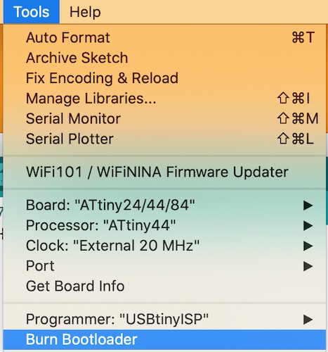
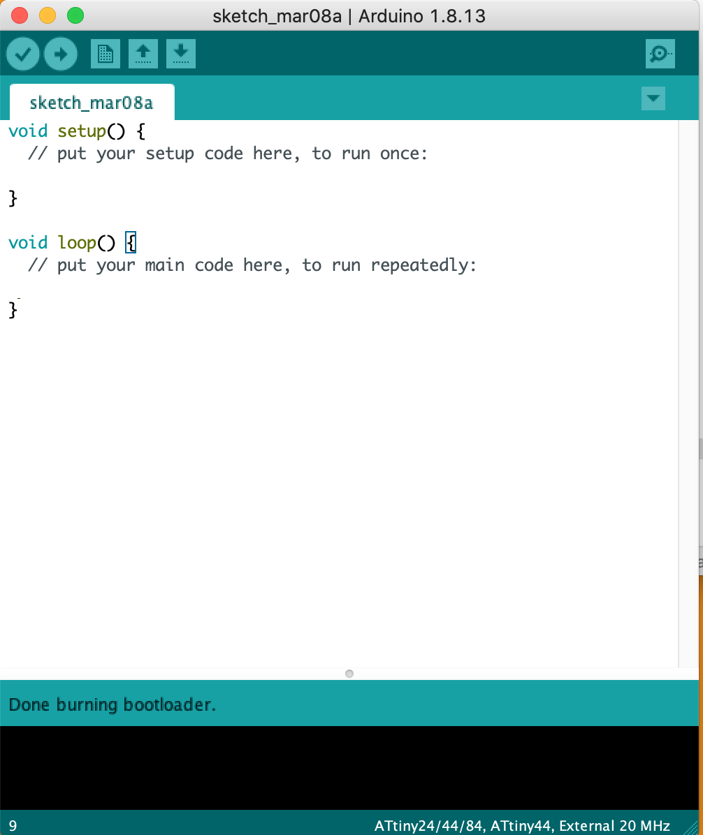
Tools - - > Burn Bootloader
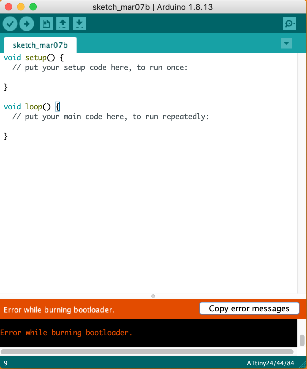
This is the error message:
'Arduino: 1.8.13 (Mac OS X), Board: "ATtiny24/44/84, ATtiny44, External 20 MHz"
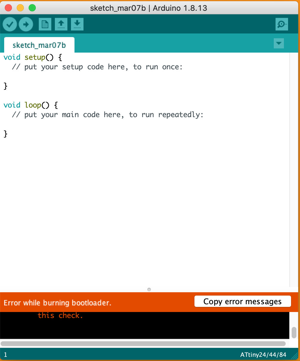
Error while burning bootloader.
avrdude: initialization failed, rc=-1
Double check connections and try again, or use -F to override
this check.
This report would have more information with
"Show verbose output during compilation"
option enabled in File -> Preferences.'
  Arduino: 1.8.13 (Mac OS X), Board: "ATtiny24/44/84, ATtiny44, External 20 MHz"

  avrdude: initialization failed, rc=-1
           Double check connections and try again, or use -F to override
           this check.

  Error while burning bootloader.


  This report would have more information with
  "Show verbose output during compilation"
  option enabled in File - > Preferences.
Programming echo.hello
Making LED flash
ARDUINO
Adding a button to Arduino
  // constants won't change. They're used here to set pin numbers:
    const int buttonPin = 7;     // the number of the pushbutton pin
    const int ledPin =  8;      // the number of the LED pin

  // variables will change:
    int buttonState = 0;         // variable for reading the pushbutton status

  void setup() {
      // initialize the LED pin as an output:
    pinMode(ledPin, OUTPUT);
      // initialize the pushbutton pin as an input:
      pinMode(buttonPin, INPUT);
   }

  void loop() {
      // read the state of the pushbutton value:
      buttonState = digitalRead(buttonPin);

      // check if the pushbutton is pressed. If it is, the buttonState is HIGH:
      if (buttonState == HIGH) {
        // turn LED on:
      digitalWrite(ledPin, HIGH);
   }  else {
      // turn LED off:
      digitalWrite(ledPin, LOW);
   }
  }
Design Files:
Other Pages: