11. Input devices
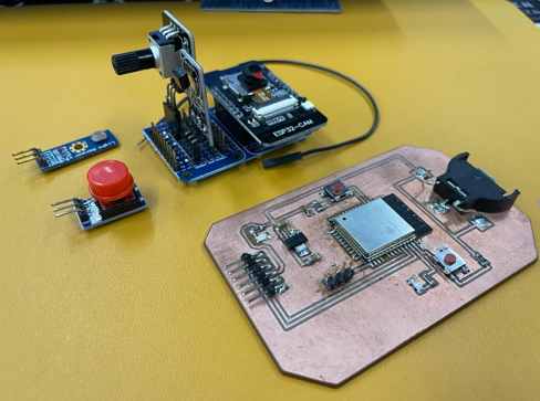
This week learn about input sensors and input devices. I incorporated various input devices into the ESP32-CAM target board. I used digital button, analogue sensors (CDS and potentiometer), capacitive sensing pin and 1 wire bus temperature sensor DS18B20.
Weekly Assignment Requirement
Group assignment
Probe an input device’s analog levels and digital signals
Individual assignment - Measure something: add a sensor to a microcontroller board that you have designed and read it.
Learning outcomes
Demonstrate workflows used in sensing something with input device(s) and MCU board.
Practical work: Making a circuit with input sensors
This week is funny week. Add a sensor to the microcontroller circuit to measure the value. It also measure the value of interest to study FabAcademy. Starting this week, the chip ESP32 will appear frequently.
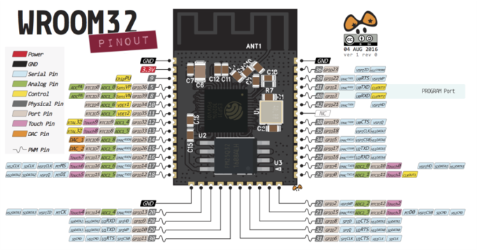
ESP32 Peripherals The ESP32 peripherals include: - 18 Analog-to-Digital Converter (ADC) channels - 3 SPI interfaces - 3 UART interfaces - 2 I2C interfaces - 16 PWM output channels - 2 Digital-to-Analog Converters (DAC) - 2 I2S interfaces - 10 Capacitive sensing GPIOs - The ADC (analog to digital converter) and DAC (digital to analog converter) features are assigned to specific static pins. However, you can decide which pins are UART, I2C, SPI, PWM
Note: ADC2 pins cannot be used when Wi-Fi is used. So, if you’re using Wi-Fi and you’re having trouble getting the value from an ADC2 GPIO, you may consider using an ADC1 GPIO instead, that should solve your problem.
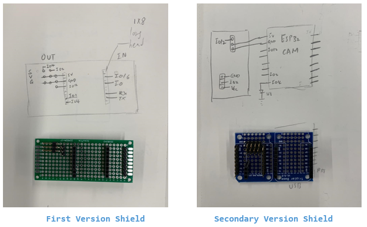
First Version Shield and Secondary Version Shield
I build these two trial developement board with solderable perf board and Mini Triple Socket Triplet Base Shield Board
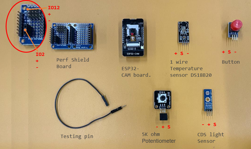
Prepare the components
Based on the breadboard circuit I created, I selected sensors modulus and other components to be used.
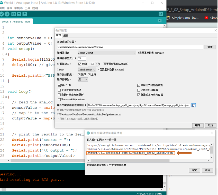
Setup Arduino IDE
On Arduino IDE, we need to set board manager. Open Preference > Additional board manager, then add https://dl.espressif.com/dl/package_esp32_index.json
Program
Then setup board managger from Tool > Board > Boardmanager
Select Board of “ESP32 Wrover Module”. Then it’s done.
Though I could select “ESP32 Dev Module” as well and I could compile/write program to the ESP32 DevkitC, Serial.println() did not work on “ESP32 Dev Module”.
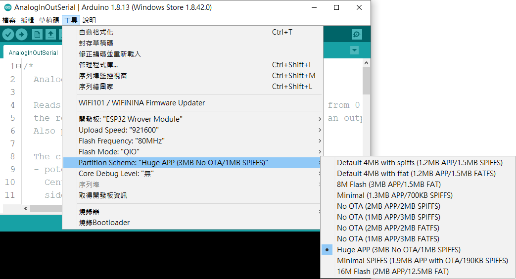
Start writing programs with Arduino this week. Before uploading, you need to select the board type and ESP32-CAM uses the following setting.
These pins can be easily integrated into capacitive pads, and replace mechanical buttons. Additionally, the touch pins can also be used as a wake up source when the ESP32 is in deep sleep.
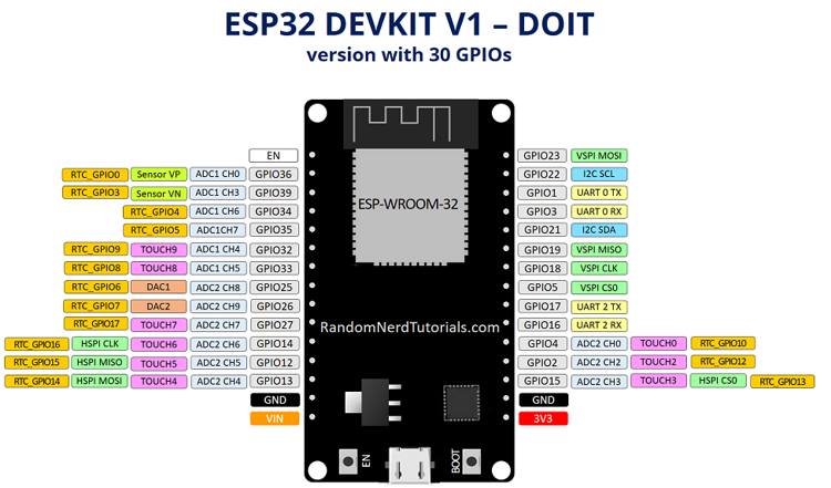
Take a look at your board pinout to locate the 10 different touch sensors – the touch sensitive pins are highlighted in pink color.
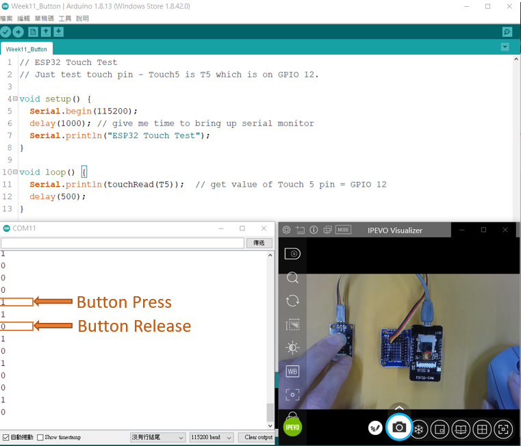
Code Example 1 Touch Pin as Button
Get Touch Test Write program for getting board information over Serial monitor
// ESP32 Touch Test
// Just test touch pin - Touch5 is T5 which is on GPIO 12.

void setup() {
  Serial.begin(115200);
  delay(1000); // give me time to bring up serial monitor
  Serial.println("ESP32 Touch Test");
}

void loop() {
  Serial.println(touchRead(T5));  // get value of Touch 5 pin = GPIO 12
  delay(500);
}
Code Example 2 Touch Pin Test
Get Touch Test Write program for getting board information over Serial monitor
// ESP32 Touch Test
// Just test touch pin - Touch5 is T5 which is on GPIO 12.
const byte LEDPin = 4;
void setup()
{
  Serial.begin(115200);
  delay(100); // give me time to bring up serial monitor
  pinMode(LEDPin, OUTPUT);
  Serial.println("ESP32 Touch Test");
}

void loop()
{
  delay(100);
  Serial.println(touchRead(T5));  // get value using T5 (GPIO 12)
  if(touchRead(T5)<50)
  digitalWrite(LEDPin, HIGH);
  else
  digitalWrite(LEDPin,LOW);
}
The ESP32 touch pins can sense variations in anything that holds an electrical charge. The ESP32 has 10 capacitive touch GPIOs. These GPIOs can sense variations in anything that holds an electrical charge, like the human skin. So they can detect variations induced when touching the GPIOs with a finger.
Code Example 3 Analogue Read Test with CDS and potentiometer
int sensorValue = 0;        // value read from the pot
int outputValue = 0;        // value output to the PWM (analog out)
void setup()
{
  Serial.begin(115200);
  delay(100); // give me time to bring up serial monitor

  Serial.println("ESP32 Analogue Test");
}

void loop()
{
  // read the analog in value:
  sensorValue = analogRead(12);
  // map it to the range of the analog out:
  outputValue = map(sensorValue, 0, 1023, 0, 255);
  // print the results to the Serial Monitor:
  Serial.print("sensor = ");
  Serial.print(sensorValue);
  Serial.print("\t output = ");
  Serial.println(outputValue);
  // wait 2 milliseconds before the next loop for the analog-to-digital
  // converter to settle after the last reading:
  delay(2);

A potentiometer is a simple knob that provides a variable resistance, which we can read into the Arduino board as an analog value. For example, that value controls the rate at which an LED blinks.
I connect three wires to the Arduino board. The analog input GPIO 12 connect to the signal pin of the potentiometer.
Code Example 4 Onewire Temperature (Single DS18B20)
The DS18B20 temperature sensor is a one-wire digital temperature sensor. This means that it just requires one data line (and GND) to communicate with your ESP32.
Installing Libraries
To interface with the DS18B20 temperature sensor, you need to install the One Wire library by Paul Stoffregen and the Dallas Temperature library. Follow the next steps to install those libraries.
-
Open your Arduino IDE and go to Sketch > Include Library > Manage Libraries. The Library Manager should open.
-
Type “onewire” in the search box and install OneWire library by Paul Stoffregen.
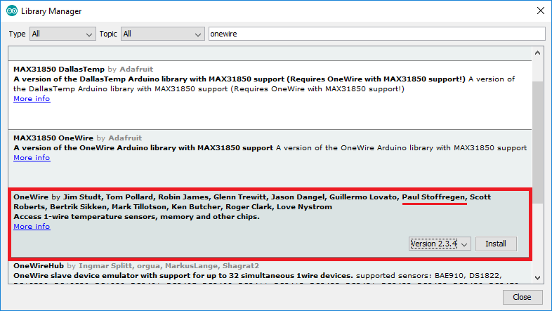
- Then, search for “Dallas” and install DallasTemperature library by Miles Burton.

After installing the libraries, restart your Arduino IDE.
After installing the required libraries, you can upload the code to the ESP32. The following code reads temperature from the DS18B20 temperature sensor and displays the readings on the Arduino IDE Serial Monitor.
/*********
Rui Santos
Complete project details at https://RandomNerdTutorials.com
*********/
// Import required libraries
#ifdef ESP32
#include <WiFi.h>
#include <ESPAsyncWebServer.h>
#else
#include <Arduino.h>
#include <ESP8266WiFi.h>
#include <Hash.h>
#include <ESPAsyncTCP.h>
#include <ESPAsyncWebServer.h>S
#endif
#include <OneWire.h>
#include <DallasTemperature.h>
// Data wire is connected to GPIO 4
#define ONE_WIRE_BUS 2
// Setup a oneWire instance to communicate with any OneWire devices
OneWire oneWire(ONE_WIRE_BUS);
// Pass our oneWire reference to Dallas Temperature sensor
DallasTemperature sensors(&oneWire);
// Variables to store temperature values
String temperatureF = "";
String temperatureC = "";
// Timer variables
unsigned long lastTime = 0;
unsigned long timerDelay = 3000;
// Replace with your network credentials
const char* ssid = "fablab";
const char* password = "27796851";
// Create AsyncWebServer object on port 80
AsyncWebServer server(80);
String readDSTemperatureC() {
// Call sensors.requestTemperatures() to issue a global temperature and Requests to all devices on the bus
sensors.requestTemperatures();
float tempC = sensors.getTempCByIndex(0);
if(tempC == -127.00) {
Serial.println("Failed to read from DS18B20 sensor");
return "--";
} else {
Serial.print("Temperature Celsius: ");
Serial.println(tempC);
}
return String(tempC);
}
String readDSTemperatureF() {
// Call sensors.requestTemperatures() to issue a global temperature and Requests to all devices on the bus
sensors.requestTemperatures();
float tempF = sensors.getTempFByIndex(0);
if(int(tempF) == -196){
Serial.println("Failed to read from DS18B20 sensor");
return "--";
} else {
Serial.print("Temperature Fahrenheit: ");
Serial.println(tempF);
}
return String(tempF);
}
const char index_html[] PROGMEM = R"rawliteral(
<!DOCTYPE HTML><html>
<head>
<meta name="viewport" content="width=device-width, initial-scale=1">
<link rel="stylesheet" href="https://use.fontawesome.com/releases/v5.7.2/css/all.css" integrity="sha384-fnmOCqbTlWIlj8LyTjo7mOUStjsKC4pOpQbqyi7RrhN7udi9RwhKkMHpvLbHG9Sr" crossorigin="anonymous">
<style>
html {
font-family: Arial;
display: inline-block;
margin: 0px auto;
text-align: center;
}
h2 { font-size: 3.0rem; }
p { font-size: 3.0rem; }
.units { font-size: 1.2rem; }
.ds-labels{
font-size: 1.5rem;
vertical-align:middle;
padding-bottom: 15px;
}
</style>
</head>
<body>
<h2>ESP DS18B20 Server</h2>
<p>
<i class="fas fa-thermometer-half" style="color:#059e8a;"></i>
<span class="ds-labels">Temperature Celsius</span>
<span id="temperaturec">%TEMPERATUREC%</span>
<sup class="units">°C</sup>
</p>
<p>
<i class="fas fa-thermometer-half" style="color:#059e8a;"></i>
<span class="ds-labels">Temperature Fahrenheit</span>
<span id="temperaturef">%TEMPERATUREF%</span>
<sup class="units">°F</sup>
</p>
</body>
<script>
setInterval(function ( ) {
var xhttp = new XMLHttpRequest();
xhttp.onreadystatechange = function() {
if (this.readyState == 4 && this.status == 200) {
document.getElementById("temperaturec").innerHTML = this.responseText;
}
};
xhttp.open("GET", "/temperaturec", true);
xhttp.send();
}, 10000) ;
setInterval(function ( ) {
var xhttp = new XMLHttpRequest();
xhttp.onreadystatechange = function() {
if (this.readyState == 4 && this.status == 200) {
document.getElementById("temperaturef").innerHTML = this.responseText;
}
};
xhttp.open("GET", "/temperaturef", true);
xhttp.send();
}, 10000) ;
</script>
</html>)rawliteral";
// Replaces placeholder with DS18B20 values
String processor(const String& var){
//Serial.println(var);
if(var == "TEMPERATUREC"){
return temperatureC;
}
else if(var == "TEMPERATUREF"){
return temperatureF;
}
return String();
}
void setup(){
// Serial port for debugging purposes
Serial.begin(115200);
Serial.println();
// Start up the DS18B20 library
sensors.begin();
temperatureC = readDSTemperatureC();
temperatureF = readDSTemperatureF();
// Connect to Wi-Fi
WiFi.begin(ssid, password);
Serial.println("Connecting to WiFi");
while (WiFi.status() != WL_CONNECTED) {
delay(500);
Serial.print(".");
}
Serial.println();
// Print ESP Local IP Address
Serial.println(WiFi.localIP());
// Route for root / web page
server.on("/", HTTP_GET, [](AsyncWebServerRequest *request){
request->send_P(200, "text/html", index_html, processor);
});
server.on("/temperaturec", HTTP_GET, [](AsyncWebServerRequest *request){
request->send_P(200, "text/plain", temperatureC.c_str());
});
server.on("/temperaturef", HTTP_GET, [](AsyncWebServerRequest *request){
request->send_P(200, "text/plain", temperatureF.c_str());
});
// Start server
server.begin();
}
void loop(){
if ((millis() - lastTime) > timerDelay) {
temperatureC = readDSTemperatureC();
temperatureF = readDSTemperatureF();
lastTime = millis();
}
}
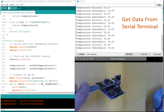
Get Data From Serial Terminal
Get Data From ESP32 Web Server
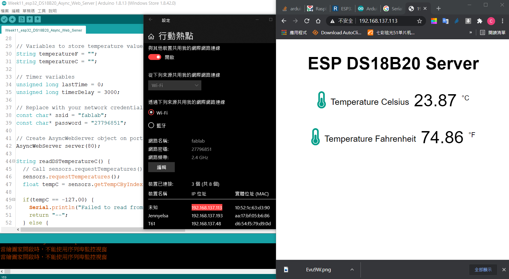
Build a simple web server to display the sensor readings.
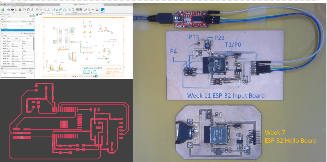
New PCB Design for Week11 Input Devices
I started with PCB design using Fusion360 software. Referred by Week7 - electronic design documentation for designing my PCB.
Components used
ESP-WROOM-32 x 1 Resistor 100ohm x 2 Resistor 10kohm x 2 Capacitor 10uf x 2 Capacitor 1uf x 2 sensor header (3x1 pin) x 2 FTDI header (1x6 pin) x1 switch x 1 1206 LED x 2 button x 2
ESP32 ADC – Read Analog Values with Arduino IDE
P4 or P13 can connect potentiometer as analogue input. Analog reading is useful to read values from variable resistors like potentiometers, or analog sensors. Reading analog inputs with the ESP32 is as easy as using the analogRead(GPIO) function, that accepts as argument, the GPIO you want to read.
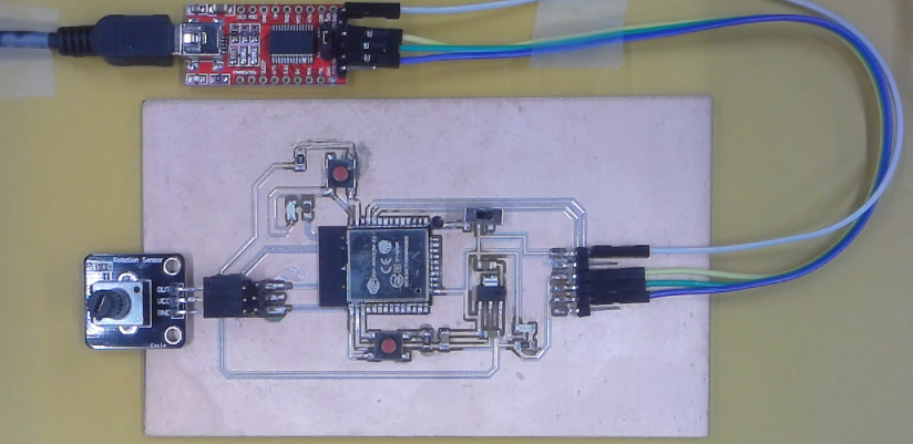
Wire a potentiometer to your ESP32. The potentiometer OUT pin should be connected to GPIO P4.
Analog Inputs (ADC)
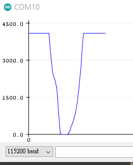
The voltage measured is then assigned to a value between 0 and 4095, in which 0 V corresponds to 0, and 3.3 V corresponds to 4095. Any voltage between 0 V and 3.3 V will be given the corresponding value in between.
// Potentiometer is connected to GPIO 4
const int potPin = 4;

// variable for storing the potentiometer value
int potValue = 0;

void setup() {
  Serial.begin(115200);
  delay(1000);
}

void loop() {
  // Reading potentiometer value
  potValue = analogRead(potPin);
  Serial.println(potValue);
  delay(500);
}
Touch Inputs
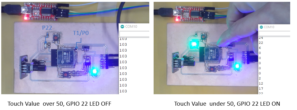
The ESP32 touch pins can sense variations in anything that holds an electrical charge. They are often used to wake up the ESP32 from deep sleep. To read the value of the ESP32 touch pins, use the touchRead(GPIO) function, that accepts as argument, the GPIO you want to read.
// ESP32 Touch Test
// Just test touch pin - Touch1 is T1 which is on GPIO 0.
const byte LEDPin = 22;
void setup()
{
  Serial.begin(115200);
  delay(100); // give me time to bring up serial monitor
  pinMode(LEDPin, OUTPUT);
  Serial.println("ESP32 Touch Test");
}

void loop()
{
  delay(100);
  Serial.println(touchRead(T1));  // get value using T5 (GPIO 12)
  if(touchRead(T1)<50)
  digitalWrite(LEDPin, HIGH);
  else
  digitalWrite(LEDPin,LOW);
}
Here is the file W11-ESP32-CMY.fsch and W11-ESP32-CMY.fbrd for ESP32 Input Board.
Group assignment - Input Devices
Probe an input device’s analog levels and digital signals
Probe an input device’s digital levels
ESP32 touch pins can be easily integrated into capacitive pads, and replace mechanical buttons. Additionally, the touch pins can also be used as a wake up source when the ESP32 is in deep sleep.
Take a look at your board pinout to locate the 10 different touch sensors – the touch sensitive pins are highlighted in pink color.
Code Touch Pin as Button
Get Touch Test Write program for getting board information over Serial monitor
// ESP32 Touch Test
// Just test touch pin - Touch5 is T5 which is on GPIO 12.

void setup() {
  Serial.begin(115200);
  delay(1000); // give me time to bring up serial monitor
  Serial.println("ESP32 Touch Test");
}

void loop() {
  Serial.println(touchRead(T5));  // get value of Touch 5 pin = GPIO 12
  delay(500);
}
Probe an input device’s analog levels
Code Touch Pin Analgue Test
Get Touch Test Write program for getting board information over Serial monitor
// ESP32 Touch Test
// Just test touch pin - Touch5 is T5 which is on GPIO 12.
const byte LEDPin = 4;
void setup()
{
  Serial.begin(115200);
  delay(100); // give me time to bring up serial monitor
  pinMode(LEDPin, OUTPUT);
  Serial.println("ESP32 Touch Test");
}

void loop()
{
  delay(100);
  Serial.println(touchRead(T5));  // get value using T5 (GPIO 12)
  if(touchRead(T5)<50)
  digitalWrite(LEDPin, HIGH);
  else
  digitalWrite(LEDPin,LOW);
}
The ESP32 touch pins can sense variations in anything that holds an electrical charge. The ESP32 has 10 capacitive touch GPIOs. These GPIOs can sense variations in anything that holds an electrical charge, like the human skin. So they can detect variations induced when touching the GPIOs with a finger.
Code Analogue Read Test with CDS and potentiometer
int sensorValue = 0;        // value read from the pot
int outputValue = 0;        // value output to the PWM (analog out)
void setup()
{
  Serial.begin(115200);
  delay(100); // give me time to bring up serial monitor

  Serial.println("ESP32 Analogue Test");
}

void loop()
{
  // read the analog in value:
  sensorValue = analogRead(12);
  // map it to the range of the analog out:
  outputValue = map(sensorValue, 0, 1023, 0, 255);
  // print the results to the Serial Monitor:
  Serial.print("sensor = ");
  Serial.print(sensorValue);
  Serial.print("\t output = ");
  Serial.println(outputValue);
  // wait 2 milliseconds before the next loop for the analog-to-digital
  // converter to settle after the last reading:
  delay(2);
A potentiometer is a simple knob that provides a variable resistance, which we can read into the Arduino board as an analog value. For example, that value controls the rate at which an LED blinks.
I connect three wires to the Arduino board. The analog input GPIO 12 connect to the signal pin of the potentiometer.