Group assignment:
- Characterize the design rules for your PCB production process: document feeds, speeds, plunge rate, depth of cut (traces and outline) and tooling.
- document your work (in a group or individually)
Individual assignment:
- Make an in-circuit programmer by milling and stuffing the PCB, test it, then optionally try other PCB fabrication process.
Group assignment:
Step 1 ( Download the files )

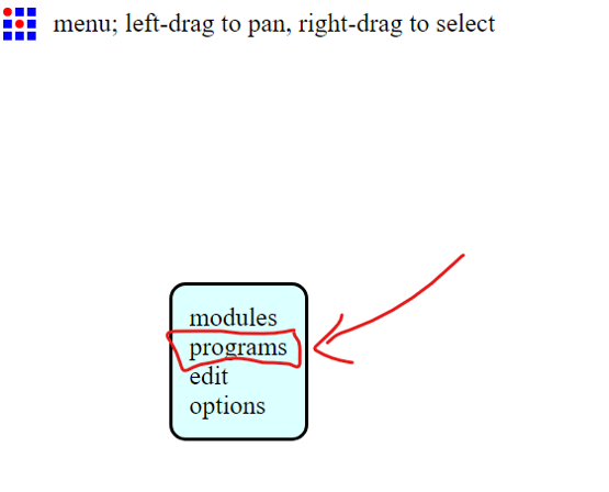
Step 2: prepare the file on mods
Open MIT Mods to create the toolpath files.
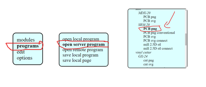
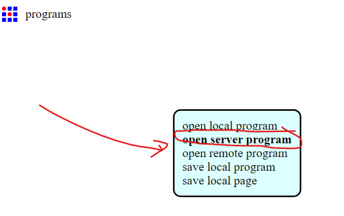
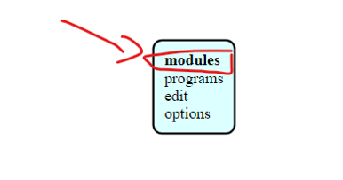
Right Click then –» Prgoram –» Open Server Program –» SRM-20 PNG
this dpends on the machine you have and the file format , I have monoFab SRM-20 and the file format for the traces are in PNG
then Click select png file
Once import the png file, select the tool diameter (depends on the milling bits we use).
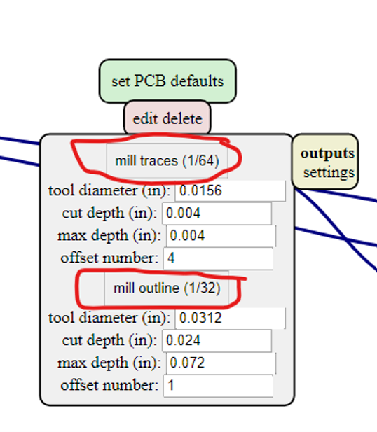
- For Milling the Traces i use 1/64
- For Cutting the Boarder i use 1/32
When Yuo Click to One of this tow option the default setting will be passed to the second module
Cut depth and maximum depth suppose to be the thickness of copper, so we set it into 0.1. Usually 0.4mm for the interial content and 0.8 mm for the outline to cut the PCB off. 0.4 mm milling bits should use offset number 4 and 0.3 mm one could use offset number 5-6.
Step 2: SEND THE FILES TO A ROLAND CNC
-
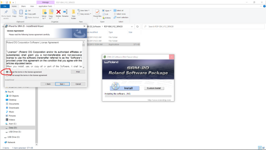
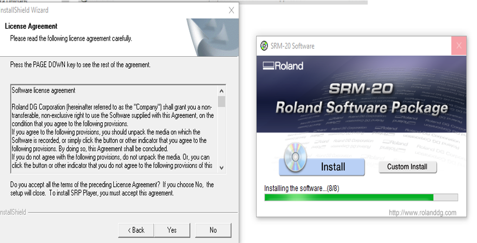
make sure that you have the software ready installed in the lab , if not you have to install it and go through this guide
-
in my case the sofware was not ready so i had to download the software and go through the guide
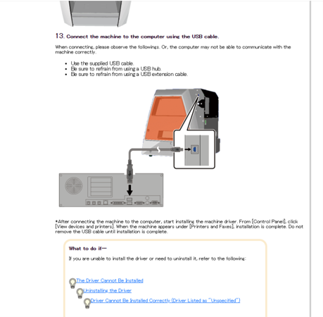
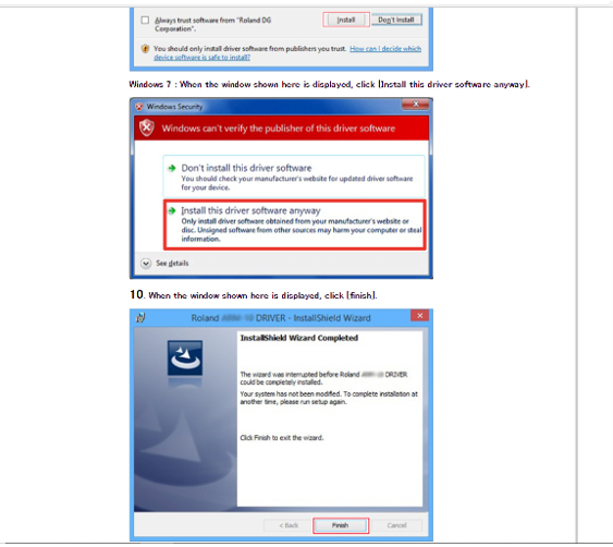
- then install the software that needed for the machine
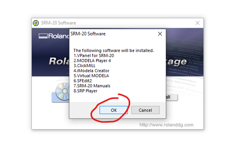
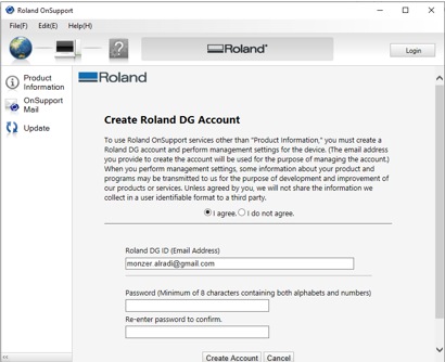
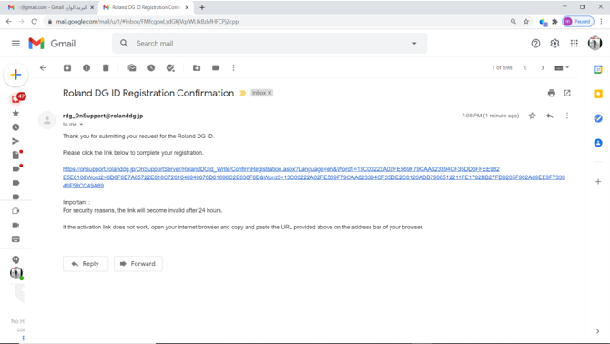
- then you need to create an account from the roland support, then activate your account
Turn on Roland Modela and the computer and open VPanel for SRM-20 A nice tip is to warm the spindle for 10 min at mid Rpm before using it.
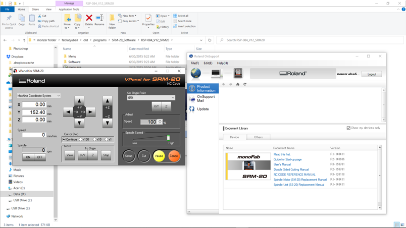
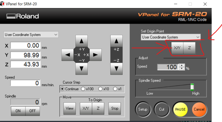
Step 3: Set the X/Y/Z zeros
Decide where to set the origin on your board.It depends on where you taped your board. When you have choosen the position click on Set origin X/Y in Vpanel
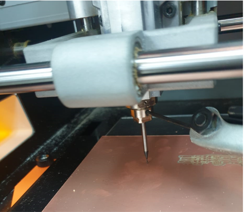
Set Z zero,the Z is slightly more complicated
Move the Z slowly with the control panel around 3-5 mm above the PCB plate. Now we are going to do the Z manually by loosing the collect screw and land the endmill on the surface. Slowly loosen the mill bit with an allen wrench so that it drops gently to the surface of your board.
- Now save the XYZ origin in the Vpanel control panel.
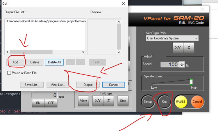
Step 7: Send the traces!
Click “Cut” on the control panel. A new window will appear where you will select your traces cutting file, now click Output and the machine should start
this week is the least creative week till now , we have to follow the instruction in order to make in -circuit programmer
which programmer to use
since i decided to start my electronic journey with attiny45 due to its bulk availability in our lab, it will be the best choice to program it with FabTinyISP
FabTinyISP
The FabTinyStar is yet another version of an AVR ISP programmer/board that can be produced in a fab lab using a milled PCB and readily available components. The project is based on the efforts of many people. For more history of the FabTinyStar and the people who have contributed to it, please refer to Zaerc’s FabTinyStar page.
Introduction
This version (the “FabTinyISP Minimal” is a minor revision to Zaerc’s version 0.3 (Bas), with small modifications:
The reset switch and target power switch have been removed. The reset switch adds cost and isn’t incredibly useful on an ISP programmer, as the target can be easily reset through a software command. The target power swtich has been removed as providing power to the target through the programming port is usually discouraged. Users who understand the implications of this are welcome to build one of the FTS designs with the switch. The copper ground pour has been removed and replaced with individual ground traces; this allows novice solderers to mill away more of the copper. All components solder to clearly defined pads on both sides. The extra pads connecting to the USB data lines were removed; this version is targeted solely at being an ISP programmer rather than being a general-purpose tiny45 board. The PTC thermistor was removed; as this part currently isn’t in the inventory most users would build it with a 0Ω resistor anyway. As the option to provide target power has been removed, it should be much more difficult to create a condition where the polyfuse would be needed. The Makefile has been replaced. Targets for programming the fuses on an ATtiny45 have been added. The original Makefile also results in problems on case-insensitive filesystems (i.e. Windows). This page describes how to build, program, test, and debug the board.
Notes
One possible point of confusion in this document is that the device you’re building will become an AVR programmer, but you also need a working AVR programmer in the process of building it. Your board refers to the new programmer that you are building. Programmer refers to the working programmer that you’ll use to initialize yours. At the end of this document, your board becomes a programmer.
PCB Fabrication
Download the PNG files for the traces and the board outline:
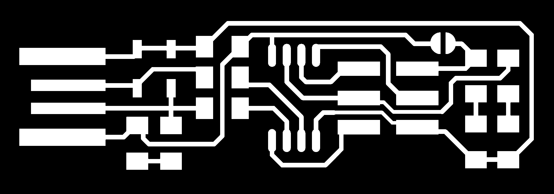
The Altium source files are available here if you want to modify the design.
Since there are different processes for milling on different machines, this is not described here. Please refer to a PCB milling reference that’s applicable to the equipment in your shop.
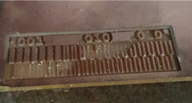
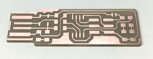
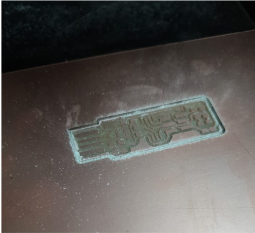
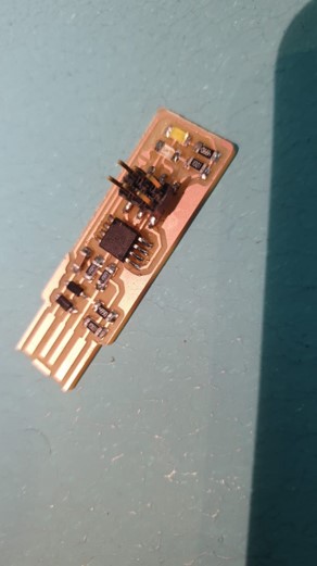
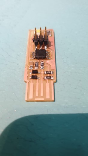
The finished PCB should look something like this:
Step 1 obtain the files: Find or Design a Circuit Board
make sure to download the Traces and Outline Cutout and save them in your computer as png
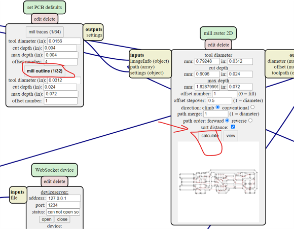
Step 2: MODS - Setup (1/64)
MODS is the new FABMODULES it more capable and works by connecting nodes to develop each process. You can customize you own workflows by loading different modules or use an already precompiled program.
In our case we are going to use a precompiled program and add a module to save automatically in our computer instead of connecting directly to the machine.
Open mods in your browser recommended firefox/chrome
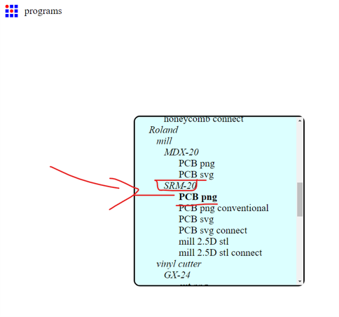
- Right click anywhere and select PROGRAMS – select OPEN SERVER PROGRAM
- select ROLAND > MILL > SMR20-MDX20(choose the machine you will use) and now PCB
- iam using roland SRM-20 and the file is png so i selected this option
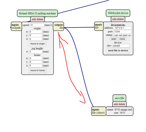
- We need to add another module to make it save the file automatically. So we need to look for the program/component that outputs the file. In this case Roland SRM-20 milling machine
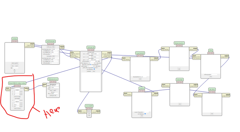
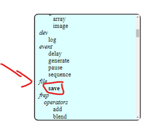
- Right click anywhere in the white space and select MODULE > OPEN SERVE MODULE > SAVE FILE
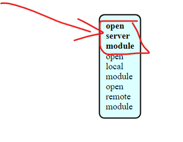
- Now connect the elements by clicking on OUTPUT of RolandSrm-20milling machine and clicking again in INPUT of save file module to make the connection/ wiring between them.
 Done!
Done!
Step 3: MODS - Traces (1/64)
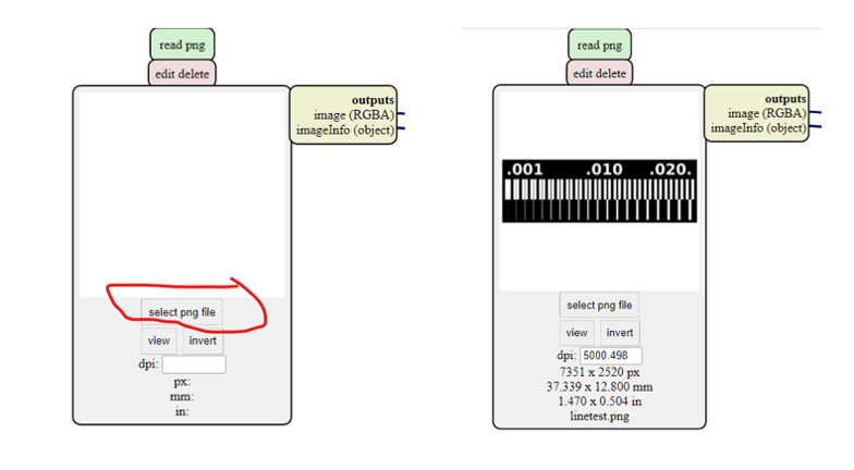
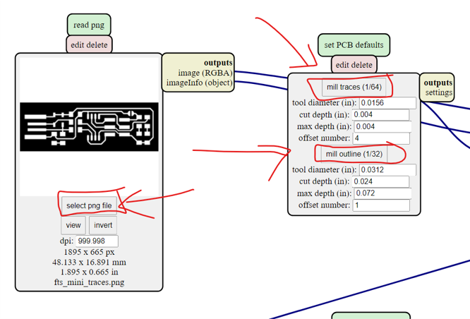
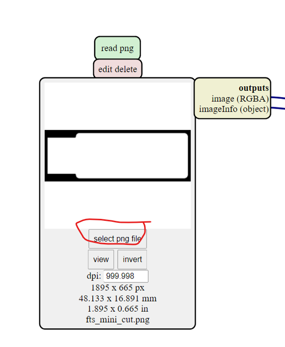
Open your traces image file (This is the one with lines that will form the wires between your components.)
-
Go to READ PNG MODULE SELECT- PNG FILE - select your traces image
-
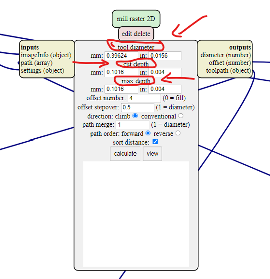
In SET PCB Default module click in MILL TRACES 1/64
-
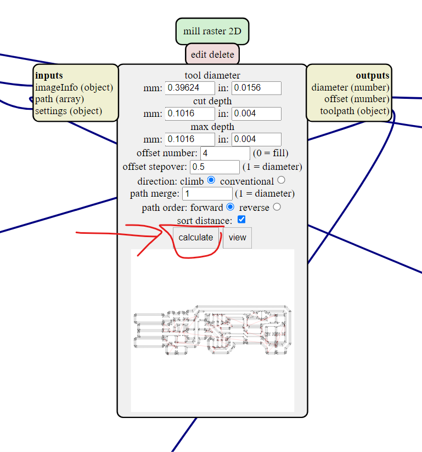
In Mill Raster 2D module click in Calculate
 The file will be saved automatically into your download folder.
In module Roland SRM-20 milling machine Origin
x0(mm) - 0 y0(mm) - 0 z0(mm) - 0 These x0,y0,z0 are for setting up an offset from the origin save in zjopg - 12 This is the z distance that the mill will go up between the air travellings Speed - 4 or 3 mm/s for new end mills x/y/x home is the parking position after finishing the cut
Step 4: MODS - Outcut/Holes (1/32)
Open your traces image file (This is the one with lines that will form the wires between your components.)
Go to READ PNG MODULE SELECT- PNG FILE - select your traces image
- In SET PCB Default module click in MILL TRACES 1/32
- In Mill Raster 2D module click in Calculate
The file will be saved automatically into your download folder. x0(mm) - 0 y0(mm) - 0 z0(mm) - 0 zjopg - 12 Speed - 0.5 Click “calculate”(you will see the path calculating), when the process will finish it will “automatically be saved into your downloads folder”
Step 5: SEND THE FILES TO A ROLAND CNC
-
make sure that you have the software ready installed in the lab , if not you have to install it and go through this guide
-
in my case the sofware was not ready so i had to download the software and go through the guide
- then install the software that needed for the machine
- then you need to create an account from the roland support, then activate your account
Turn on Roland Modela and the computer and open VPanel for SRM-20 A nice tip is to warm the spindle for 10 min at mid Rpm before using it.
Step 6: Set the X/Y/Z zeros
Decide where to set the origin on your board.It depends on where you taped your board. When you have choosen the position click on Set origin X/Y in Vpanel
Set Z zero,the Z is slightly more complicated
Move the Z slowly with the control panel around 3-5 mm above the PCB plate. Now we are going to do the Z manually by loosing the collect screw and land the endmill on the surface. Slowly loosen the mill bit with an allen wrench so that it drops gently to the surface of your board.
- Now save the XYZ origin in the Vpanel control panel.
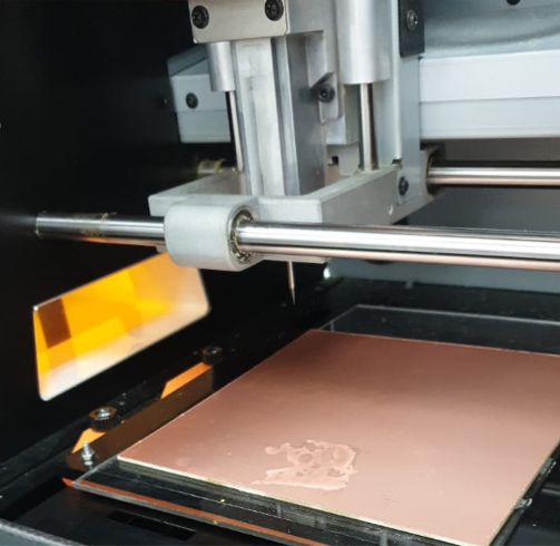
Step 7: Send the traces!
Click “Cut” on the control panel. A new window will appear where you will select your traces cutting file, now click Output and the machine should start
- now the machine will start to cut the traces
- now the machine will start to cut the traces
Step 8: Send the outcut/holes!
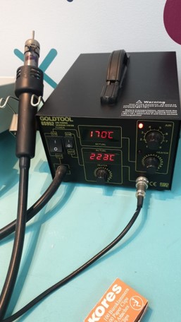
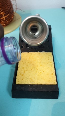
Step 9: prepare solder station
- power up the solder station
- add water for the sponge
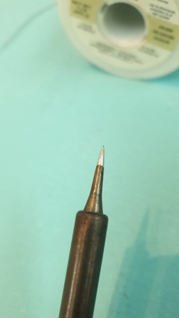
- clean the tip of iron
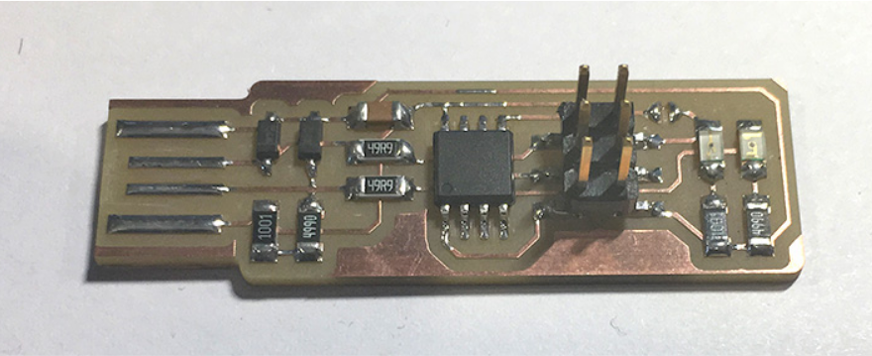
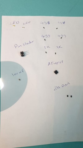
Step 10: prepare the component and add glue to the pcb
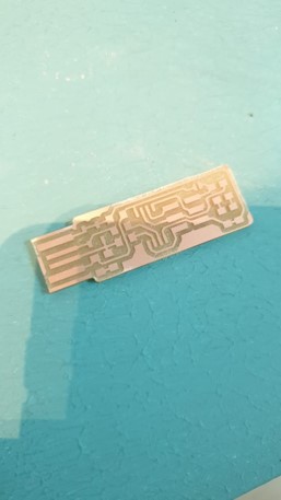
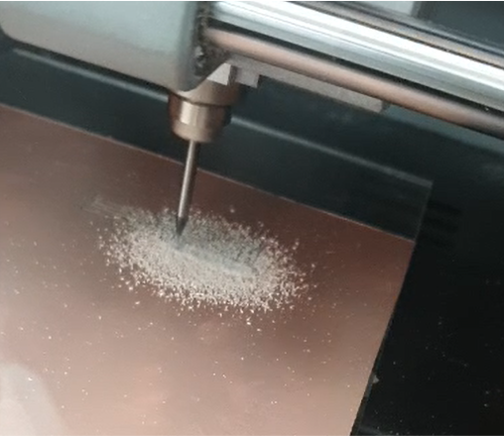
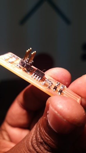
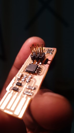
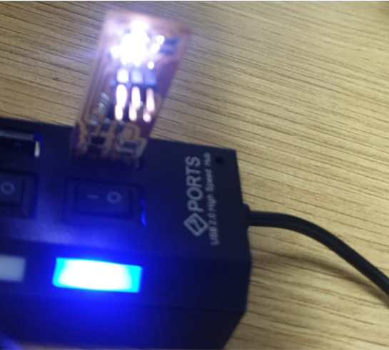
Step 11: fter soldering Take a Hero shot
problems
after finishing the solder i connected the fabtiny isp to the computer but the led was not functioning, it tourn out that i inverted the direction of the Anod and cathod
Test if the Led is ON
pluged it in the usp hub and the Led is on which means that every thing is ok now and ready to start programming it
Programming
To programm the programmer i followed this tutorial Using the GNU AVR toolchain on Windows 10 since my operation system is windows 10
Step 1: Download and install git
you can download git for windows from here (https://git-scm.com/download/win).
this step i have already done it before in Project Management week and made a Toturial on how to download and install git

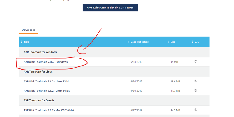
Step 2: Install the Atmel GNU Toolchain
Download the Atmel AVR Toolchain for Windows from Atmel’s site and run the installer. When asked where to extract the files, click the “…” button and navigate to C:\Program Files, then click Extract.
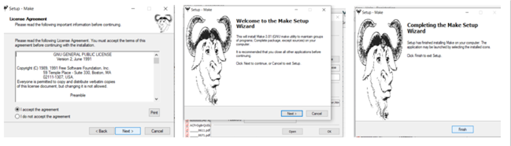
Step 3: Install GNU Make
Download Gnu Make and launch the installer. Accept the default location for the installation. You can choose whether or not you want an icon in your start menu.
Step 4: Install avrdude
Download avrdude . Unzip the archive, and copy the archive inside to C:\Program Files.
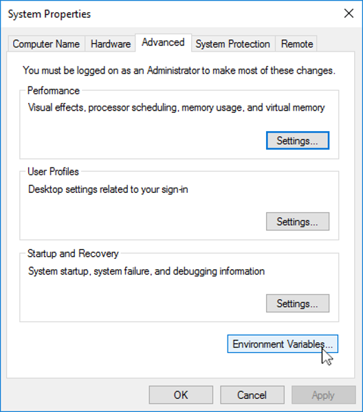
Step 5: Update your PATH
Now we need to tell Windows where to locate all of the tools you’ve just installed when you type their names on the command line. Go to the Start menu and open the Control Panel, then go to System. From the left pane, choose “Advanced System Settings”. Under the Advanced tab, click the “Environment Variables” button.
Under User variables, select “Path” and click the Edit button. If you don’t already have a variable called “Path”, click the New button to create it, enter “Path” without the name, and fill out the value as described below.
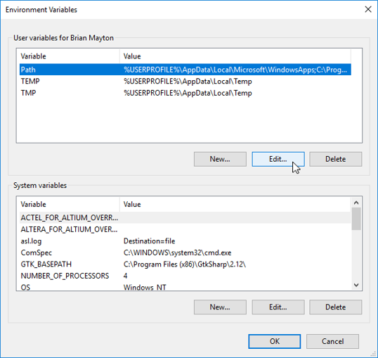
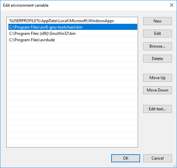
The Edit window that pops up is unfortunately different depending on whether you are creating a new variable or only have one item in your path, or if you have multiple items in your path already. In the first two cases, you just get a textbox for a value. In the third case, you get a list of values. Either way, you want to add the following three values. If you get the list, add them as separate items (see screenshot below). If you get the textbox, enter them separated by semicolons. Make sure that they are entered exactly or Windows won’t be able to find the programs.
The three values to add are:
- C:\Program Files\avr8-gnu-toolchain\bin
- C:\Program Files (x86)\GnuWin32\bin
- C:\Program Files\avrdude
Click OK on all of the windows you’ve opened.
Step 6: Install Drivers for your Programmer
This tutorial assumes you are going to use a FabISP, FabTinyStarISP, or other USBtiny-based programmer. If you are using one of the official Atmel programmers instead, the easiest way to get the drivers is to install Atmel Studio.
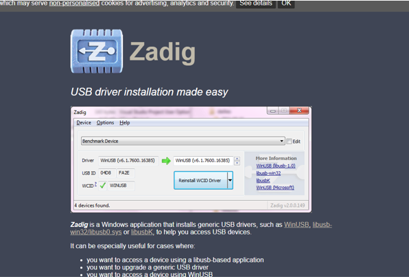
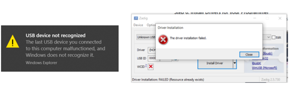
The USBtiny programmers use a generic libusb driver, but Windows 10’s driver signing policy makes the installation more complicated. Fortunately, there’s a tool that helps with this. Download Zadig and launch it. Plug in your programmer, and select the “USBtinySPI” device in the list. (If it doesn’t show up, go to the Options menu and click “List All Devices”. The driver you want to install (to the right of the green arrow) is either libusb-win32 or libusb0. Click the “Install Driver” button. You should only have to do this once.
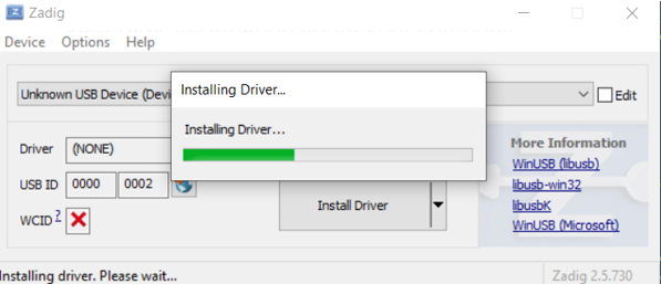
For me this step it didnt go well, USBtinySPI didnt show up from the drag down window evern when i clicked list all Devices
Step 7: Sanity Check.
Everything is now installed. Let’s check that it all works.
Go to the start menu and search for “Git Bash” and start it. When you see instructions telling you to open your terminal in other tutorials, this is the terminal window you should use.
Check to make sure that the commands we installed work okay:
make
Type make -v and press enter. You should see: GNU Make 3.81 Copyright (C) 2006 Free Software Foundation, Inc. … and so on.
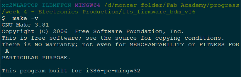
If you get a “command not found” error instead, re-check your installation of make and your path variable setting for typos.
avr-gcc
Type avr-gcc –version and press enter. You should see:
avr-gcc.exe (AVR_8_bit_GNU_Toolchain_3.5.4_1709) 4.9.2
… and so on.
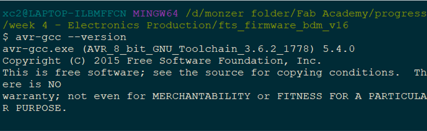
If you get a “command not found” error instead, re-check your installation of the Atmel toolchain and your path variable setting for typos.
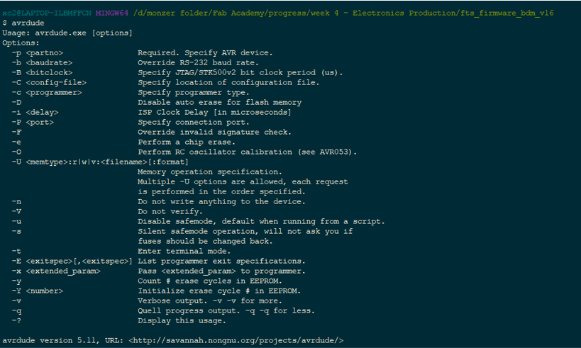
avrdude
Type avrdude To See if its installed in your system it sholud return the version of avrdude
avrdude usbtiny
Connect your programmer to a USB port and type: avrdude -c usbtiny -p t45 and press enter. You should see:
avrdude.exe: initialization failed, rc=-1 … This means that avrdude successfully found your programmer, but failed to talk to a target board (expected because we don’t have anything conencted to the programmer right now.)
If instead you see:
avrdude.exe: Error: Could not find USBtiny device (0x1781/0xc9f) check your USB driver installation (the Zadig steps).
If you get a “command not found” error, check your installation of avrdude and your path variable.
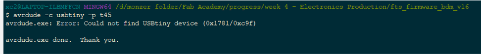
And this is what heppend with me its the step with Zadig Software, so instate of wasting time i decided to do it with arduino software
programming ATtiny45 With Arduino as isp
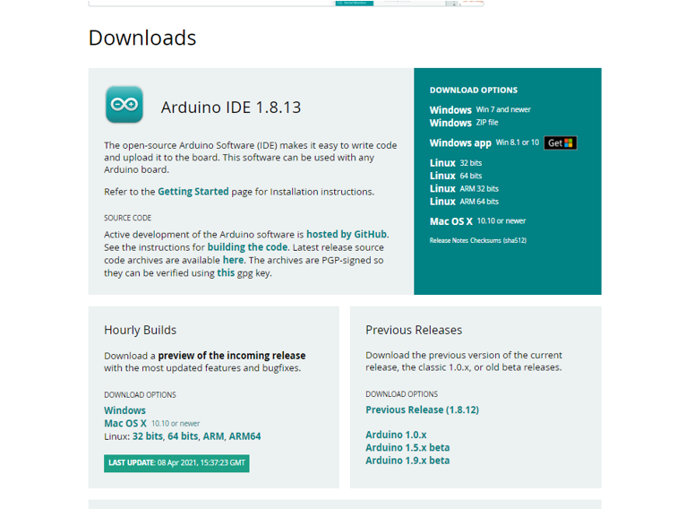
first you need to have Arduino ide you can download it from here depends on your operation system choose the one suitable with you
programming ATtiny45 With Arduino as isp
i foloowed this toturial to upload the sketch using
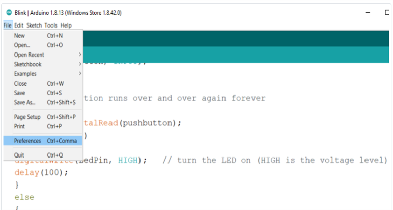
add attiny board
First you want to open File > Preferences.
Then, at the bottom of the pop up menu where you see “Additional Boards Manager URLs” you want to copy and paste “https://raw.githubusercontent.com/damellis/attiny/ide-1.6.x-boards-manager/package_damellis_attiny_index.json" (without the quotation marks).
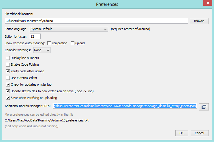
Now click OK.
Navigate to Tools > Board > Board Manager.
Scroll down to the bottom and you should find “attiny”. Click the install button and the words “Installed” should appear when the task is complete.
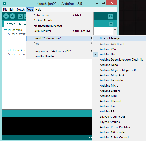
To confirm that you have added support for the boards, navigate to Tools > Board and you should see ATtiny at the bottom of the list.
Setup Arduino As ISP
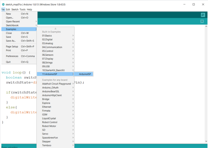
Navigate to File > Examples > ArduinoISP. Open the sketch and upload it to your Arduino.
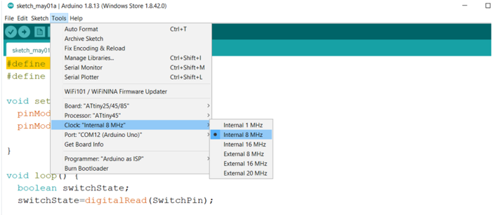
choose the board attiny microcontrollers attiny 25/45/85
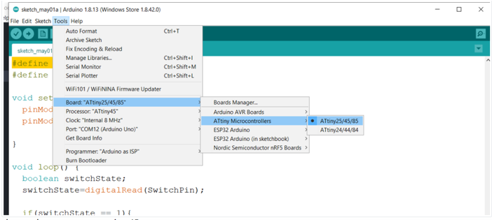
choose the processor to attiny 45
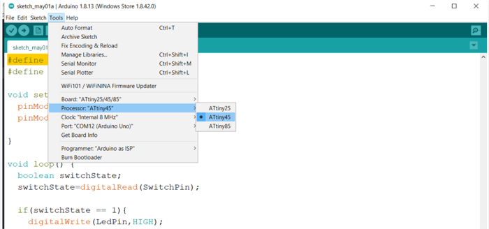
choose the internal clock 8 MHZ
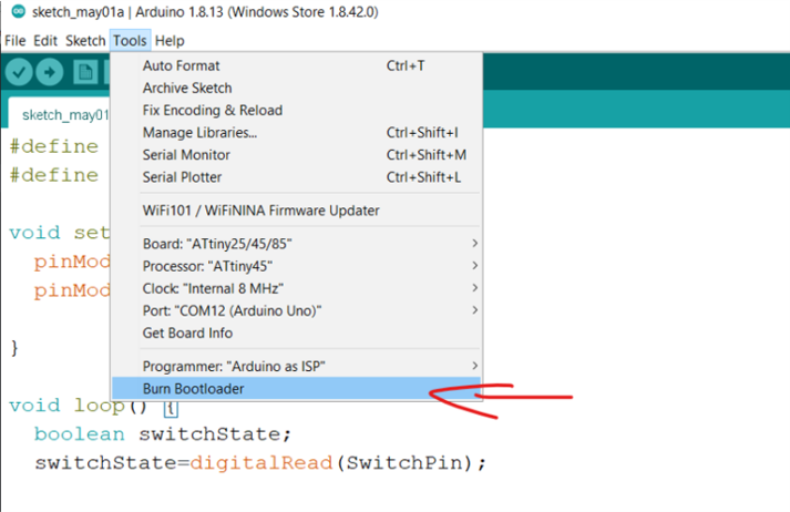
burn bootloader
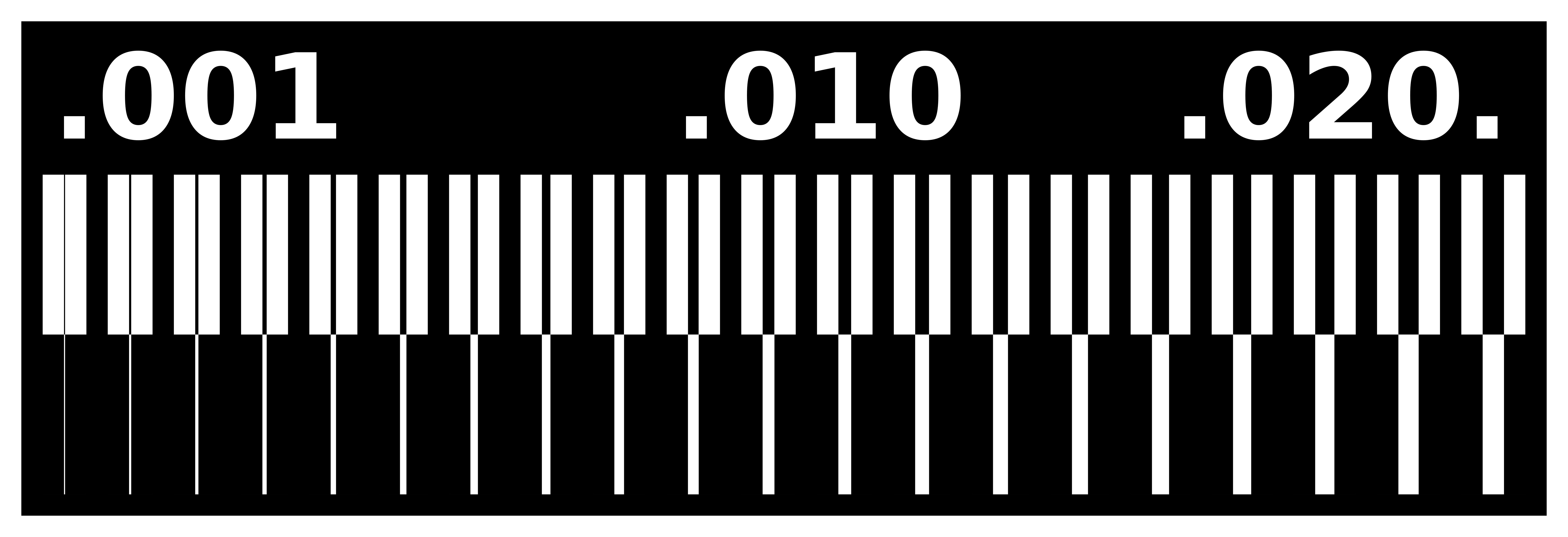
Download the files
- Teslines Traces
- Teslines Boarder
- Teslines SRM-20 rml file for Traces
- [Teslines SRM-20 rml file for Boarder](linetest.png (2).rml)
- FabIsp SRM-20 rml file for Traces
- FabIsp SRM-20 rml file for Boarder
Original tutorial by:
Champaign-Urbana Community Fab Lab By Xinao Wang, Dean, and Virginia McCreary | v1.0 | 10.2014
Updated by Xinao W on 5Oct2014.
Remixed/Updated by Eduardo Chamorro, Fab Lab Seoul 01.2017