 Erwin Kooi
13 - Embedded networking
Networking! The core of our data-driven society.
This is my week. Networks are my “thing” and I get to play with an idea that has been in my mind for more than 15 years…
- Group assignment:
- Send a message between two projects
- Individual assignment:
- design, build, and connect wired or wireless node(s) with network or bus addresses
- I have worked with I2C and SPI before.
- I want to work with the MPCM (Multi Processor Communication Mode) of the avr microcontrollers.
- MPCM is not so complicated, once you wrap your head around it.
- Interrupt-driven communication frees up your processor for its main task and allows for minimal code sizes.
- This has great possibilities for my final project.
Please check the group page for details on our collaborative work.
I could not stand that there was some weird behaviour in the host and client communication, so I recreated the setup at home (using four AtMega32u4’s).
Turns out that the used Serial.print() function converts the data to ASCII. So Serial.print(1) will send 0x31 (the ASCII representation of the character “1”). Using the Serial.write() function will send the data as it was meant to be sent. So Serial.write(1) will send 0x01.
The source code for the host can be found here.
The source code for the client can be found here.
For years this is something I wanted to try out…
For my final project multiple microcontrollers have to talk to each other.
The avr-series datasheet mentions a special hardware serial communication mode called MPCM (Multi Processor Communication Mode). The information is very sparse, but the idea sounds cool.
What you see in this movie will be described in the documentation below.
In the 500+ page AVR datasheets there is a tiny section that caught my eye:
From the datasheet:
Multiprocessor Communication
The Multiprocessor Communication mode (MPCM) effectively reduces the number of incoming frames that have to be handled by the receiver in a system with multiple microcontrollers communicating via the same serial bus. This mode is enabled by writing a ‘1’ to the MPCM bit in the Control B register (USARTn.CTRLB). In this mode, a dedicated bit in the frames is used to indicate whether the frame is an address or data frame type.
If the receiver is set up to receive frames that contain five to eight data bits, the first Stop bit is used to indicate the frame type. If the receiver is set up for frames with nine data bits, the ninth bit is used to indicate frame type. When the frame type bit is ‘1’, the frame contains an address. When the frame type bit is ‘0’, the frame is a data frame. If 5- to 8-bit character frames are used, the transmitter must be set to use two Stop bits, since the first Stop bit is used for indicating the frame type. If a particular slave MCU has been addressed, it will receive the following data frames as usual, while the other slave MCUs will ignore the frames until another address frame is received.Using Multiprocessor Communication
The following procedure should be used to exchange data in Multiprocessor Communication mode (MPCM):
- All slave MCUs are in Multiprocessor Communication mode.
- The master MCU sends an address frame, and all slaves receive and read this frame.
- Each slave MCU determines if it has been selected.
- The addressed MCU will disable MPCM and receive all data frames. The other slave MCUs will ignore the data frames.
- When the addressed MCU has received the last data frame, it must enable MPCM again and wait for a new address frame from the master.
The process then repeats from step 2.
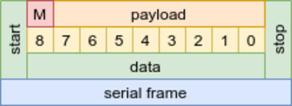 In MPCM mode, there are two types of frames. Address frames and data frames. They are distinguished by the value of the 9th bit (called "bit 8"). The AVR series has a mode where only a "1" in the 9th bit will generate a RX interrupt.
Basically the controller sends an address byte and flips the 9-th “this is an address” bit (versus a “this is data” ). All nodes receive this address, but only the node with the correct address will set its serial circuitry to active.
For years I wanted to play with this, but never had the right project for it. :-)
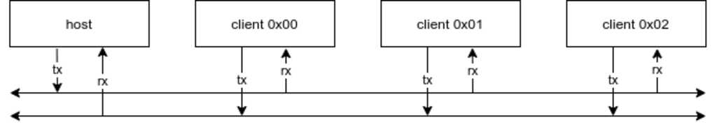
For this setup I will be using one atmega32u4 as controller and three atmega32u4 as clients. I had these in my electronics box.
All nodes need to communicate using 9 bits in a serial frame. The setting will be 9,n,1, or 9 bits, no parity, 1 stopbit. The default setting is 8,n,1 so only the frams size needs to be ajdusted. For the AtMega32u4, this means:
UBRR1   = 51;                       // 51 = 9600 baud, see datasheet for the calculation
UCSR1A |= (1<<MPCM1);               // Enable MPCM mode
UCSR1B |= (1<<RXEN1)|               // Enable the RX circuitry
          (1<<RXCIE1)|              // Enable the RX interrupt
          (1<<UCSZ12);              // Set frame size to 9
UCSR1C |= (1<<UCSZ11)|              // Set frame size to 9
          (1<<UCSZ10);              // Set frame size to 9
// There is more documentation in the source code files
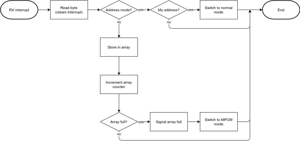
The clients will use interrupts to process incoming data. This will make sure that there is no blocking code for executing its main task.
Auto-generated flow charts
I found that the Geekdoc theme includes functionality for auto-generating flowcharts and sequence diagrams. This is done with the Mermaid framework.graph LR BEGIN([RX interrupt])-->A1[Read byte] A1-->Q1{MPCM mode?} Q1-- yes -->Q2{My address?} Q2-- yes -->A3[Switch to normal mode] A3-->END([END]) Q2-- no -->END Q1-- no -->A4[Store in array] A4-->A5[Increment array index] A5-->Q3{Array full?} Q3-- yes -->A6[Signal array full] A6-->A7[Switch to MPCM mode] A7-->END Q3-- no -->ENDgraph LR BEGIN([RX interrupt])-->A1[Read byte] A1-->Q1{MPCM mode?} Q1-- yes -->Q2{My address?} Q2-- yes -->A3[Switch to normal mode] A3-->END([END]) Q2-- no -->END Q1-- no -->A4[Store in array] A4-->A5[Increment array index] A5-->Q3{Array full?} Q3-- yes -->A6[Signal array full] A6-->A7[Switch to MPCM mode] A7-->END Q3-- no -->ENDI will be using this from now on…
The hardware serial of the AtMega32u4 is designated USART1 (to distinguish from the native serial USB connection), so all registers and pins are labeled TX1, RX1, USCR1A and so on.
The flow chart above is converted to code:
ISR(USART1_RX_vect) {
  unsigned char data = UDR1;                // Record the received byte from the buffer
  if ((UCSR1A & (1<<MPCM1)) == 1) {         // Use MPCM-bit to check if we are in MPCM mode
    if ((data == RX_UNICAST_ADDRESS) ||
        (data == RX_BROADCAST_ADDRESS)) {   // Our address or the broadcast address has been received
      UCSR1A &= ~(1<<MPCM1);                // Disable the MPCM mode to receive the data frame
    } else {
      ;                                     // Not our address, remain in MPCM mode
    }
  } else {
    if ((UCSR1A & ((1 << FE1) | (1 << DOR1))) == 0) { // No errors detected, store the byte in the buffer
      rxBuffer[rxBufferIndex] = data;
      rxBufferIndex++;
      if (rxBufferIndex >= FRAME_SIZE) {    // Complete frame received
        rxBufferIndex = FRAME_SIZE;         // Signal complete frame received
        UCSR1A |= (1<<MPCM1);               // Switch to MPCM mode
      }
    }
  }
}
// There is more documentation in the source code files
As you can see, the hardware of the USART of the client will ignore data frames as long as the client is in MPCM mode. This will greatly reduce the number of interrupts the client has to deal with if the data was meant for another client. Great!
int main(void) {
  // initialize stuff here
  sei();                                    // Enable global interrupts

  while(1) {
    if (rxBufferIndex == FRAME_SIZE) {      // A full array has been received
      switch (rxBuffer[0]) {                // Process the command byte
        case 0xAA:                          // The LED is addressed
          if (rxBuffer[1] == ON) {
            PORTB |= (1<<PB0);
          } else {
            PORTB &= ~(1<<PB0);
          }
          break;                            // **Never forget the break in a switch statement...**
        default:                            // No valid command byte received
          break;
      }
      // Done processing the frame, reset the index for the next frame
      rxBufferIndex = 0;
    }
  }
}
All nodes need to communicate using 9 bits in a serial frame. The setting will be 9,n,1, or 9 bits, no parity, 1 stopbit. The default setting is 8,n,1 so only the frams size needs to be ajdusted. For the AtMega32u4, this means:
UBRR1   = 51;                       // 51 = 9600 baud, see datasheet for the calculation
UCSR1B |= (1<<RXEN1)|               // Enable the RX circuitry
          (1<<RXCIE1)|              // Enable the RX interrupt
          (1<<UCSZ12);              // Set frame size to 9
UCSR1C |= (1<<UCSZ11)|              // Set frame size to 9
          (1<<UCSZ10);              // Set frame size to 9
// There is more documentation in the source code files
Warning
Note that the host does not have to switch to MPCM, since it will be the one determining if a frame is an address frame or a data frame.
The host will use interrupts to process outgoing data. This will make sure that there is no blocking code for executing its main task.
  graph LR
    BEGIN([TX interrupt])-->Q1{Did we send an address?}
    Q1-- yes -->END([END])
    Q1-- no -->Q2{Is there more data to send?}
      Q2-- yes -->A1[Increment array index]
        A1-->A2[Send next byte]
        A2-->END
      Q2-- no -->A3[Signal array empty]
      A3-->END
The flow chart above is converted to code:
ISR(USART1_TX_vect) {
  if ((UCSR1B & (1<<TXB81)) == 1) {         // Did we send an address?
    ;                                       // Yes, we sent an address, we are done
  } else {
    if (txBufferIndex < (FRAME_SIZE - 1)) { // No, we sent data. Send the next byte if available
      txBufferIndex++;
      UDR1 = txBuffer[txBufferIndex];
    } else {                                // No, we sent data. There are no more bytes to send
      txBufferIndex = FRAME_SIZE;           // Signal done sending
    }
  }
}
// There is more documentation in the source code files
The commands that are send by the host to the clients are in a loop
void txSendAddress(char Address) {
  while ((UCSR1A & (1<<UDRE1)) == 0);       // Wait till transmit buffer is ready
  UCSR1B |= (1<<TXB81);                     // Set the 9th bit to signal an address frame
  UDR1 = Address;                           // Send the byte (a completion of the send will generate a TX interrupt)
}

void txSendData() {
  while ((UCSR1A & (1<<UDRE1)) == 0);       // Wait till transmit buffer is ready
  UCSR1B &= ~(1<<TXB81);                    // Set the 9th bit to signal an address frame
  txBufferIndex = 0;                        // Start from the beginning of the frame
  UDR1 = txBuffer[txBufferIndex];           // Send the byte (a completion of the send will generate a TX interrupt)
}

int main(void) {
  // initialize stuff here
  sei();                                    // Enable global interrupts

  while(1) {
    txSendAddress(0x01);                    // Send client 0x01 address frame
                                            // Client 0x01 switched to normal mode
    txBuffer[FRAME_COMMAND] = COMMAND_LED;  // Set command byte to address the LED
    txBuffer[FRAME_DATA0] = ON;             // Set operation to ON
    txSendData();                           // Send the data frame
                                            // Client 0x01 switched to MPCM mode
    _delay_ms(1000);                        // Wait 1 second
    txSendAddress(0x01);                    // Send client 0x01 address frame
                                            // Client 0x01 switched to normal mode
    txBuffer[FRAME_COMMAND] = COMMAND_LED;  // Set command byte to address the LED
    txBuffer[FRAME_DATA0] = OFF;            // Set operation to OFF
    txSendData();                           // Send the data frame
                                            // Client 0x01 switched to MPCM mode
    _delay_ms(1000);                        // Wait 1 second
  }
}
// There is more documentation in the source code files
The protocol I will be using in the final project looks like this.
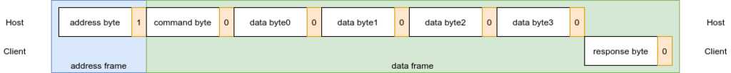
Parts of it can already be seen in the code snippets above.
A standardized protocols.h file will be used to make sure that all commands are the same for host and clients. This will allow for much more readable code.
#ifndef _PROTOCOL_H_
#define _PROTOCOL_H_

#define FRAME_COMMAND   0
#define FRAME_DATA0     1
#define FRAME_DATA1     2
#define FRAME_DATA2     3
#define FRAME_DATA3     4
#define FRAME_SIZE      5

#define COMMMAND_LED    0xAA

#define ON              1
#define OFF             0

#endif
- The host sends address 0x01 and instructs the client to switch its LED on.
- The host sends address 0x02 and instructs the client to switch its LED on.
- The host sends address 0x03 and instructs the client to switch its LED on.
- The host sends address 0xFF (broadcast) and instructs the clients to switch their LED off.
The source code for the host can be found here.
The source code for the client can be found here.
- The interrupt-driven way of dealing with serial communication works very well and results in low code sizes. The code sizes for the demo in the video are
- host: 640 bytes Flash and 6 bytes RAM
- client: 434 bytes Flash and 6 bytes RAM
- I used the older AtMega32u4 as I had plenty of those laying around. This does not impact the functioning of MPCM.
- Getting your head around the 9-bit frames was confusing. “Do I need to switch the host and client to 8-bit mode for transferring the data frame?” No, you do not. :-)
- Not much. I will continue to work on this protocol as it is also a fundamental part of my final project.