The first week where we get to fully focus on out final project. Most of the progress that I made on my final project during week 17, the creation of the wooden enclosure, is woven into my Final Project page. On this page I’ll answer the questions required for our weekly assignment.
Assignments
Our tasks for this week are:
- Propose a final project masterpiece that integrates the range of units covered, answering:
- What will it do?
- Who’s done what beforehand?
- What will you design?
- What materials and components will be used?
- Where will come from?
- How much will they cost?
- What parts and systems will be made?
- What processes will be used?
- What questions need to be answered?
- How will it be evaluated?
- Note | Your project should incorporate 2D and 3D design, additive and subtractive fabrication processes, electronics design and production, embedded microcontroller interfacing and programming, system integration and packaging.
My Masterpiece
Used in the more literal sense, to present my final project to show that I have “mastered” the techniques of the Fab Academy. I’ve created a Final Project page in which I take you through the entire design process and on which you can find elaborate answers to all of the questions that are posed above.
However, let me summarize my final project.
The Idea
For my final project I’m aiming to create:
A jigsaw puzzle where placing each piece correctly will spark a mini light show.
Many people enjoy the feeling of clicking / pushing each piece into a puzzle, me included. For my final project I want to make the act of puzzling and placing each piece correctly even more fun and exhilarating for any puzzle enthusiast.
I’m creating a “jigsaw puzzle box”, into which you can place puzzle pieces. Every time that you correctly place a piece, you’ll see a “light show” below the puzzle pieces already on the board. The further and further you get with the puzzle, the bigger the area of the light show becomes.
The Design
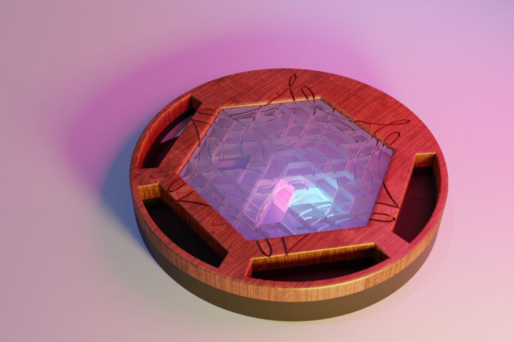
There would be a central area onto which you place the puzzle pieces. Since this will involve electronics, the “plate” onto which you’ll place the puzzle piece will be somewhat higher than the ground (to have the electronics and lights below it). I therefore wanted to “wrap” the whole in a wooden exterior to hide the electronics. I made the following render of my idea in week two of the Fab Academy. A lot has stayed roughly the same in looks, except that I’ve removed the cubby holes along the sides.
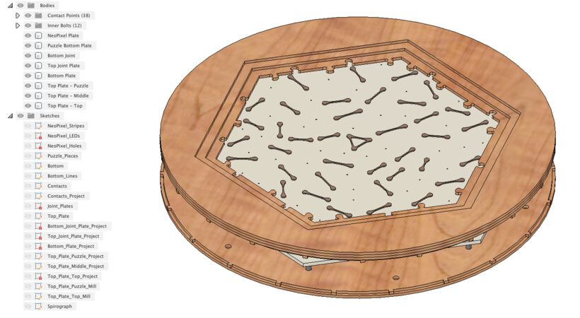
Below you can see the actual design of the final project that I built in Fusion 360. The only things missing from the image are the living hinge that wraps around the outside, and the puzzle pieces themselves (although you can see the “copper bridges” that are stuck to the bottom of each piece). Those two parts were designed in separate files/software.
I tried finding what other people have done that is similar to this in the Fab Academy search. However, it came up empty, I wasn’t able to find anybody that previously combined the idea of jigsaw puzzles and light. I kind of like that though (*≧▽≦) it means that I’m not biased at all by earlier designs, that I have nothing to live up to, and I can really see this as something that I’ll have built myself (well, my partner, and Henk, helped a lot with being my brainstorming partner on how to handle some of the more practical things of putting it all together.)
Searching for “light jigsaw puzzle” more generally on the web even came up empty. I only found puzzles about the aurora, and a specific type of lamp called “IQ Light Jigsaw Lamp”, which has nothing to do with my project. This LED Jigsaw Puzzle Light probably came the closest, but it’s still far off from my idea. It uses etched acrylic with a light source from the side of the puzzle to show a pattern. However I want to be able to control the lights individually below each piece, so the light will need to come from the bottom, instead of one fixed light along the sides. I also found this Tetris Lamp where each Tetris piece is a light source, which light up when stacked together. Although a cool idea, these tetris blocks are much bigger than what I intend my puzzle pieces to be, and they only emit one color of light.
Questions
For a long time I had no idea how to do the electronics. Should each puzzle piece get its own LED? Would it be embedded within the puzzle piece, or be placed below the board? How would I sense if a puzzle piece was placed? Should each puzzle piece get its own ID? If yes, what technique should I use?
At the start I got the advice to use RFID chips inside the puzzle pieces, with a/many scanner(s) below the puzzle plate to register when a piece was placed. However, after asking some experts in electronics they generally told me that this probably wouldn’t work; RFID chips aren’t meant to be used with many bunched up at the same area, you’ll probably get interference. In the “Input Devices” week I realized that I could instead turn each puzzle piece into a simple “bridge” that, when placed, would close a switch that I could detect.
I eventually also realized that it would be better to have the lights below the puzzle, and not inside each puzzle piece. It would become too complex otherwise, since I wanted ±50 puzzle pieces, and each piece had to be unique. In the “Output Devices” week I turned a 5 meter long strip of NeoPixels into a hexagonal grid to use as my light source.
Another tricky part was how to create the top plate without showing any bolts or screws on the outside. Thankfully, my partner showed me inserts that you can screw into wood and that have thread on the inside. I could place those in the bottom of the top plate(s) and have a bolt running from the bottom plate to the top plate to hold the full puzzle box together.
Creation Process
In order of actual creation, this how the parts were made:
- I used a laser cutter to cut out the hexagonal plate onto which I placed the grid of NeoPixels. I cut the 5 meter strip of NeoPixels into smaller strips and, stripped, cut and soldered them all together again in a hexagonal grid.
![]()
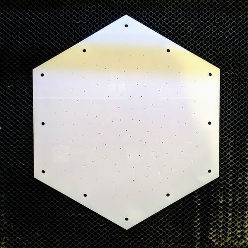
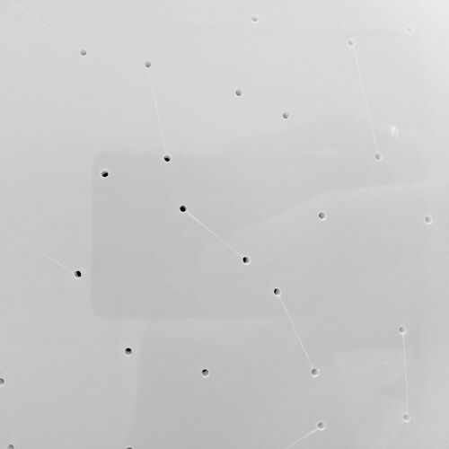
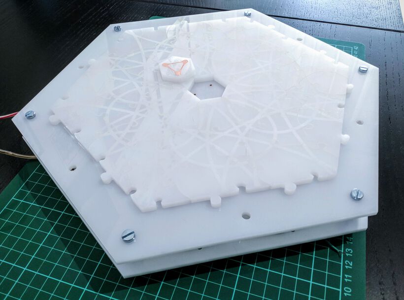
- I laser cut the hexagonal plate onto which the puzzle pieces get placed. There are 114 tiny holes in this plate into which I placed 1.0mm copper rivets, 76 of which were soldered to a wire to act as switches, one for each puzzle piece.
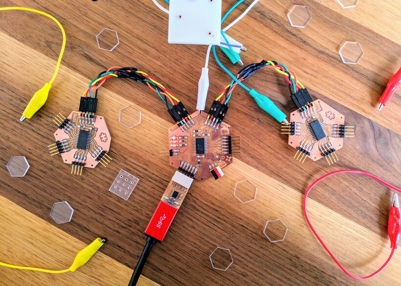
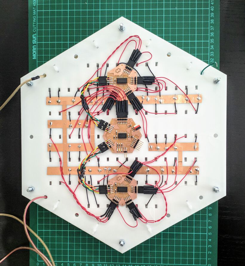
- I used a small milling machine to mill out three small PCBs. Wires run from the bottom puzzle plate to 38 pins on these PCBs so I can check which puzzle pieces have been placed.
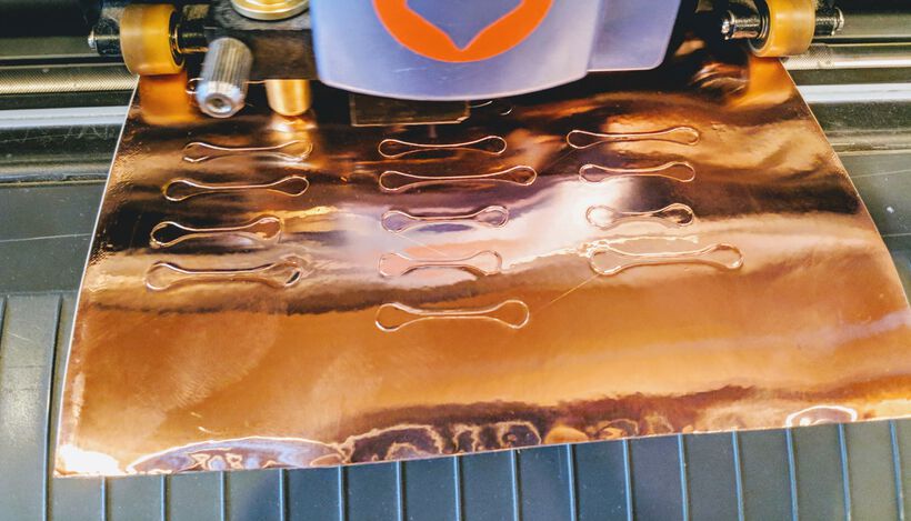
- I used the vinyl cutter to cut out the copper contact bridges that get placed on the bottom of each puzzle piece.
- I used the laser cutter to cut out my puzzle pieces and etch out a spirograph design on top.
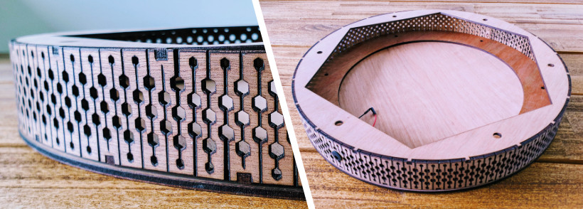
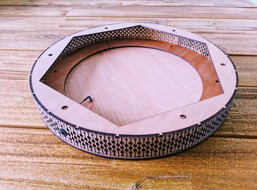
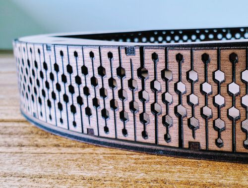
- I used the laser cutter to create the living hinge pattern from wood that wraps around the internal section of acrylic, along with the two wooden plates the fit into the joints along the living hinge.
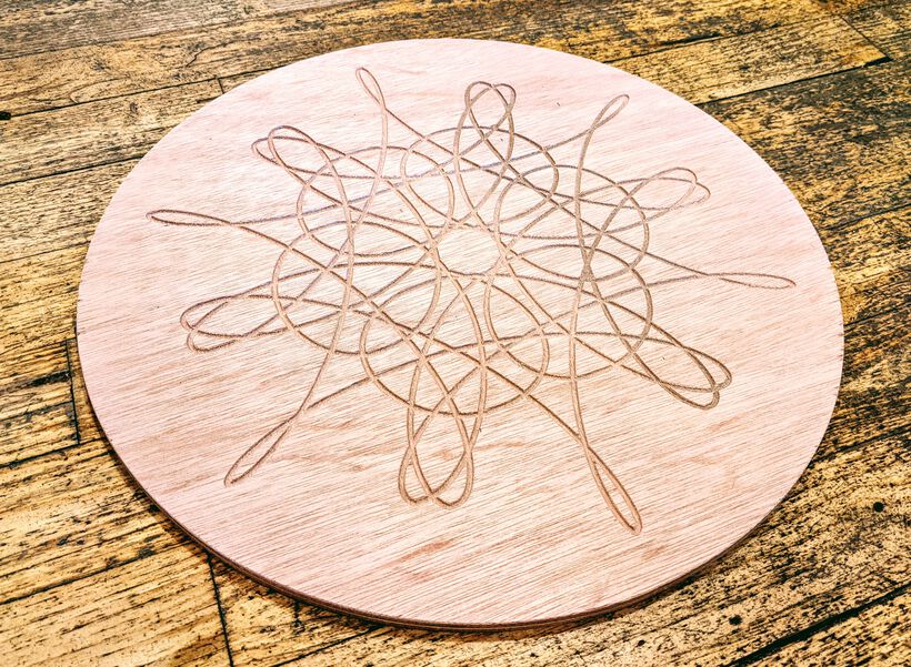
- I used the CNC milling machine for the bottom plate. This kind of came about unexpectedly, because I was trying to create the top plate. However, the 1mm milling bits kept breaking as I tried to mill out the puzzle piece shapes. I was therefore left with a nice circle and etched out spirograph, which would make a great thick bottom plate.
- I used the laser cutter to create the top layers. I initially tried using the CNC milling machine to mill out the puzzle piece ears using a 1mm milling bit. It kept breaking however. I therefore decided to use three layers of 3mm wood that could be laser cut instead.

I’ve designed everything in Fusion 360, except for the PCBs, which I designed in KiCad, and the puzzle pieces, which I designed in Affinity Designer (on my iPad Pro).
Materials
In terms of electronics I’m using mostly standard parts, all soldered to PCBs with wires running between them. I’m using an ATtiny3126 as the main microcontroller, and two PCA9555D multiplexers to get 32 more GPIO pins. Another big part are the 217 NeoPixels that create the light show below the puzzle pieces. All these materials were supplied by the Fab Lab.
I’ve used nice hardwood multiplex for the exterior of the puzzle enclosure. The puzzle pieces themselves need to let through light, but not be transparent (otherwise you’ll see the copper bridge that is taped to the bottom), and are thus created with opal acrylic. With the NeoPixels being placed below the bottom plate of on which the puzzle pieces are placed, this bottom plate also needed to let light through, but not be transparent, and thus also became opal acrylic. For the plate on which I fixed the NeoPixels I also chose to go with acrylic, because I needed a really straight plate, but also something that the NeoPixels strip would remain stuck to even if the LEDs/material gets warm, which I was afraid wouldn’t happen well enough for a wooden plate.
The acrylic and 3mm multiplex were supplied by the Fab Lab, whereas I bought the 9mm multiplex myself. I also purchased all the nuts and bolts that keep it all together as well as the 2.1mm plugs and 5V 8A adapter.
If you’re interested in knowing each specific materials that I’ve used, how much it all costs, and where they can be bought, you can find it in the Bill of Materials.
Evaluation
In the most general sense I see my final project as a success if people will have a fun time putting the puzzle together. Even better if they find it even more special than putting together a normal cardboard puzzle.
From my personal perfectionist side and the importance that I put on how something “looks”, I also want my project to look beautiful. No “acrylic box” around some internal electronics. Instead, the way every part looks (especially if it’s visible from the outside) will be as important to me as how the electronics will work internally.
From a technical side, my final project will be a success if it manages to create a light show beneath all the puzzle pieces already on the board, to change its light show when a new puzzle piece is placed, and that no LEDs beneath empty places turn on, or LEDs beneath already placed pieces turn off or flicker.
Wrapping up
Only two weeks left! I’m happy that I seem to be quite far/almost finished with the “physical” side of my final project. Hopefully the programming of the NeoPixels and the contact points on the puzzles will be successful!