
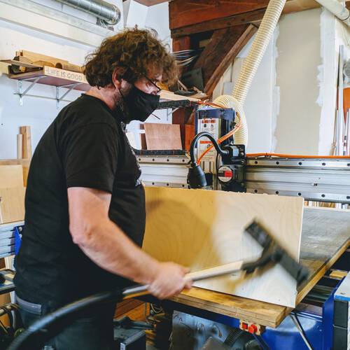
This week we had to “make something BIG” on the CNC milling machine. We had access to a wooden sheet of 250x122cm, which was even bigger than I imagined. This being a dangerous machine we didn’t have the luxury to experiment as we did with the laser cutter and 3D printer, so we had to keep our design relatively simple.
Assignments
Our tasks for this week are:
- Group assignment:
- Do your lab’s safety training
- Test runout, alignment, speeds, feeds, materials, and toolpaths for your machine
- Individual assignment: Make (design+mill+assemble) Something BIG (~meter-scale)
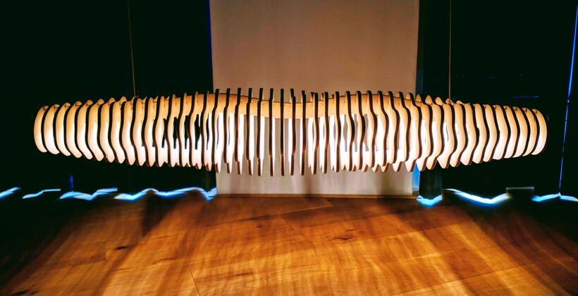
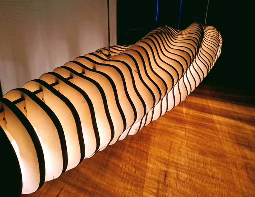
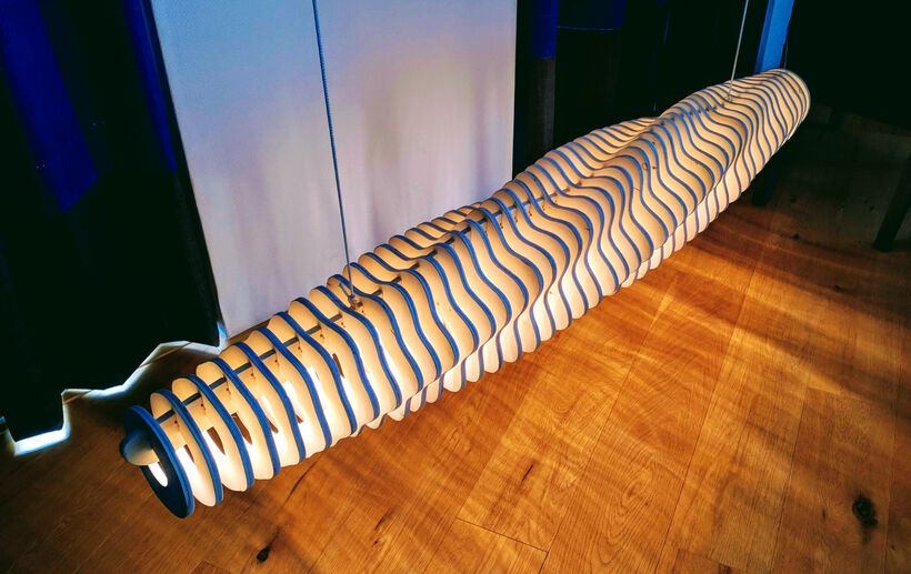
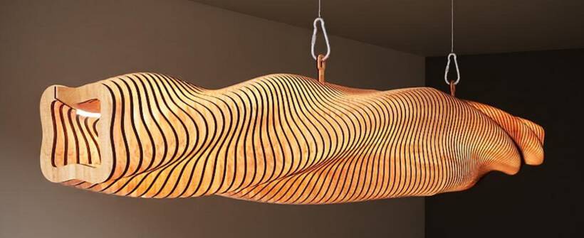
Hero Shots
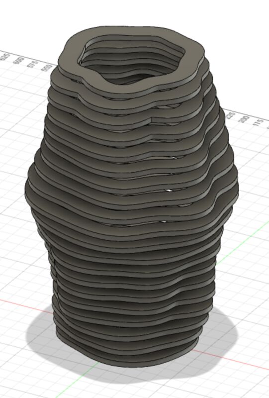
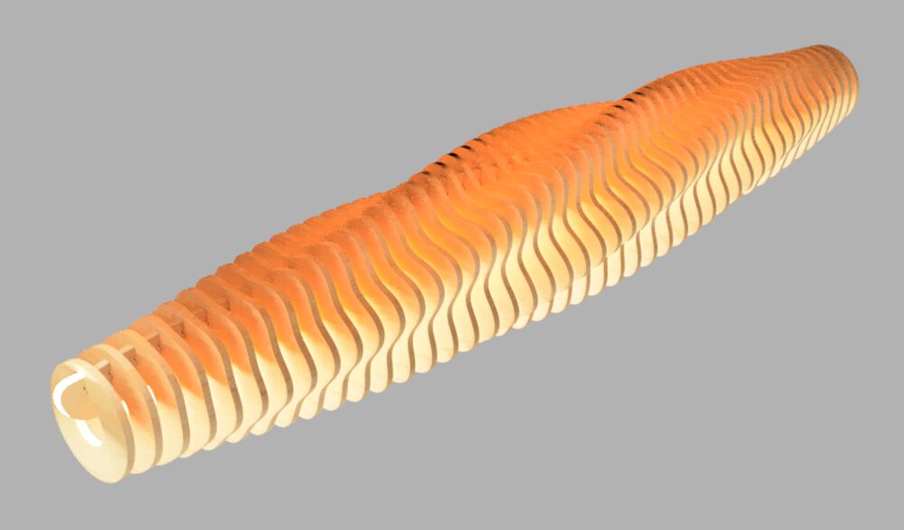
Showing some final results of the 150cm long ceiling light that I created for the tl;dr and hopefully showing you why the rest of this very long blog could be interesting to read (⌐■_■)
Design
For a very long time I had no idea what I wanted to make for this week. I generally like creating small things ( ^∇^) At first I thought about creating a big 3D globe with the relief of the lands and oceans milled out. However, I learned from Henk that we weren’t creating 3D shapes, but that it was more like the 2D of the lasercutter.
Inspiration
I therefore started gathering images of items that seemed possible with a CNC mill and created a Pinterest board to have them all in one overview. I considered a laptop stand for sitting on the couch for a while, lots of lampshades and tables, but most were quite intricate in their design, with many parts having to fit together. And Henk asked us to create something simple, because there was no room to experiment as we had at the laser cutter.
I also looked at the (now discontinued) Fusion 360 Slicer software for a bit, which seemed really cool. I saw that this very interesting table was created with it. And this and this video showed some really interesting designs.
And then I came across this ceiling light and I thought “Bloody hell, that’s gorgeous!”.
In essence this wasn’t a complex constructions. Many slices that have to fit in one spine. I’d been thinking of making new lights for our dining table. I showed the image to my partner and he found it quite nice as well. So it was decided, I wanted to create my own version of this lamp.
The way I wanted my lamp to be different was to have it be more of an elongated ellipse, not a tube. I also wanted to use Perlin noise to create the patterns flowing through the lamp from one side to the other.
Fusion 360 with the Python API
I wasn’t quite sure what tool I should use to create my idea with. It was recommended to use Fusion 360, but I didn’t know how to create shapes based on mathematical functions or noise. Basically the same issue that I had with the 3D printing week, when I decided to go for Blender.
I searched for “creating natural shapes with Fusion 360” and came across a blog post on Instructables that showed how to create a really interesting shape using the python API with Fusion 360. Wait, Fusion has APIs?? That was interesting! Even though I’m a newbie at python, (I’m an R-lover instead), I figured that the perlin noise shape that I was looking for shouldn’t be too hard to figure out with python, there being some form of perlin noise library existing no doubt.
Within Fusion 360, you can run a script by going to the Tools tab, then clicking the Add-Ins button and selecting Scripts and Add-Ins… from the menu. Or, a much quicker way, by pressing SHFT+S. This will open up a window in which you can select which script (or Add-in) to run. If you click the little green “plus” sign under My Scripts you can add an existing script. By clicking on the Create button at the bottom will pop-up another window asking what to create, in what language (python or C++), the name of the scripts and where to save it.
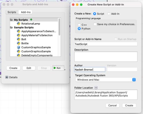
Creating a new script will create a new folder within the one you specified with the name of the script. Within that folder there is a dummy python script with the basic structure of setting up a script for Fusion 360, and a manifest file with some metadata.
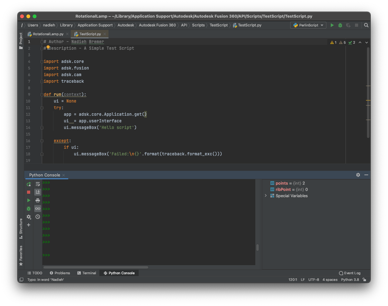
I installed PyCharm as a GUI to hopefully work with python, knowing how happy I am with the RStudio GUI that I always use with R. I’m definitely not used to PyCharm yet. I wish they hadn’t mapped the ⌘+Enter short key to 10 other things, so I could use it to run my script line-by-line as I’m used to with RStudio. Instead, I have to use ⌥+SHFT+E.
You have to set-up a configuration to be used to run a python script, which comes down to choosing which version of python you want to use. I feel like I’m not understanding something there probably, because to me it isn’t clear why you also need to define exactly what script to run per configuration, and not just choose one python version and use that same configuration to run whatever script with.
Fusion 360 has its own specific library with all the API functions called adsk. I tried to somehow be able to load this library within PyCharm, so I could perhaps so some debugging, but I wasn’t able to get it working sadly.
The GitHub containing the files of that first blog that got me onto the Fusion 360 python API were really helpful in setting up a first simple example. But I also watched a short tutorial video about getting started with the Fusion 360 API. There was also a more advanced video which I eventually never took the time for to watch (*^▽^*)ゞ . In hindsight, maybe I should’ve and saved myself hours of googling on how to do things with the Fusion API later…
I started with an example to create some simple splines in a sketch, just to see if I could actually run a script (and I’d need splines for my perlin noise shape), which thankfully went smooth.
The one thing that was annoying, but understandable, was that I had to delete whatever the previous script had created. Because running the script again, would create another new sketch, and draw the splines in there. To not end up with hundreds of sketches and shapes that slow down Fusion, I always manually removed whatever the previous script had created. There are definitely ways to make the script take an existing sketch and work with existing shapes, but since I was changing so much, especially at this starting point, that was just not an effective tactic.
There is a big list of example scripts on the Fusion 360 website that was invaluable for me throughout the creation process. Such as making an extrusion from a sketch, or creating an offset based on a shape within a sketch.
You can even use user parameters with some of the functions, such as the extrusion (but not the offset strangely enough), using a statement such as:
distance = adsk.core.ValueInput.createByString("material_thickness")
Meaning that, once the script has run, and you change the parameter back in Fusion, the objects that were originally created with the script will update accordingly.
It was very hard to debug the code though ಠ_ಠ
You do get an error message pop-up that hints at the line where something went wrong. But figuring out the values of variables used within the script, that was something I never managed to figure out. Sure, I could create my own message box and have it output the variable, but typically that only resulting in some garbled text along the lines of object [object]. I was thus basically trying to debug throughout this whole week while mostly blind.
But getting back to the design side. Using a standard random function for now, I created wobbly circles, and with that multi-spline script I had used at the start, I could easily create more wobbly circles.
Now that I had a bunch of wobbly circles, it was time to use perlin noise to offset a circle instead of using a random function. I installed the noise function, and added it to my import statements, but that failed. Fusion 360 was apparently using its own install of python, and up till that point I’d only be using base functions.
I saw that most people created a Modules folder within the folder that contained their python script, would copy the module from their standard python library into that folder, and could call that module with Fusion 360 using from .Modules import noise. But that didn’t work for me.
I eventually found this answer on the Fusion 360 forum that adds the path of the project folder of my Fusion 360 python script to the path that Fusion will use to search for modules. But that also didn’t work for me. To make sure that it wasn’t the noise library specifically, I tried the same thing with the same example library that was used in the forum post, svgwrite, and that one did work.
Ok, so there was something with the noise library specifically. Looking closer at the error messages. They were about not being able to read _perlin and _simplex. I looked at the noise folder again, and noticed that there were two files with those names, but they had a lot of extra metadata in their file name as well: _perlin.cpython-38-darwin.so. On a whim, I changed the name to _perlin.so and _simplex.so and it worked! (ノ◕ヮ◕)ノ*:・゚✧
I don’t know why my general python install doesn’t mind those original names, and the Fusion version of python does (it has version 3.7.6 btw, whereas my standard python install is 3.8), but I didn’t care, and moved on to incorporate the perlin noise into my wobbly circles.
I looked up some blog posts about the perlin noise function, and watched the always brilliant Dan Schiffman from the Coding Train’s video about symmetric perlin noise to set up my own version of slowly changing wobbly lines.
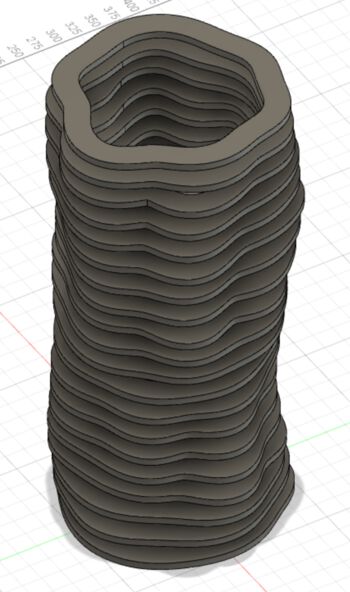
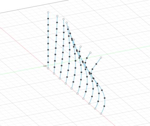
I then added a function that altered the radius of each slice from smaller to big in the center and then back again. I used a quadratic easing on this, so the radius change is faster at the outer edges. Here is a whole collection of easing functions to use. And then applied the perlin noise on top of that (image below right)
I flipped the slices on their sides, so it would be more in line with the idea of it hanging along our dining table (and not running upwards vertically). I also found a good post on extruding multiple profiles from one sketch in one go. That way there’s only one extrusion in the history at the bottom, instead of one per extrusion, speeding things up.
I played some more with the settings of the perlin noise function to have a shape that was changing fast enough, but not too fast. I increased the number of slices to almost 60, because I wanted this light to be about 150cm long.
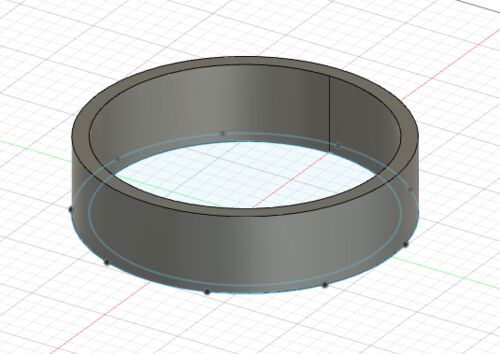
I did have some issues with the offset because Fusion couldn’t calculate them for each shape. I think it has something to do with the creating of loops at some inner corners? I therefore deactivated the offset for a bit, so I could at least see the general shape of seeing all the slices at once:
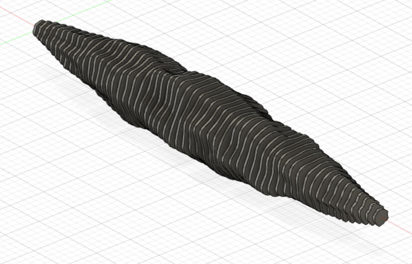
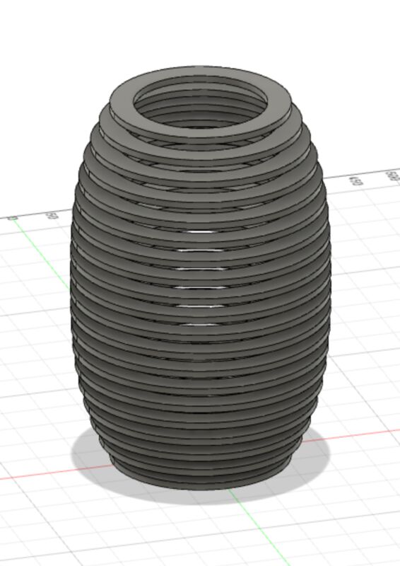
And….. I did not like it enough ಥ_ಥ I found it to be interesting, but when I compared it to my initial inspiration lamp, I liked that one more than my version. So, even after hours of making this design work with perlin noise, I deleted those parts from my script and decided to stick closer to the idea that the inspiration lamp was using: rotating a shape while increasing its size (and back again).
That lamp used a squarish form, but it only reminded me of a rotating sandwich. I wanted to go for a hexagon as my base shape naturally (⌐■_■)
In terms of the math I didn’t create an actual hexagon, but a circle with a cosine shaped offset to the radius that would run around the circle six times:
# Calculating the spline points
loops = 6
steps = 8 * 6
amplitude = 1.35
for i in range(steps):
    p = (i / steps) * math.pi * 2

    offset = math.cos((i % loops) / loops * math.pi * 2) * amplitude

    x = (radius + offset) * math.cos(p)
    y = (radius + offset) * math.sin(p)
I added a “dampening” factor to the cosine offset, so it would have no impact at the outer edges, creating a standard circle, and then go to full impact in the middle. I also added a rotation of the cosine (this comes down to adding an internal phase) to create that flow along the lamp which is what I liked the most about the original version
I was still having problem with creating an offset on my splines, even with such seemingly easy shapes. Searching for solutions, I found a post that recommended to extrude the spline as a surface, and then thicken it instead.
I found some example code on how to extrude surfaces and thicken them. It did work, but I couldn’t make the shape very thick. Anything above ±13mm and I would get errors. I think this was again something to do with the thickened shape creating self crossing loops?
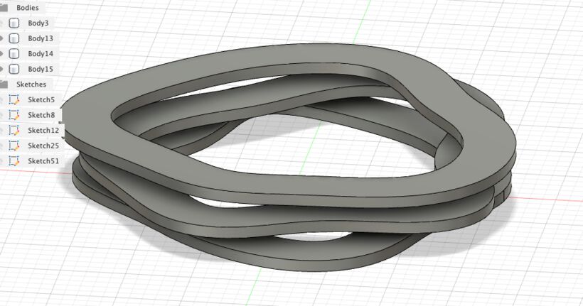
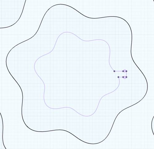
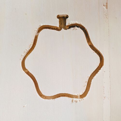
And so, I figured, if I can calculate a hexagon shape at radius x I can also calculate the same spline at radius x+c. No need for offsets or thickening, I just created two splines myself and extruded the area in between. And that worked like a charm!
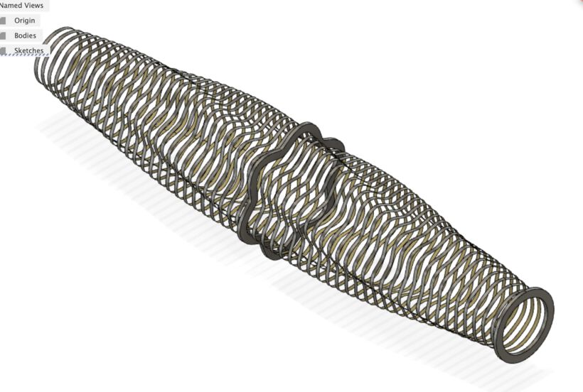
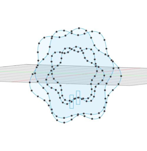
To connect all these slices together, I also needed a spine to hang them in. Thankfully, I could simply save all the 0th points of the splines per slice, and then finally create a sketch on a the yz plane (instead of the xz plane that the slices were on) that connected all those 0th points:
Arrange
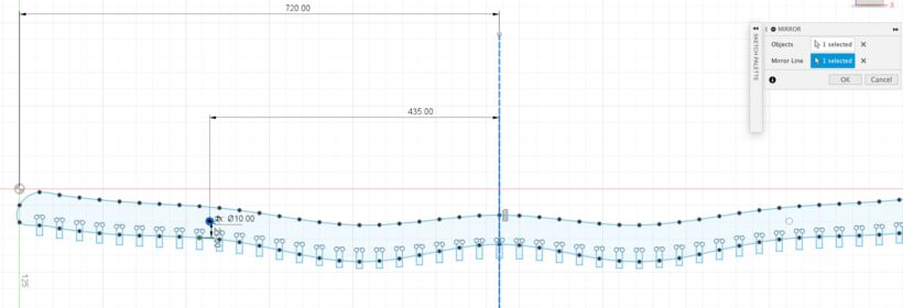
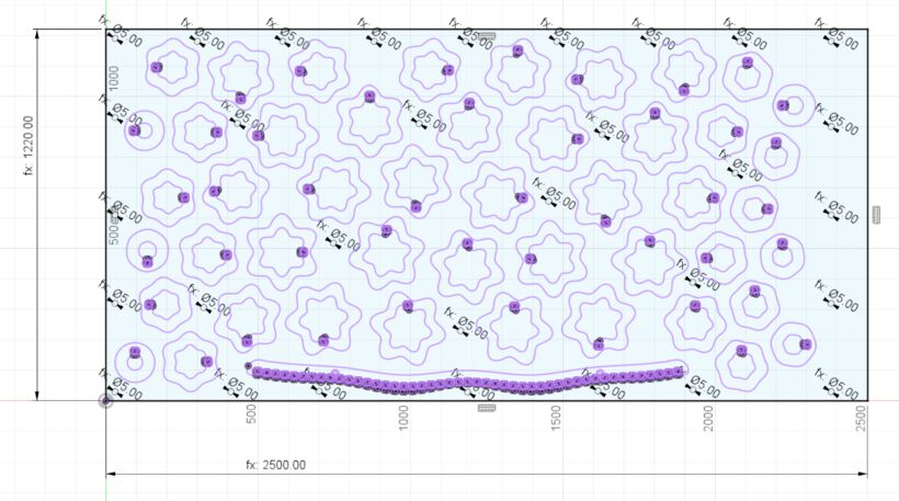
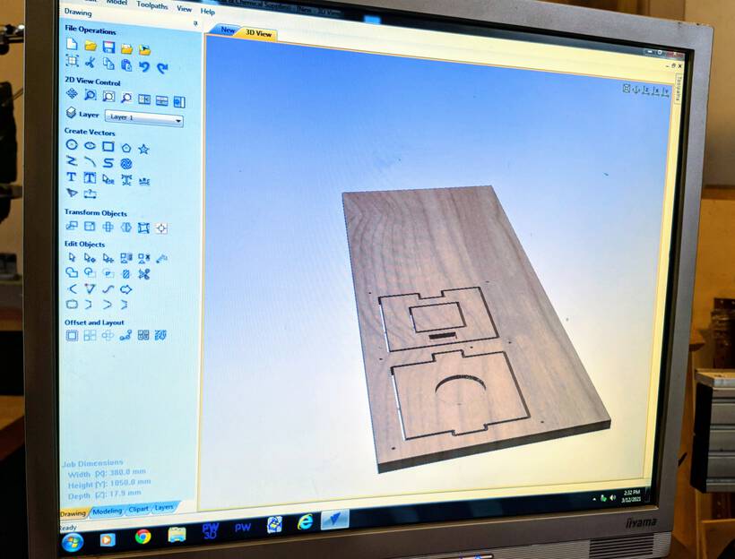
At this point I felt it was time to see if all of my ±60 blobby shapes would even remotely fit on the 2440x1220mm wooden plate that we could use (at first we were told the board was 244cm long, but it turned out to be 250cm).
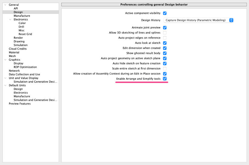
Fusion 360 has a handy Arrange feature, and right now we apparently have access to an advanced version of it, because it’s in preview mode (but it will become an expensive extension in the future I believe). However, the arrange option needs to be activated.
Open up the Preferences and in Preview Features check Advanced Arrange (if it’s no longer there, that means that the preview period is over). Next, in the Design tab, check the Enable Arrange and Simplify Tools.
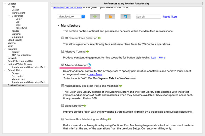
This page on the Fusion 360 site explains how to use the Advanced Arrange feature. But I also found this video and this video on the advanced functions to be really helpful.
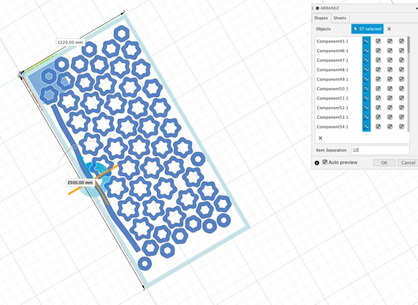
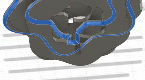
To be able to use the arrange option all my slices and spine need to change from being bodies to components. To do this, select all the bodies, right-click and select Create Components from Bodies. Next, still within the Design environment (you don’t necessarily need to go to the Manufacturing environment), click on the Modify tab (this falls under the Solid tab) and click on Arrange.
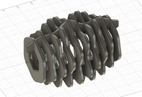
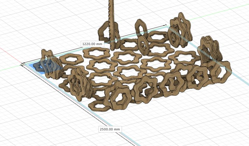
A window pops up from the side in which the first Shapes tab lets you select the shapes that you want to arrange. I had some weird things happen if I just drag-selected across all of the shapes, with some of them being arranged while on their sides (see image below right). But I found that if I tediously click on each component name in the Browser to the left it would always work.
I think I could’ve also made it work if all of the added shapes have that first icon to the right of their name in the arrange selection box activated (tht the icon is blue). It’s important to set the item separation to be big enough for the milling bit + some extra spacing to make sure the board doesn’t fall apart during the milling process. I eventually used 30mm so 20mm would be left in between each shape on minimum after the milling bit had run its course.
In the second tab, Sheets, you set-up the size of the material that can be used. With the non-advanced arrange, you need to create a sketch, and on that sketch have a rectangle that represents the sheet, which you can select here. However, with the advanced arrange you can also select Plane. This lets you select any plane (generally just unhide the Origin in the Browser tab and select the xy plane), and next you can set the x and y dimensions. The Sheet margin is the distance between sheets, which I didn’t have (I had one giant sheet), and I set the Border Spacing to 30mm in the end as well, which is the distance between any shape and the edges of the sheet.
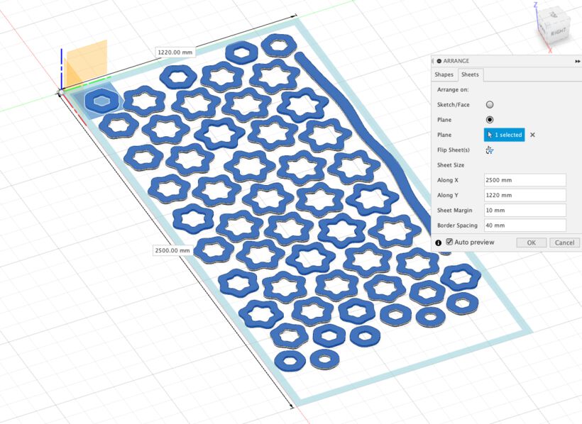
It will then start to arrange all the pieces on the board as a preview. Any shapes that don’t fit will be shown outside of the area, but I was in luck, and all of my shapes fitted! Barely though. If you press Ok you shapes will have moved to these new positions, so be sure to have the arrange only come after you’ve finished the design.
Tip | If you find that the arrange takes a really long time to run, then deactivate the Auto Preview, otherwise you’ll be waiting ages with each little change that you make ಠ_ಠ
Slots & Fillets
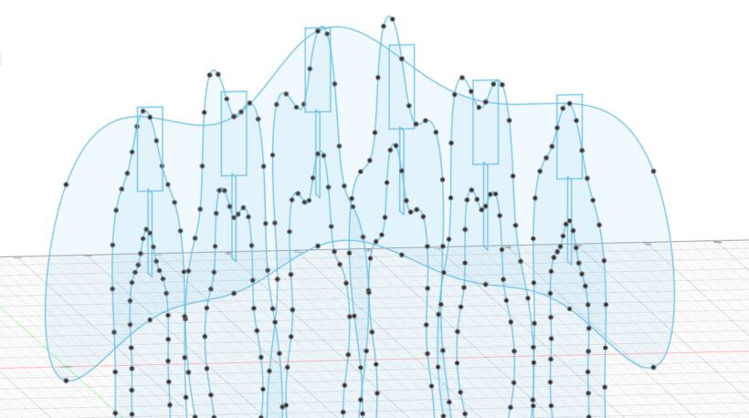
To make the slices and spine actually fit together, I had to create some slots in both of them. I therefore added some rectangles along the point of the 0th array position of each spline
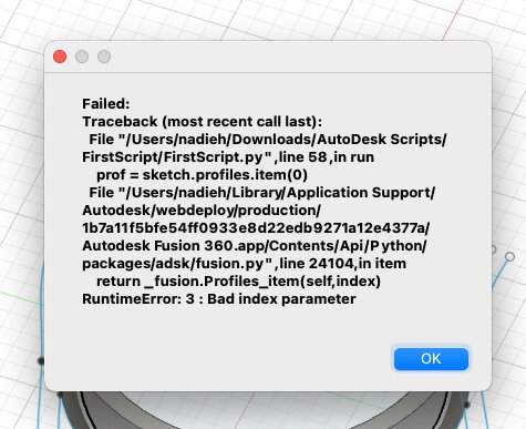
Adding these rectangles meant that there were a few more possible profiles in the sketch that could be used for extrusion, so I had to manually go through each profile index with python to see if the right one would be extruded in Fusion, and then figure out the system behind it, to use for each slice.
With the help of two examples I could also create a fillet along the outer edges of each slot. Here it took a little more time to figure out the pattern in exactly which number of possible fillets would create the two that I was looking for since there were quite a few edges by now
I repeated the same process for the spine, where I added rectangles along the top for each slot, and added fillets for each of the hard edges. This being the most complex shape of all, it took quite some time to figure out the exact patterns used to get exactly the extrusion and fillets that I needed.
Looking at the sketches of the slices and the spine helped to to assess that the slots fitted together perfectly.
Eventually I removed the fillets though, because I figured I’d be rounded the edges anyway during the sanding, and it was making the python script very slow.
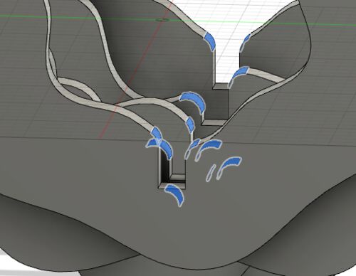
Dogbones & T-bones
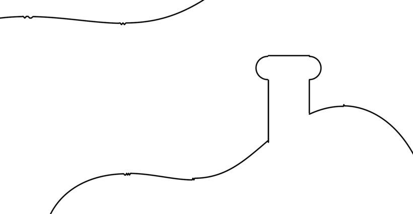
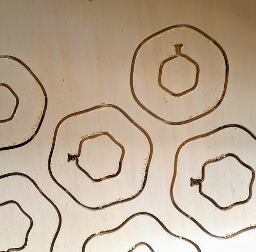
This being a job for a CNC mill, which has a round milling bit, we have to create so-called dogbones or T-bones in any corner where something has to slot or fit. And that’s because the round milling bit can’t create sharp corners.
Therefore, a little extra of the material needs to be milled away to make a good fit. For dogbones you basically have a circle with the same diameter as the milling bit centered on the corners of each slot’s right angle, whereas for t-bones this circle is moved up so the bottom of the circle aligns with the bottom of the slot (t-bones can be pointed to the sides, but also downward):
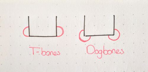
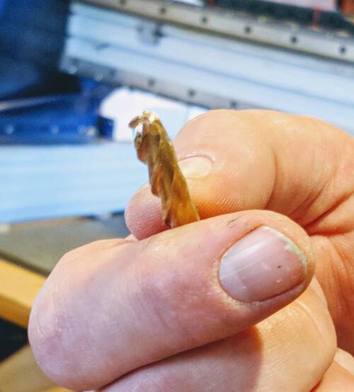
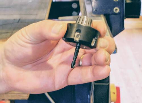
Our milling bit had a diameter of 5mm, and my wooden plank was 9mm thick. I could therefore actually not even use dogbones in my design, because there would be nothing left of the original bottom of my slot! I therefore needed t-bones with the circles pointing to the sides (image above left).
I first tried to use a dogbone add-in the was recommended by a fellow students. But I couldn’t quite get the add-in to work properly on my shapes, it kept on giving errors. Furthermore, I had about 55 slices at that time, which would be 55 * 4 = 220 dogbones to manually place, and I was still often running my python script to create the slices from scratch. It therefore made more sense to me to create my own t-bones.
The process was pretty simple. I added two tiny circles to each slice’s sketch (and along the spine, two per slot). I then only had to figure out the pattern to extrude exactly the right shapes yet again because of course the exact profile numbers had changed with the addition of the circles, both for the extrusion and the fillets.
And that was everything that I creating with the python script. In the end it took 17 minutes (!) to run, so doing a quick update to see the result wasn’t really an option. I therefore generally used about 8 slices to test new parts, and then hoped that I’d figured out the correct patterns to apply to any number of slices (sometimes the patterns seemed to change for a different number of slices sadly…)
- The final Fusion 360 python script | python file
The one thing I didn’t do via a python script was to include two holes along the spine that I would use to hang the lamp to the ceiling. I wasn’t willing to figure out how this would change the extrusion pattern yet again. Plus, it was very quick to do. In the spine sketch, I added a 1cm circle, placed this 45cm from the middle of the spine, around the center of the spin, and then mirrored it along the center of the spine, which I finally extruded as cuts from the spine.
Ok, and I also moved the two most outer points of the spine inward a little to create a more nicely rounded shape, but that was it in terms of manual creation of the final design ^.~
Exporting a DXF
I needed to export a .dxf file with the result from the Arrange for VCarve to read next and turn the lines into toolpaths for the ShopBot CNC Milling machine. I used this video to teach me how simple the process is.
Either select an existing sketch, or create a new sketch and the go to Create -> Project / Include -> Project. Rotate the sketch so you see the bottom side. Next, click on each face that needs to be projected into the sketch. Be sure to select the face as a whole, and not the edge of a face, or the side of the component.
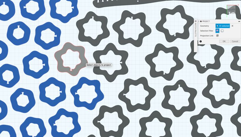
Afterwards click Ok, and now you’ll have new lines on the sketch that represent all the components that were projected. I found it easier to then hide the components. You can now finish the sketch and then on the sketch in the Browser right-click and select Export to DXF.
For my final sketch I also added a rectangle to the sketch that was the dimension of my sheet, just to make sure that the origin would be in the right location when loaded the file into Illustrator or VCarve. I also added circles at the places that I wanted the drill holes to be, making each have the diameter of the milling bit (the sacrificial layer was 244cm long, while the wood was 250cm long, so that’s why the drilling holes along the right are not at the edge of the board.)
- The final result from Fusion 360 | dxf file
Final Fusion Design
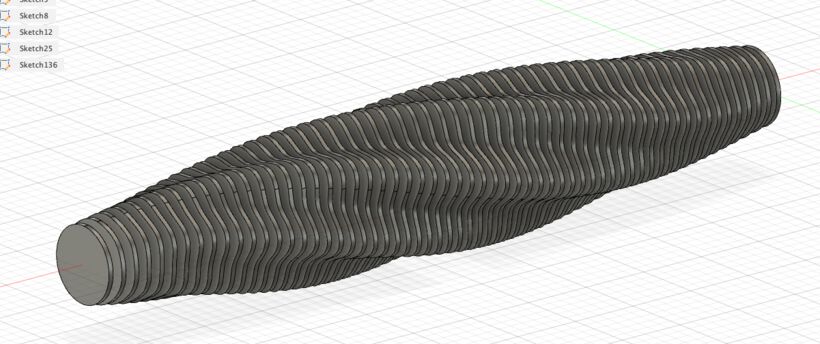
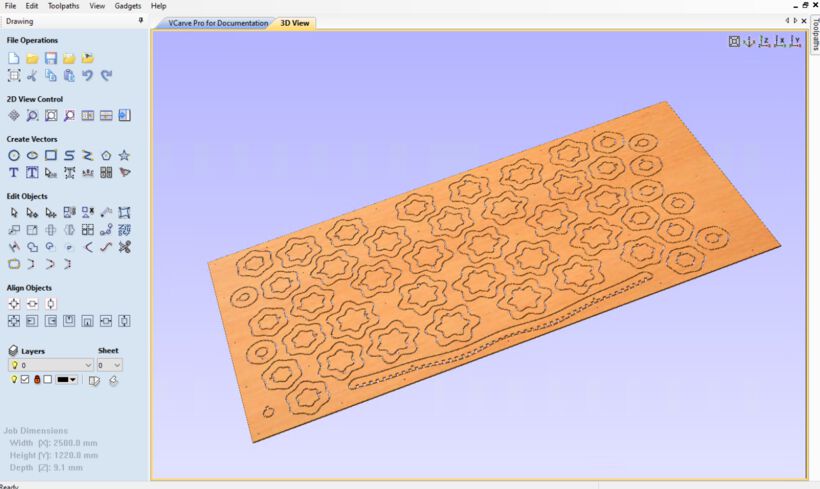
Below is the final assembled version of my design in Fusion 360. I decided to go for 47 slices, each spaced 3cm apart, because I was afraid that I’d run out of milling time on the machine. All those slices would make the lamp 150cm long, which was long enough really.
Timing
Even though these 47 slices and spine would fit on the board, I wasn’t sure if it would mill them all out in the time slot I had. With 8 students at the Waag, each of us had 4 hours to mill our design. However, that included everything, from cleaning the bed, placing it, doing the screws, etc. So the effective milling time was closer to two hours, maybe three if you were really efficient.
I therefore made a “back of the napkin” calculation. On average, say that I have 47 circles to mill out, both an outside and an inside. And the largest circle had an outside of about 125mm max radius and an inside of about 85mm max. I knew that the blobby shape would make the outline bigger, but I figured that would easily be offset by the fact that the slices could be much smaller than 125mm on the outsides. Using the formula for the circumference of a circle (2 * π * R) I would thus need to mill 47 * 2 * π * (125 + 85) = 62,000 mm, plus a spine that was about 2 * 1500mm in its circumference, adding in total to 63,500 mm of distance to mill.
At the instruction day at the Waag I got the sense that the machine did about 50mm a second. It could thus do 50mm * 3600 = 180,000mm an hour. However, the milling bit would only cut out 2.5mm for each pass, so I would need 4 passes to fully mill out a shape from my 9mm board. Effectively the machine could thus completely cut out about 180,000 / 4 = 45,000 mm/h. So the rough 63,500 mm that I expected to need would take about 1h20m. Well, that seemed very reasonable!
(Trying to) Clean Up the Design in Illustrator
This will come in the next section, but VCarve, the tool we had to use to go from vector design to CNC milling toolpaths, doesn’t like to calculate milling paths around vectors that aren’t connected into one full shape. And generally any sketch that you export from Fusion 360, especially if it’s the result of a projection, has separated vectors at each bend and corner.
Strangely, you can’t join lines inside sketches with Fusion 360 . Truly, if it wasn’t for that one tiny thing, I think I could’ve skipped having to export to Illustrator as an in-between step.
At first, when I loaded the .dxf file into Illustrator, it was very tiny. Only on my second attempt at loading the file did I pay closer attention to the import options. At the Scale option I had to set 1 pixel equal to 1 mm if I used the scale option. Or use the Original Size option, but then be sure that the document that you’re loading it into is set to millimeters (you can see/change this in File -> Document Setup)
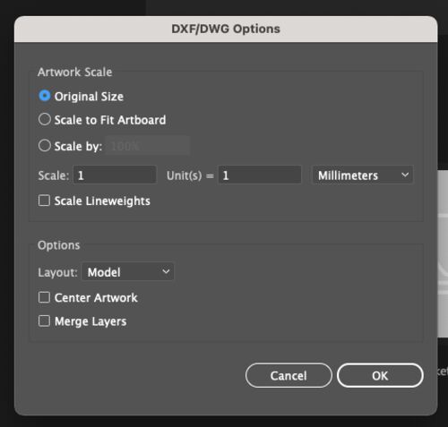
The most fail-proof way to correctly load the file into Illustrator, was to create a new file. Set the units to millimeters and set the artboard to the size of my wooden board (2500x1220mm). Next, go to File -> Place, select the .dxf file, and be sure to check the import options check mark. This gives you the same window as the image above. Adjust it to what I had above. You can then place the contents of the .dxf file wherever you want on the artboard in Illustrator, but the top-left corner makes it align perfectly with the artboard.
Having placed my .dxf file into Illustrator, it seemingly looked good from a distance. However, when I zoomed in, I saw that all of my shapes had weird jagged sections (●__●)
I tried looking for answers online, but I came up surprisingly empty. I only found one mention that I wasn’t sure related to my case, but about Fusion 360 being able to do splines of order 5, while Adobe could only process them to an order 3?
I wasn’t able to find a solution sadly, so I decided to go straight from the .dxf file to VCarve and close my vectors there. But just note, you can join vectors in Illustrator by selecting them all and pressing ⌘+J (or going to Object -> Path -> Join).
PS | I also imported the .dxf file into InkScape and there it didn’t even show the curved outlines! So I gave up on that very quickly, having no more time left to debug at that time.

Toolpaths
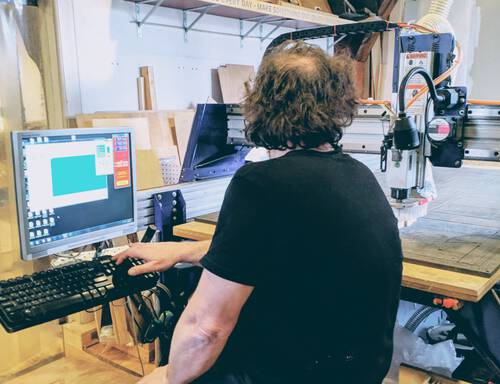
As we’ve seen in previous weeks, you generally need some tool to go from a vector or image file to toolpaths that the actual machine can use; the literal path that the head of the machine needs to follow. This has been the case for literally each big(ish) machine till now: LightBurn for the laser cutter, mods for the vinyl cutter and small milling machine (for PCBs), and PrusaSlicer or Cura for 3D printers. For the ShopBot at the Waag we use the VCarve Pro - ShopBot Edition.
We weren’t allowed to look into doing CAM within Fusion 360 this week, because Henk didn’t want us experimenting too much. However, this video by the Aalto FabLab shows the CAM process within Fusion 360.
Vcarve Pro
Open VCarve and select Create a new file. This will change the window to one where you can set-up the size and thickness of the material to mill. When you change the width and height numbers, the white rectangle will update (in ratio) accordingly.
Although the size of the width and height don’t need to be precise up to the millimeter, for the thickness it needs to be very precise. You should therefore use a caliper to measure the thickness of the material around the edges and try and find a good average value.
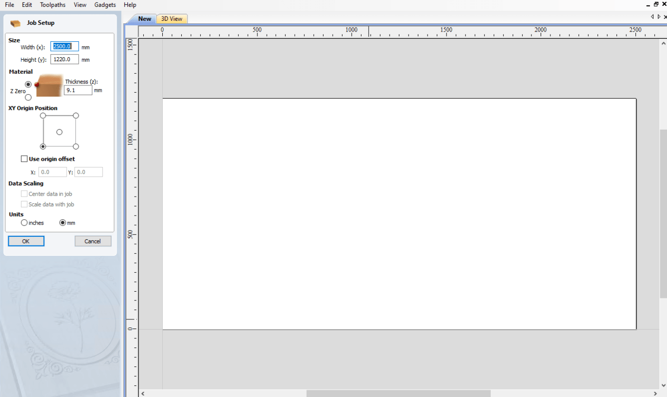
Set the Z Zero at the top of the material. For the ShopBot at the Waag the home point is in the bottom-left corner, and we use millimeters of course, not inches. When you’re done, press OK. You can always go back to this window by going to Edit -> Job Size and Position
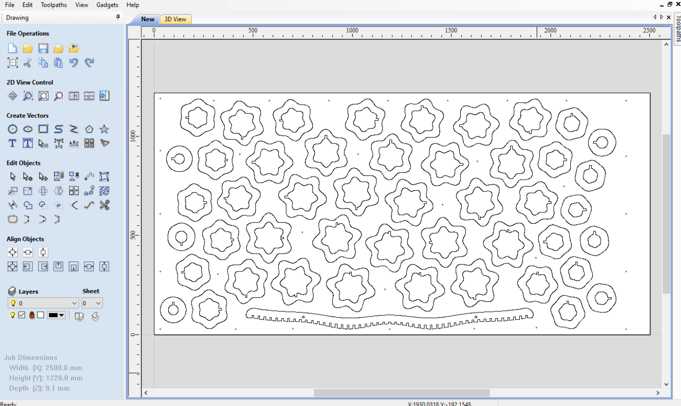
The options to the left will now have changed to a whole array of drawing icons, reminiscent of an old version of Illustrator.
Go to File -> Import -> Import Vectors and load the .dxf file with the design (or another vector file, such as .eps or .pdf).
Closing Vectors
As I mentioned in a previous section, VCarve doesn’t want to calculate good milling paths around vectors that it considers to be open. It will flat out tell you it can’t after you’ve painstakingly selected all the paths and set up the toolpath settings. So best to close all the vectors at the start.
Thankfully, this is (generally) very easy, because there are several “close vector”-like buttons in the drawing panel. However, there’s something sneaky in VCarve that I wasn’t aware of which didn’t allow me to close the vectors at first. VCarve doesn’t close vectors that are part of the same group. Why not? I don’t know. How do you know what’s part of a group? I also don’t know. But a general way to get around this is to click on the mouse-pointer icon and drag-click to select every path in the window. Next, click on Ungroup objects back onto their original layers (learned from this video).
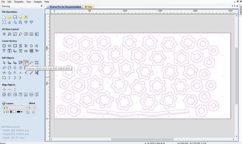
Now finally VCarve lets us close all vectors. With all of the shapes still selected, click on the Join Open Vectors button (the rounded rectangle line with five yellow circles on the line), which will update the drawing tab to show the number of open and closed vectors that it’s found, what tolerance to use to close vectors, as in, if vectors are closer than the tolerance, they will be closed, and how many open vectors remain after clicking Join.
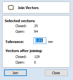
As you can see, this closed all open vectors for my design thankfully.
Adding Dogbones & T-bones
An essential part of any design with parts that need to fit together created with a CNC mill, is dogbones and t-bones. I’ve already discussed these in a section above about Fusion 360, because I created my t-bones there. However, VCarve also has a handy function to add these to any corner.
Within the Drawing panel, select the Select Fillets icon (it would’ve helped if either the word “dogbone” or “t-bone” was added to this, because in my mind fillets are something different). The drawing window will then update to let you choose the type of fillet to create.
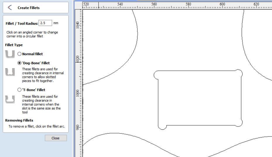
Be sure to set the Tool Radius (not the diameter) to the milling bit that you’ll use, which was 2.5mm for us.
You can click any corner where you want to create a dog/t-bone and it’ll appear. Click again to remove it. In the image above I made a dummy rectangle to show the result of some t-bones on the left (where you can choose which side the t-bone should be added) or dogbones along the right side.
But as I said, I’d already made my t-bones, so I didn’t go through this process in VCarve.
Types of Toolpaths
Each different type of toolpath will need its own set-up process. Click on the arrow icon along the middle-left of the drawing icons, and SHFT-click to select all the outlines that need to milled in the same way: drill holes, pockets, insides, outsides, etc.
Next, click in the top-right on the tiny Toolpath tab and select what type of toolpath to create (or what you else you might want to do with the selection).
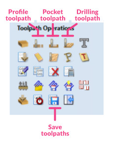
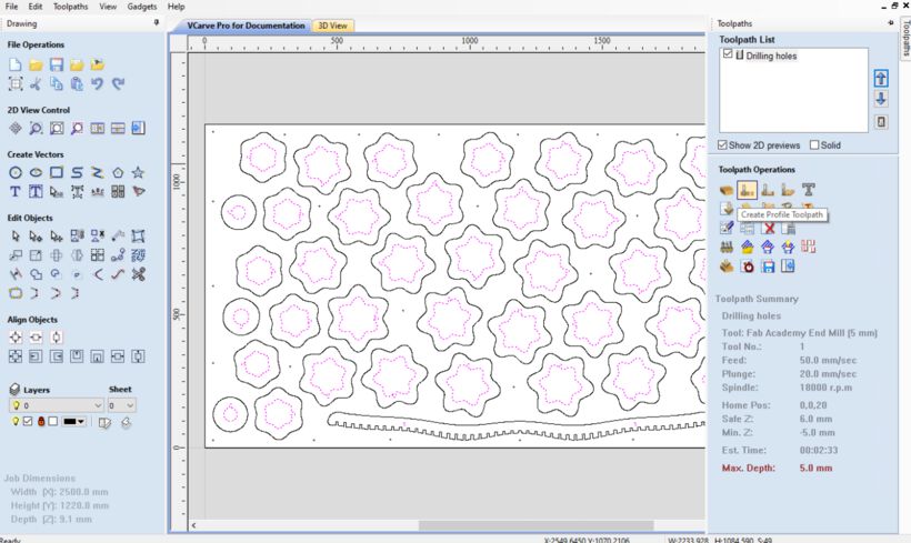
Drill Toolpaths
Drill holes are very useful to mark the places on the board which you can then place screws to fasten the wooden board to the machine bed (and then afterwards mill the actual design).
Having selected all the drill holes from the design, click on the Toolpath tab and next click on the Create Drilling Toolpaths icon.
This will switch the toolpath window to the options to set for these drill holes. You’re really only creating these drill holes to mark the board, so they shouldn’t go fully through the board. I set them to 5mm in Cut Depth.
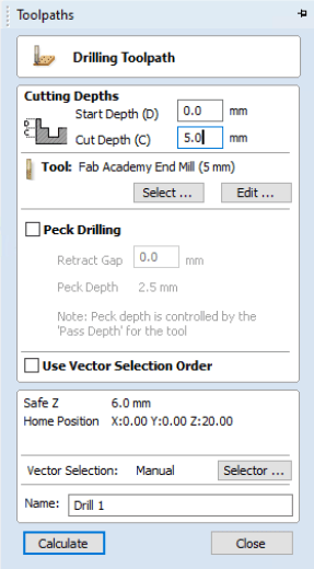
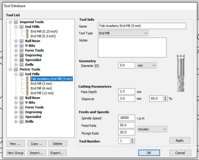
Under Tool you need to set the milling bit that you want to use. For more complex jobs, you might want to use different bits. Such as one to quickly remove the rough outline, and then another to do the fine finishing. For the (one) milling bit we’d use this week, Henk had set it up as follows:
The Peck Drilling can stay unchecked, same for Use Vector Selection Order. You can finally give this toolpath a descriptive name, to be able to recognize it later when we need to select exactly which toolpaths to mill in which order.
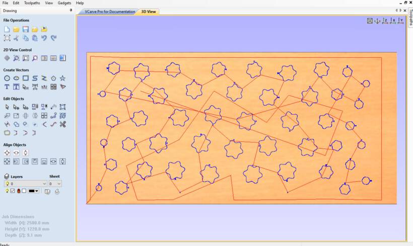
Finally, press Calculate. This will create the 3D View tab in which you can see the resulting toolpath that VCarve has calculated. With blue lines being milled paths, and red lines being movement of the milling head above the material. For the drill holes you really only see the red travel lines.
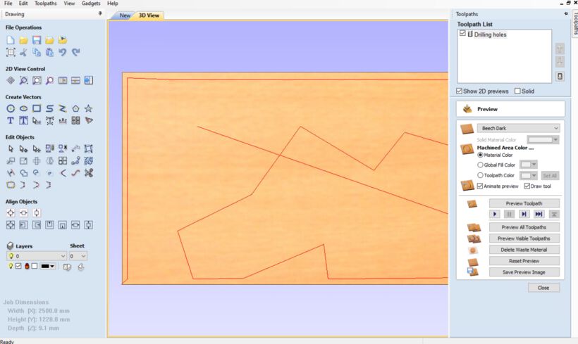
You can animate the toolpath to check if it looks ok (although it goes really fast), but generally just press Close, otherwise you can’t get back to the toolpath window with all the options. Click on the New tab (next to the 3D View tab) to go back to selecting new shapes for making into toolpaths.
Pocket Toolpaths
You can also create pockets, sections of the wood that are milled away to a very specific depth, but not all the way through. I didn’t have any pockets in my design, but just to show the selection options I selected a random inner shape, clicked on the Toolpath tab, and selected Create Pocket Toolpath.
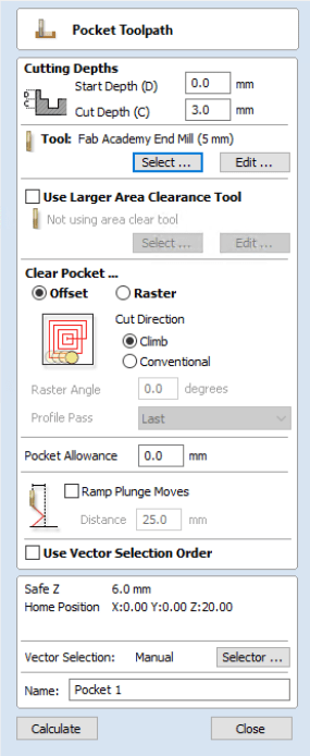
You can select exactly to which depth the cut should go. Under Clear Pocket you can set the type of path the mill should use to clear the pocket, using either Offset or Raster.
An important variable to set if this pocket is used as a joint is the Pocket Allowance. This is somewhat similar to the kerf used for laser cutting. Even though the milling machine doesn’t/shouldn’t eat more away than exactly the outlines of the shape, in practice you need to mill just a little farther outward or inward to create a snugly fitting joint.
Through experimentation, Henk had figured out that we should use a Pocket Allowance of -0.3mm.
Finally, again give your toolpath a descriptive name and press Calculate to see the 3D preview of the toolpath.
Profile Toolpaths
Profile toolpaths are those where the milling should carve out all the way to the bottom. For this we have to split the lines up into those where the machine should follow the outside of the line, and those where it should follow the inside of the line.
I first selected all the insides of my sketch; 47 for each slice and the two holes in the spine, and selected the Create Profile Toolpath.
In the toolpath options, the Cut Depth should already be set to the thickness of the material, but you can always adjust this. For the Machine Vectors, it’s important to use Inside / Left, and to set that Pocket Allowance to -0.3mm for our machine.
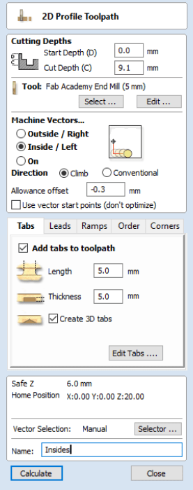
Tabs
The final important part to add are tabs. Tabs are tiny bridges between the shape that is being milled out and the remaining wood. This makes sure that the wood doesn’t move, or even worse, is ejected, during the milling process. So you want to check Add tabs to toolpath. Through experimentation Henk had advised to set the Length and Thickness to 5.0mm. Check Create 3D tabs, which are more than strong enough and easier to remove. Don’t forget to then press Edit Tabs, otherwise they won’t actually get added.
This will switch the toolpath window to one where you can set-up the tabs more specifically. Here you can say to add either a constant number of tabs per closed shape, or to add a tab for each distance of X mm, with a minimum and maximum number of tabs per shape. I’d set mine to four per shape. Press Add Tabs and the tabs will appear as yellow squares with the letter “T” in them in the design.
The text at the bottom of the tab window explains how you can interactively move, add and delete tabs. You generally want to avoid having tabs in corners, because there’re hard to remove there.
I zoomed in and checked each tab, moved some that I felt were too close to the slot corners, and also deleted a tab from the smallest shapes.
I also only kept one tab for the two holes along the spine, but in hindsight, I should’ve removed all of them because the diameter of the circle was 10mm, so there was literally nothing left in the inside for the tab to hold onto. Eventually I was left with a milled out hole and one tab (that was pretty hard to sand away in a nice way) (*≧▽≦)
When you’re done adjusting the tabs, press Close to go back to the toolpath options. Give it a good name, Insides for example, and press Calculate to see the 3D preview.
Outside Profile Toolpaths
Finally, select all the shapes where the mill should go around the outside, go to the Toolpath tab again, and select Create Profile Toolpath. Do everything the same as for the inside profile toolpaths except for the Machine Vectors, which needs to be set to Outside / Right this time.
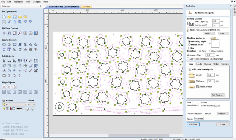
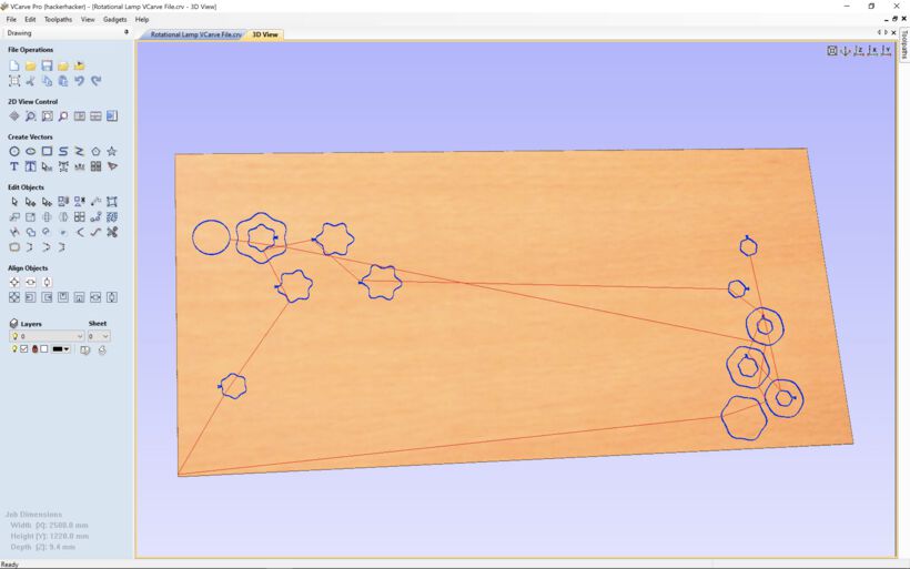
After pressing Calculate I had created all the toolpaths that I need for my design. I checked the 3D animation to see if anything weird seemed to happen, but it all looked good.
Note | You can make changes to toolpath options, but be sure to press Calculate again after making a change, to actually update the toolpath.
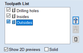
In case you want to change the order in which the toolpaths are handled by the machine, you can move each toolpath layer up or down within the Toolpath list using the arrow keys to the right.
Saving the Toolpaths
With the three toolpaths created, I could save them to two files. This is very important, you want to save the “Drilling Holes” toolpath to its own file, and have the other toolpaths, which are your actual design, be in another file. That way, you can run the job for the drilling holes first, then fasten the board to the bed with screws, and then run the actual job.
Press the Save Toolpaths button along the right side of the screen and make sure that you’ve checked the “Drilling holes” toolpath from the list and deactivated the other toolpaths. In the Post Processor select a type of processor to convert the toolpaths to the final files.
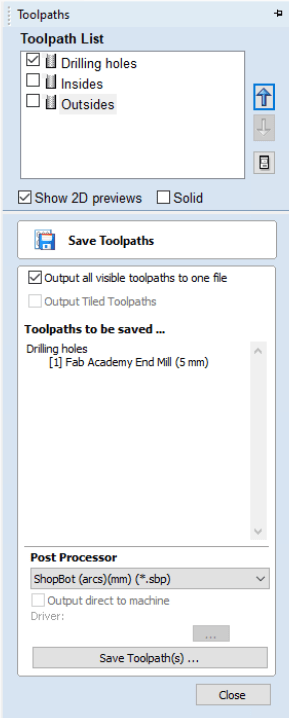
I was using an old version of VCarve (version 6) in which there were a lot of possible options to create an .sbp file, specific for the ShopBot. In the newer versions there’s only 1 option, ShopBot TC(MM)(*.sbp), split into either millimeters or inches. After a bit of searching, I found that the ShopBot (arcs)(mm)(*.sbp) was the best general option and basically the same as the one remaining option in the newer VCarve version.
Next, deselect the “Drilling Holes” toolpath and select all remaining toolpaths, and save these in a second .sbp file.
And with that I had created the final files that could be loaded into the ShopBot software to mill.
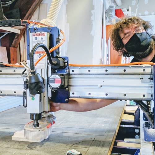
CNC Milling
At the Waag there is an (old) ShopBot CNC Mill
Safety Instructions
Henk told us on several occasions that this is the only machine that he fears. It’s the only machine in the lab that could kill you (and Neil shared a story during the lecture about a student dying and a friend losing a finger). Therefore, we started with the safety instructions.
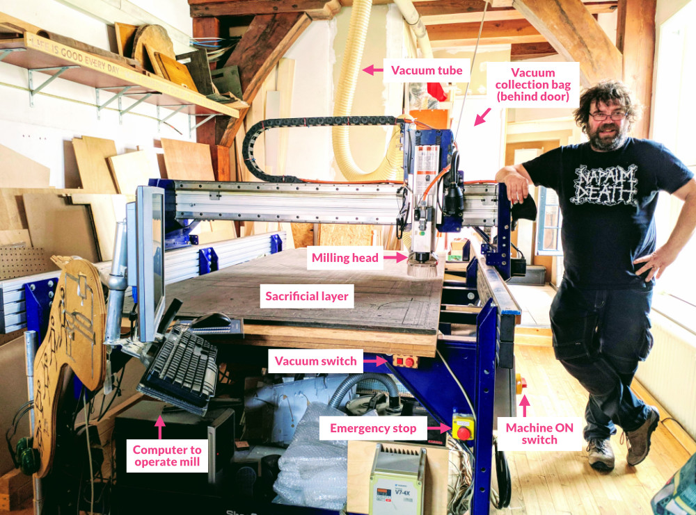
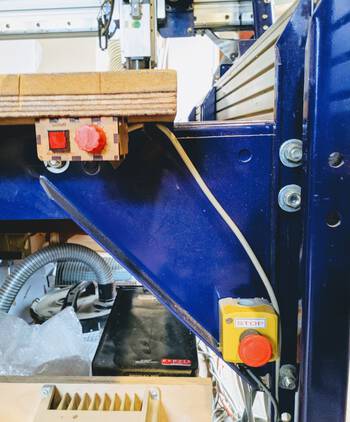
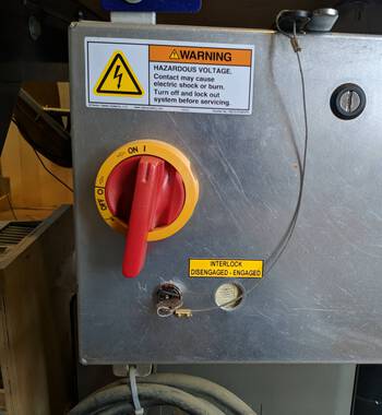
First things first, the most important button is the emergency stop button at the front of the machine (big red & yellow). With the button to stop the vacuum above it (a little to the left).
Apart from the general entrance to the room, there is also an emergency exit. And there are (at least 2) fire extinguishers in the room: One next to the emergency exit, and one next to the vacuum dust collection room.

Personal Safety
This machine is a lot stronger than we humans are, and if you’re in the way, it will not care. Therefore:
- Make sure your hair is well tied up. No loose strands at all!
- Don’t wear loose clothing that could easily get hooked on something
- This also counts for jewelry. No long earrings or necklaces, or big bangles. Best is to not wear any at all.
- Wear safety glasses.
- Ear protection is possible, however you also want to hear the machine to listen if everything is going alright. So generally, we don’t wear ear protection.
- Do not have any part of your body touching any part of the machine while it’s on / moving. Seriously, you can loose fingers if you rest your hand on the rail and the top bridge with the milling head moves over it.
Fire Safety
Apart from doing harm to our bodies, the machine also has the potential to create a fire. There is a vacuum that sucks away the chips that the mill creates. These small chips are collected in a giant bag that is placed in a small room behind the machine.
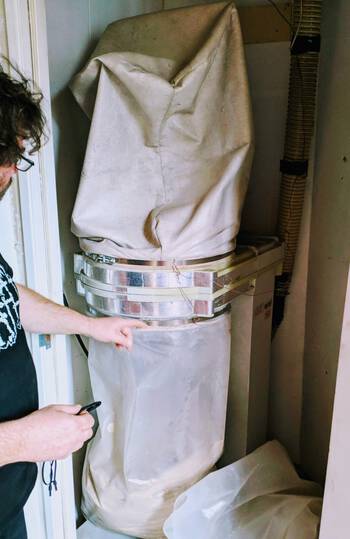
Since this bag contains tiny wooden chips, and a lot of oxygen flows through it while the vacuum is on, it only needs a small spark to start a fire.
We use metal screws to fix the wood to the sacrificial layer. The biggest risk of creating a fire is when the milling bit comes into contact with metal. This creates sparks that are then sucked into the vacuum bag.
We (try and) remove that risk by adding drilling holes to our designs, which the machine will mark on a first toolpath pass. Nevertheless, when you see or hear the bit hitting a screw:
- Stop the machine with the emergency stop button at the front of the machine.
- Stop the vacuum with the button at the front of the machine.
- Go to the room with the dust collector bag, loosen the round metal clip with which the plastic bag is attached to the machine.
- Inspect the bag.
- If a little smoke is coming out:
- Close the bag to reduce the flow of oxygen.
- Walk out of the building and inspect again.
- If a lot of smoke is coming out / a fire has started:
- Close the bag to reduce the flow of oxygen and see if that stops it enough to then walk out of the building (possibly through the emergency exit at the back of the milling room).
- If it’s really bad, throw it out of the window (do call down to warn people).
- Take the fire extinguisher and run outside to put out the fire (we never discussed this, so I’m just guessing with this last part).
Thankfully it’s never been so bad that it started an actual fire in the past, only a few people walking outside with the bag.
Other Safety
A few final notes on safety while working with the machine:
- A maximum of two people are allowed in the room with the ShopBot while it’s on (reducing possible distractions, and it’s not a big room to begin with).
- Only turn on the machine and especially the spindle when it’s necessary.
- When you turn on the machine, the bed needs to be clean. No items such as notebooks, pen, laptops, etc. can be placed on the bed.
- Make sure nothing is every touching or leaning against the machine. That includes both humans, wood, or equipment.
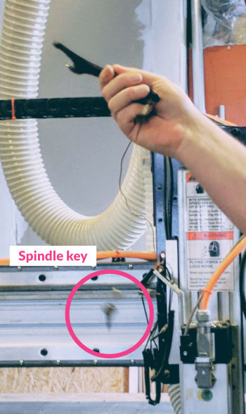
As an extra safety measure the key to turn on the spindle is attached to the wrench that you need to unscrew the milling bit. This way the spindle cannot be on while you’re changing milling bits.
The most important advice to ensure safety is to take things slow, don’t rush, and follow a strict order. Don’t try to do things in parallel.
Operating the CNC Mill
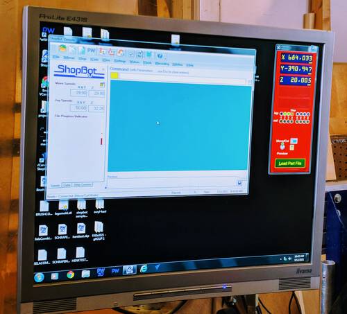
The ShopBot is controlled via an ancient computer running ShopBot V3 software. If you start the machine without the ShopBot being on (not the spindle, just the machine), you’ll get a bright yellow pop-up warning window that complains about there being no connection with the machine. So be sure to turn on the machine and then the software will open:
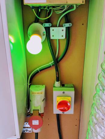
In general, there are a few switches that need to be turned on to start the machine:
- To the right of the dust collector room is a switch for the vacuum. A bright green light will turn on. This doesn’t actually turn on the vacuum, only puts it in standby.
- The small red button at the front of the ShopBot will truly turn on the vacuum.
- A big yellow-red switch to the side of the ShopBot turns on the machine. This will not start the spindle, but you can now move the machine.
- Finally, inserting and turning a small key into the hole right below the switch will turn on the spindle
After those steps the ShopBot can be started to mill. But while we’re setting things up, only put the vacuum on standby and flip the switch on the ShopBot.
One of the most important keys in the ShopBot software is the K, which will open up the keypad with which you can move the milling head manually. The long side of the bed is the x-direction, while the short side is the y-direction
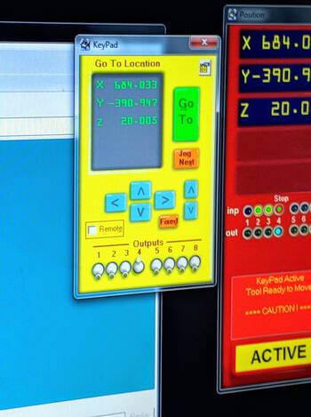
It’s easiest to use the arrow keys on the keyboard to move:
- Use the left and right arrow key to move the x position
- Use the up and down arrow key to move the y position
- Use the page up and page down key to move the z position
These keys are the reason why the computer is situated next to the ShopBot while 90° rotated. This aligns the arrow keys with the direction the milling head will move.
Initial Preparation
The sacrificial layer is used both to make sure that the mill doesn’t eat away at the actual bed below, but also as an anchor. At the Waag we screw the wood tight into the sacrificial layer. However, when these screws are removed, they leave a bump in the sacrificial layer, like a tiny volcano. Since we’re talking about precision machining, this will affect the result (which I later saw, when Henk did a quick example, but forgot to sand first, which resulted in the wood not having been fully milled through).
Therefore, first sand the sacrificial layer. Use rather rough sanding paper, such as 180. Move your hands over it to check for any bumps on the surface. But don’t go crazy and sand a dent in the sacrificial layer, you only want to remove the tiny bump.
Afterwards, vacuum the sanding dust and any remaining wood chips/dust from the bed. Also vacuum the back of the material that you’ll be using. Some dust or debris could be present on it. Afterwards, place the material onto the bed.
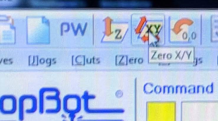
Next, make the milling head return to the absolute zero home of the bed (in the x and y position). End stops have been installed on the machine to align this automatically. Just make sure that the milling bit is up high enough to not touch the sacrificial layer.
To home the machine press the Zero X/Y button along the top row (the icon of a slanted rectangle with XY on it).
Changing Milling Bits
While the milling head is in front, it’s a good time to change the milling bit if needed. You can move the head so the machine along the y-axis so it’s more in the middle and easier to reach.
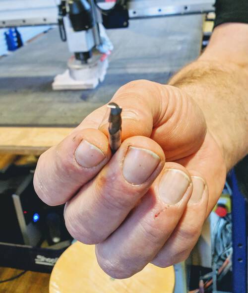
There are many different types of milling bits, both in terms of diameter, and the type (such as end mills with a flat head and ball heads). During this week we’ll be using a 5mm 2-flute end mill, since we’re only doing 2D milling. You can also have a different number of flutes which are the number of spirals along the mill. The more spirals, the smaller the chip size that is milled away. You can be more precises and clean with a larger number of flutes, but you can be fast with a lower number of flutes. For large projects, you could for example do the rough work with a 1-flute end mill, and afterwards put on a 4-flute ballhead mill to do the finishing.
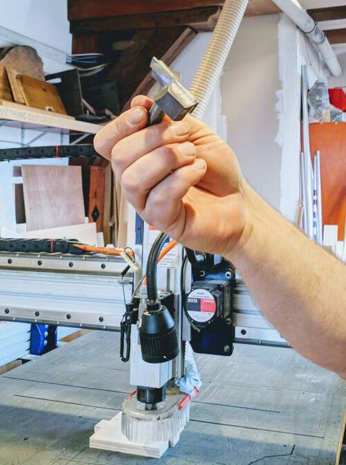
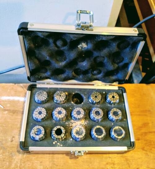
Depending on the diameter of the milling bit you’re using, you need a different collet, which hold the milling bit inside the nut of the milling head.
Put the milling bit inside the collet and the collet inside the nut of the milling head. The collet should click nicely inside the nut. If it doesn’t you have the collet in the wrong way around. The milling bit should be pushed into the collet for about 2 cm.
Make sure to measure how far the milling bit sticks out of the nut+collet. It needs to stick out at least as far as the deepest point that you want to mill, and preferable 2-3mm more. It’s a “stupid machine” and will try to go down to into the wood farther, possibly making the nut crash into the material.
To attach the nut back in, first screw it a little inward so it’s tight. However, the dust suction skirt will be in the way. You can unfasten this skirt with a wing nut at the back of the milling head. Afterwards you can push the skirt down so you’ll have easy access.
But the black wrench with the “teeth” on the lower section (that has holes where you can click the teeth into), and the grey wrench above it, and pull them together to tighten the nut into the milling head.
Afterwards make sure to move the dust skirt back up and tighten the wing nut at the back.
Setting the Origin
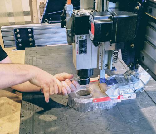
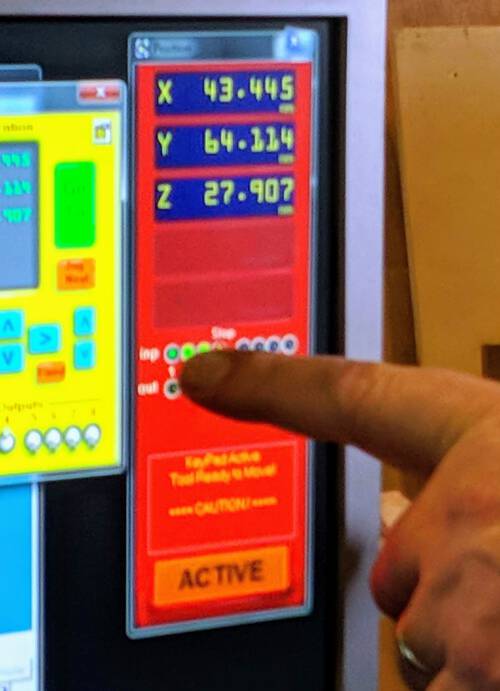
Back in the ShopBot software, we need to set the origin of the milling head to the stock/material in the x and y direction. Manually move the milling head (with the keypad / arrow keys) to the right-bottom corner of the wood. The z-axis will come later, but make sure it’s at least high enough to not touch the wood. Once you’re close to the point that you want to be set as 0,0 you can move the head down a bit to asses its location better. You want the full milling bit diameter to fit into the inner corner of the lower-right side of the wood (so don’t align the center of the bit on the absolute corner of the wood, but a little inward).
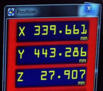
When it’s in the right spot, be sure take a photo of the current x and y positions that you see in the red window. In case something goes wrong during the milling and you need to stop the process, these numbers are the only way to align the job and try again.
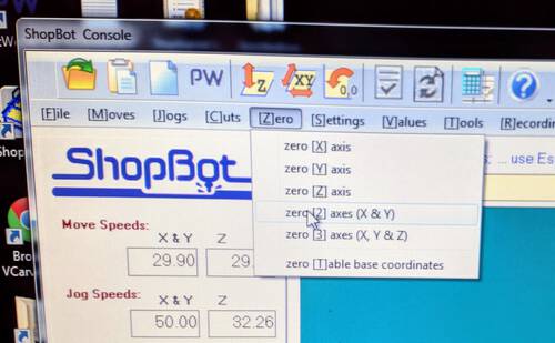
Within the ShopBot software, click on [Z]ero -> zero [2] axes (X & Y).
Z-aligning
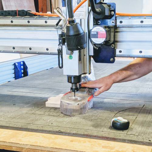
Next, we need to align the z-axis of the milling machine to the wood. We don’t want this to happen on that corner because the wood might be sticking upwards a little there. Therefore, move the milling head more towards the center of the wood.
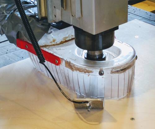
A metal plate is used so the process can be automated. The metal plate is attached to the side of the milling head. Take it out and place it in between the wood and the milling bit.
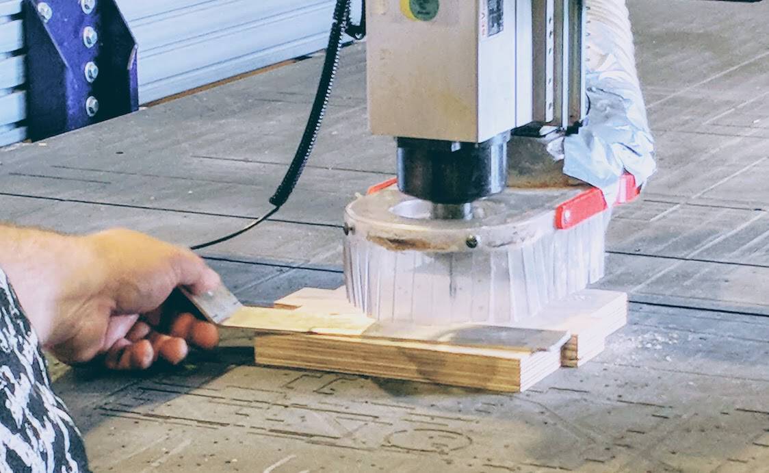
First test that the plate and milling bit can make contact by touching the plate to the milling bit and checking that the first radio button within the red window of the ShopBot software lights up green.
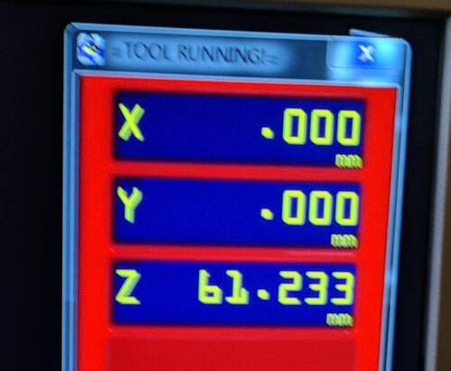
If that looks good, place the metal plate onto the wood carefully checking that the milling bit will touch the metal when it goes down. Otherwise the machine will keep pushing the head down through your material during the z-aligning process. Next, press the Zero Z button along the top (the slanted rectangle with the Z).

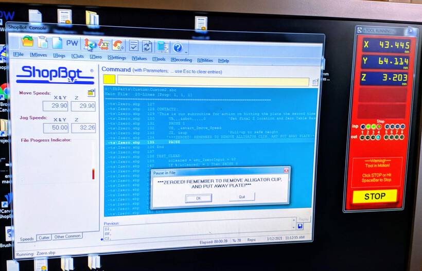
The machine will slowly move down until it makes contact with the metal plate. When its done, the z value in the red window will read 3.20Xmm which is exactly the thickness of the metal plate.
Afterwards open the keypad (K) and move the milling head upward a little before removing the metal plate, otherwise you’ll be demolishing the blades of the milling bit.
FYI | In case you change milling bits during a run, you’ll have to z-align it again of course.
Now the machine is ready to start its milling job.
Starting a Run
Load the .sbp gcode file with the toolpaths (from VCarve Pro) into the ShopBot software by going to File -> Part File Load. This will open up a new window with a very odd “school notebook” design. Nothing (should) be changed here.
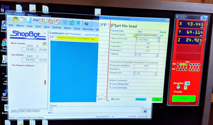
Now is the time to turn on the spindle and vacuum. Use the button at the front of the machine to turn on the vacuum, and then insert the key into the side of the machine and turn it to start the spindle.
Check one more time that nothing is leaning against the machine, including you. That you’re wearing your safety goggles, have no loose hair or clothes flapping about. That you’re feeling zen, and take a moment to go over the steps in your head to make sure you haven’t forgotten anything.
Now, you’re ready to press the green START button (while feeling the stress of finally turning on the machine!! (⑉⊙ȏ⊙) )
Note | Using the spacebar you can pause the machine. However the spindle will keep turning. Therefore, only pause the machine while it’s in between paths and in the air.
Doing a Test Run
It can be handy to do a test run first in the air to see if things seem to be going well. For this, place a material on top of the wood that is thicker than the maximum distance that you’re planning to mill. Redo the z-aligning on top of this piece of wood.
For a test run do not start the spindle and there’s no need to turn on the vacuum.
If all seems to be going well, you can stop the test run by pressing the big STOP button in the red window, or by pressing the spacebar (this will pause the run, but you can then also choose to stop it). Afterwards, don’t forget to redo the z-aligning on the actual wood surface.
Fixing the Wood to the Bed
One thing that we’ve not talked about yet is how to fix the wood / material to the bed. At the Waag we screw the wood into the sacrificial layer. The reason why I haven’t discussed it yet, is because we create drilling holes into our design, and the first toolpath that the machine will do is to mark the wood at those places, so we know exactly where to place the screws to make sure that the drilling head won’t bump into them while doing the actual milling.
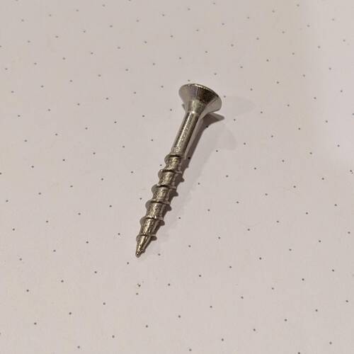
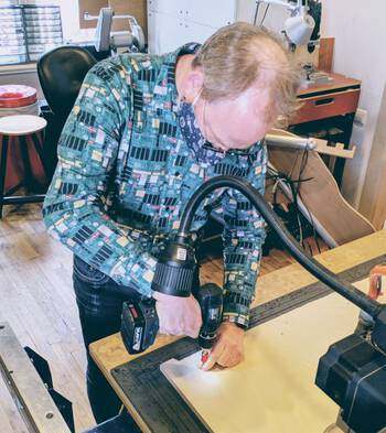
With the drilling holes toolpath loaded into the ShopBot software, and it having done its run to mark them, turn off the spindle and the vacuum. Use the keypad to move the milling head out of the way so you can screw the board to the sacrificial layer. For this woodies are used (screws for wood) together with a power drill.
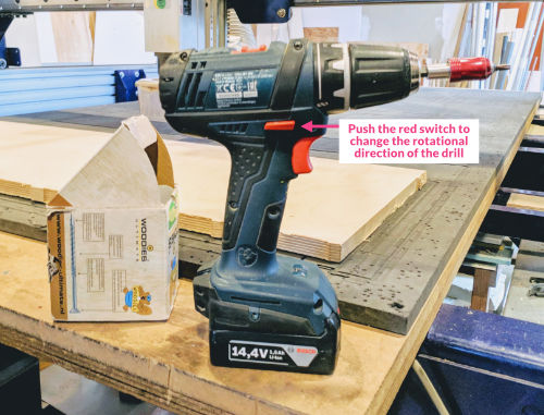
The drill has a “switch” in the center that you can push left or right (the middle red button thingy on the photo above left). This will make the drill rotate clock- or counterclockwise, one direction for screwing in and the other for taking the screws out.
When you place the screw into the holes that the machine has made, be sure to push down with one hand on the wood, somewhat next to the hole, and push down on the drill as well as you screw it in. Otherwise, the wooden board will be lifted up as the screw enters the sacrificial layer.
After fixing the wood to the bed redo the z-aligning! The wood will have been pulled down.
With the wood fixed to the bed, and the z-aligning done again, you can load the actual toolpaths file and do the full run. If at any point you see the machine moving to a screw, be sure to pause it (if it’s in the air) or do the emergency stop if it’s in the wood.
After the Job is Done
After the job is done, turn off the vacuum and turn off the spindle. In case you’re done for the day, close the software and afterwards shut down the ShopBot with the switch and the vacuum with the switch in the back.
Take the screws out of the bed. If you break any screw be sure to get them out of the sacrificial layer once the job is done! Otherwise, the milling machine might hit it in some (far) future job, potentially causing a fire.
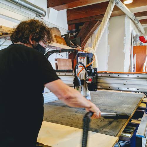
With all the screws taken out, slowly lift the board and remove it from the bed. Use the vacuum machine to clean up the bed from wood chips and dust.
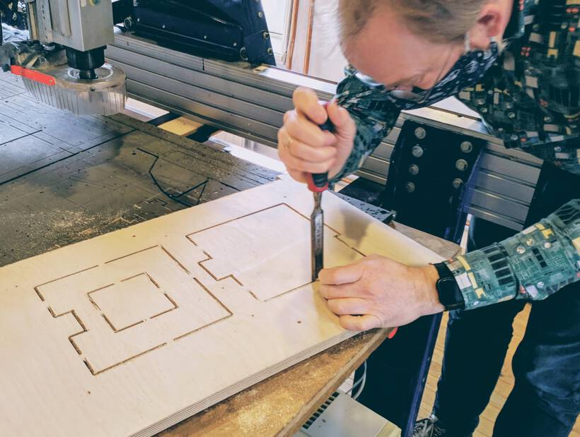
Since tabs were used to make sure that all pieces are still a little bit connected to the wood, you’ll need to use a box cutter or a chisel to cut off the tabs and remove each piece from the wood. You might even just push the pieces out of the board, but this can more easily result in chunks of the wood coming with it, leaving ugly marks on your milled out shapes. There will no doubt be lots of rough ends on the wood, so it might be good to wear some protecting gloves.
Now comes the post-processing where you’ll be spending quite some time to sand the edges and corners of each piece [¬º-°]¬
Summary of Steps
To summarize the steps explained above, assuming that the right milling bit is in already, and you know it’s sticking out farther than the thickness of the wood.
- Sand the surface of the sacrificial layer
- Vacuum the full bed and also the bottom of the wood material
- Place the wood onto the bed and vacuum the top
- Make sure no wood or other items are leaning against the machine
- Turn on the computer attached to the ShopBot
- Turn on the vacuum dust collector in standby mode with the big switch right of the door to the dust collector
- Turn on the ShopBot with the switch to the right of the machine (don’t insert the key!)
- Open the ShopBot software
- Home the milling head to its absolute zero with the Zero X/Y button
- Manually move the milling head to where you want the origin of the job to be with the keypad (press
K) and the arrow buttons on the keyboard- This is generally the lower-right corner of the board
- Write down the x and y coordinates
- Click on [Z]ero -> zero [2] axes (X & Y)
- Z-align the milling head to the wood using the metal plate somewhere towards the middle of the wooden plate
- Make sure that the plate and milling head make contact by first pushing the plate against the bit and seeing that the green indicator in the software lights up
- Click on the Zero Z button to do the alignment
- Load the
.spbfile in the ShopBot software with File -> Part File Load - Check again that nothing is leaning against the ShopBot, that you have no loose hair, clothes or jewelry and are wearing safety goggles
- Perhaps do a test run first? If yes, see the “Doing a Test Run” section above
- Turn on the vacuum with the button at the front of the machine
- Insert the key on the panel to the right of the machine and turn it to start the spindle
- Start the job for the drilling holes by pressing START
- In case it’s needed, pause the job by pressing the
spacebar, but only while the head is in the air - In case it’s needed, press the emergency button (e.g. when the drilling bit hits a screw)
- In case it’s needed, pause the job by pressing the
- After tje job is done, turn off the vacuum and spindle
- Move the milling head out of the way
- Screw the wood into place (apply force!)
- Redo the z-aligning
- Load the actual toolpaths file into the ShopBot software
- Check yet again that nothing is leaning against the ShopBot
- Turn on the vacuum, turn on the spindle and press START
After the full job is done:
- Turn off the vacuum
- Turn off the spindle
- Unscrew all screws (leaving none behind)
- Remove the wood
- Vacuum the bed
- Remove each piece from its tabs with a chisel or box cutter, or pushing it out
- Sand, sand, sand away
Testing the CNC Mill
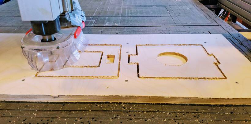
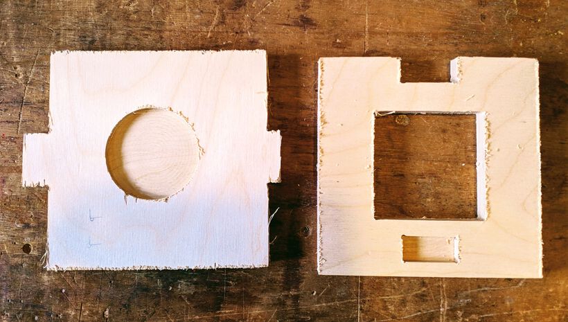
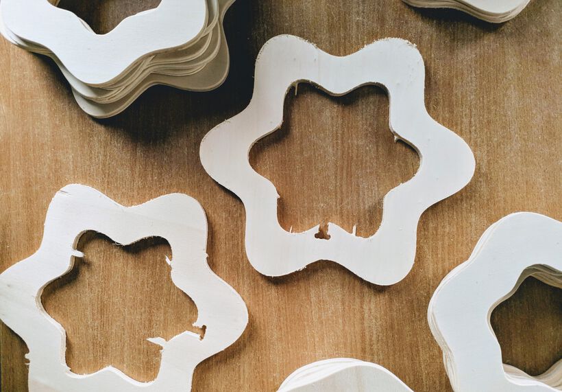
To go through the steps ourselves and get to know the machine, we milled two squares that have some pockets and fingers to test out the fit, and things such as dogbones and tabs. Henk did not want all four of us students working on each step at the same time, because it could more easily lead to chaos and missed steps. Therefore we divided up the work.
Nicole and I set up the toolpaths using the design. The dimensions of the wood (17.9mm) to use were already set-up from the explanation we got about VCarve just before. We placed dogbones along the corners, created pockets and profile toolpaths, added a -1mm offset, and checked the final preview rendering to see if all seemed ok. We made sure to create a separate toolpath file just for the drilling holes, and another one for the actual toolpaths.
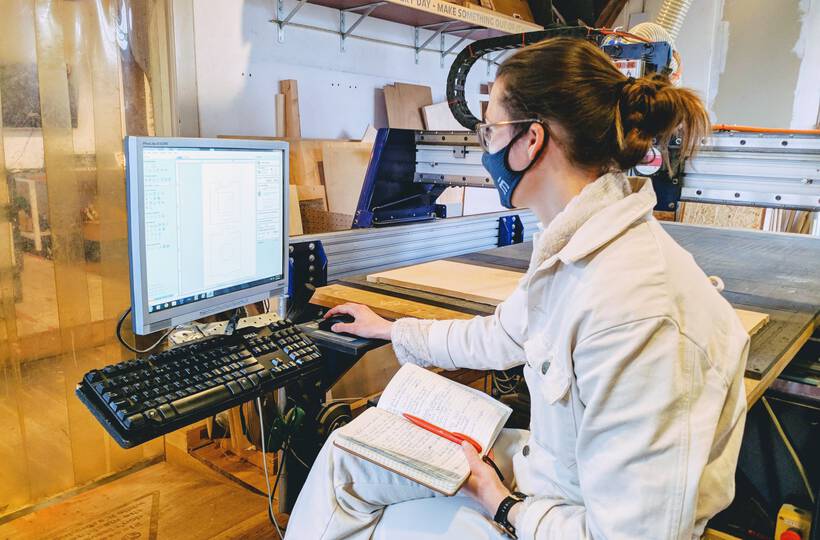
Afterwards, Phil and Erwin took over to prepare the machine. Sanding and vacuuming the bed, placing and setting the origin, z-aligning it and running the first job to mill out the screw holes. Here I only looked from a distance as they went through the steps. I did ask to screw in a few screws, because I’ve only handled a power drill about 5 times in my life, so I could use some experience (*≧▽≦)
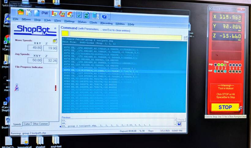
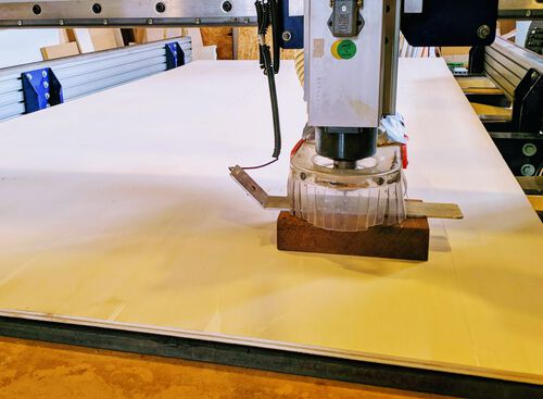
Phil and Erwin redid the z-alignment again, and started the machine on the second file that contained the true toolpaths. It was interesting to see how the ShopBot software shows each line of the gcode that it is currently processing (image below right).
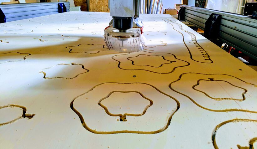
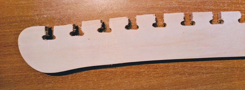
Having an 18mm thick board, and only going 2.5mm in depth per pass, it took 8 passes before one piece had been fully milled! It was interesting to see how the machine made a little “jump” when it was working on a (near) final layer due to the tabs:
Since these were small pieces, the run was finished in a few minutes. I tried to measure how fast the head was moving on the straight sections of the outside squares, and felt it was about 50mm/s.
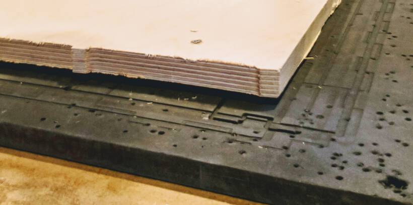
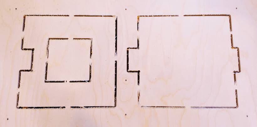
Afterwards, we unscrewed the wood to check the results. From the bottom we could see the tabs and that the drill had cut through the whole wood fully on almost all places (perhaps it was just through the wood along the lower-right of the image below right).
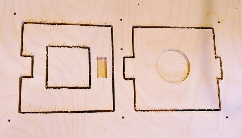
I was kind of surprised that the result was looking that rough. I thought that the images I’d seen on blog from previous students looked a lot cleaner along the edges. That wasn’t a very good prospect for my design, which had so many curved outsides that are not easy to sand… ⊙﹏⊙
Creating My Lamp
My four hours slot to use the ShopBot was on Monday afternoon. I had already prepared my VCarve toolpath files, so that saved me some time thankfully.
Milling the Board
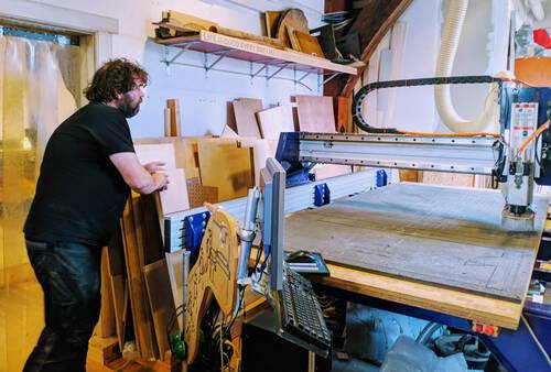
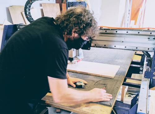
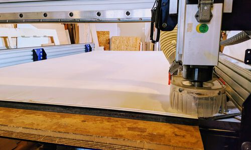
I followed the steps as I outlined in the Summary of steps section. I sanded the sacrificial layer of any volcano bumps that I felt. Vacuumed the bed, then vacuumed one side of the giant 250x122cm wooden sheet and placed it on the bed. Turned the dust collector/vacuum to standby and flipped the switch on the ShopBot to turn it on.
Within the ShopBot software I started by homing the machine to its absolute zero point, and then set the origin of my run (to x=11.776 and y=17.012).
Because I’d prepared my VCarve files on a different version than the one used by the lab, Henk wanted to first do a test run of the drill holes to see the boundaries that the machine would use. I therefore z-aligned the machine on the extra thick block of wood on top of my wooden sheet.
Thankfully, the test run went well. I therefore z-aligned again on the actual wooden sheet (somewhere along the middle right-ish side of the sheet), loaded the drill holes toolpath into ShopBot, put the key into the machine and turned it to start the spindle and turned on the vacuum, and started the job.
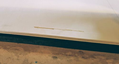
The wood at the front was quite bended, and while moving from drill hole to drill hole, the milling bit even touched the wood for a bit and ate out a line. Thankfully it didn’t happen in any other location, and the place where some wood was eaten away was a place that wouldn’t be used further anyway.
Having turned off the spindle and vacuum, I grabbed the power drill and the “woodies” screws and climbed onto the ShopBot bed to screw them into the holes that had just been created. I did have to change batteries because after a few screws the power drill wasn’t able to screw the woodies in completely anymore.
Having finished with that, I z-aligned again, loaded the lamp shape toolpath file into the ShopBot, turned on the spindle and vacuum again, and at that point there was nothing left to do but to get over my nerves and actually start the job.
Henk came to watch and thankfully my first shapes were quite small, so we could quickly see if the mill had gone through the wood completely, which it didn’t… I paused and then stopped the machine (while the milling head was in the air of course).
- We then z-aligned again, maybe I’d picked a spot that was just a tiny bit higher. But that didn’t make any difference.
- Henk thought perhaps the milling bit wasn’t sticking out enough and couldn’t actually go down lower, so he opened the milling head to lower the bit. But that didn’t make a difference either.
- I then set the depth of my wood to
9.2mmin VCarve and saved the new toolpaths. That made some difference, but not enough sadly. - I z-aligned again, but no difference.
- I then set the depth in VCarve of my sheet to
9.3mm. I then finally went through almost fully on the first shape and fully on (practically all) the shapes it milled out afterwards.
So we decided that if it went through most of them it was time to continue. Those that didn’t go through fully could probably be pushed out.
The rest of the milling process went by without any issues. It actually went much faster than I thought, it was done in 1h45m, which wasn’t too far from the time that I had roughly calculated.
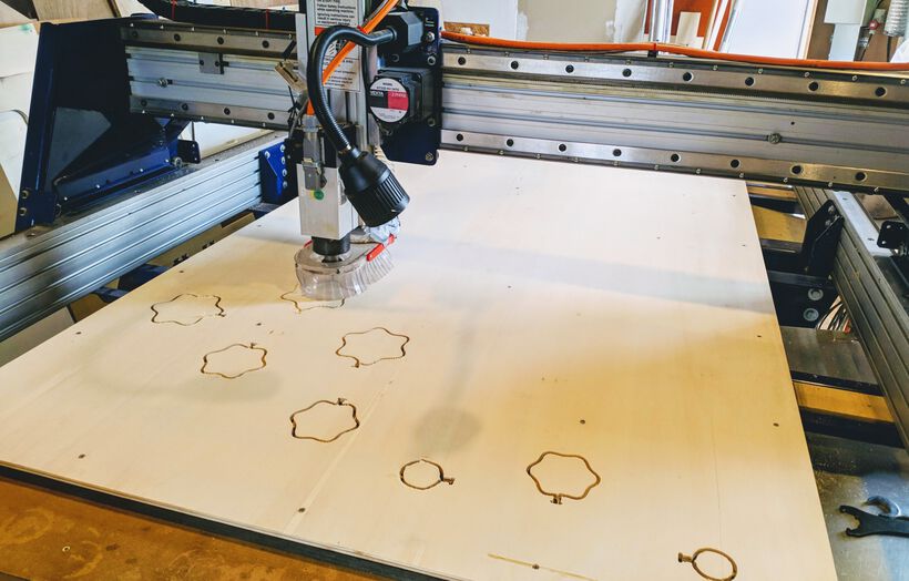
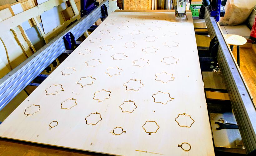
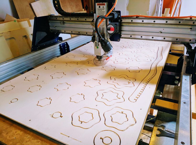
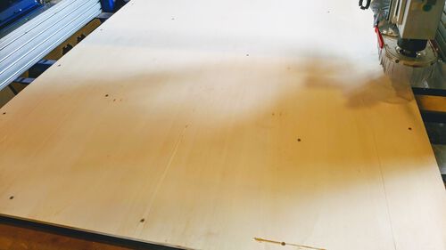
However, at the far right corner of the board, it hadn’t gone through enough, there was definitely too much wood left still. I checked the full plate and saw that there were about three blobby shaped areas where the milling bit hadn’t gone through either.
Since it was only 16:00 and I had till 17:00, I created two new toolpaths in VCarve with only the few inside and outside shapes where it hadn’t gone through fully and set the thickness to 9.4mm.
I redid this run and it did make a little difference, but not a whole lot. But at least it seemed that enough was milled away to be able to push out the shapes.
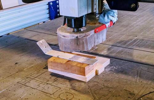
After I fully turned off the ShopBot I climbed onto the bed again to take out all of the screws. I then slowly started pulling out the wooden sheet and taking out each lamp piece along the way. My shapes were quite small so none of them fell out, they actually needed a little force to be pushed out. I noticed that I definitely didn’t need four tabs for each of these pieces. They came off leaving ugly marks, or taking part of the wood with them sadly.
And my gosh, did they need a LOT of sanding, they were so rough!! Especially the slots and t-bones were rough, and naturally they were by far the hardest to sand (ᗒᗣᗕ)
Still at the lab I started to sand each piece by hand. I timed myself and was able to properly sand one piece each 10 minutes. Wait, I have 47 slices and one complicated spine to sand, so that would take me about 10 * 47 + 60 = 530 minutes to finish……
That’s almost 9 hours of sanding!!! ✖_✖
And I had only 1 more day to finish it. I also had quite a lot of documentation left to, having spend so long on creating the design in Fusion 360 + python. O, and I had a medical appointment on that day as well, taking out 3 hours of my time. Furthermore, my arm would not survive 9 hours of sanding even if I did somehow have 9 hours available on the next day.
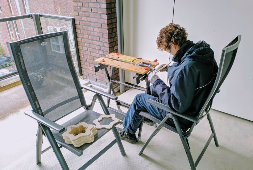
I therefore spend 2 hours that evening comparing multitools and ended up purchasing a Dremel 4000 that I could pick up the next morning ┐( ̄ヮ ̄)┌
However, it was not easy to use the Dremel on my curved shapes. While holding the Dremel in one hand and the shape in another, the head of the Dremel was often whisked away because it rotates so fast, and then dug into the side of the wood. So at the start I only used the Dremel to remove the big tabs from the sides and did the rest by hand. Of course, that didn’t make the process go a lot faster than before.
Thankfully, my partner thinks much more practically than me, and when he came home he figured that we had to fix the Dremel in place and then use two hands to move the shapes past it. This definitely made it possible to use the Dremel, but the result was not quite as nice as doing it by hand. But by now it was time to just focus on getting it done decently enough, not perfect.
He saw how desperate I was getting with this lamp, and so he sacrificed his evening as well to sit outside, in the watery cold, to roughly sand the edges of each piece, while I was doing the spine and all of the tiny slots and t-bones by hand.
We worked till 1am on that evening, my arm was definitely over-exerted and hurt like hell, and still there were 11 slices left [¬º-°]¬ My partner stayed for an hour longer the next morning to sand those as well, while I started setting up the lamp between two chairs.
With 47 slices that looked like each other quite a lot (from piece to next piece), it was still a bit of a challenge to assemble the slices in the correct order. First I tried to stack the slices from small to big, but sometimes the difference was just too small to know for sure. I therefore had the design in Fusion 360 open, looking straight at the slices. I would then take the slice I thought should be it, and compared it to the design on my mac to see if it matched, but also to know the exact orientation of the slice. If it was a match, I would hide that slice’s component in Fusion 360 so the next one would be visible, and hung the slice onto the spine.
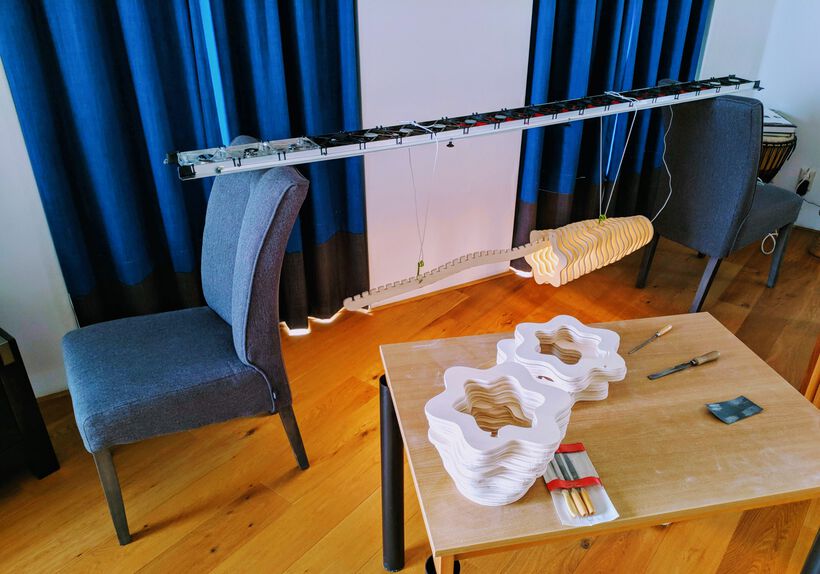
It was slow going, but I got there in the end, without mixing up any slice even! ᕦ(ò_óˇ)ᕤ
Final Result
And so, 30 minutes before the “end of the week” review started, I finally had a working lamp! I had gotten an LED strip to use for the photos from Henk (thank you!) that I had sticked to the bottom of the spine.
A close up shows the rough sides from broken tabs, so in case we actually want to hang this lamp above our dining table, I will need to sand the ±35 remaining slices by hand as well (*^▽^*)ゞ
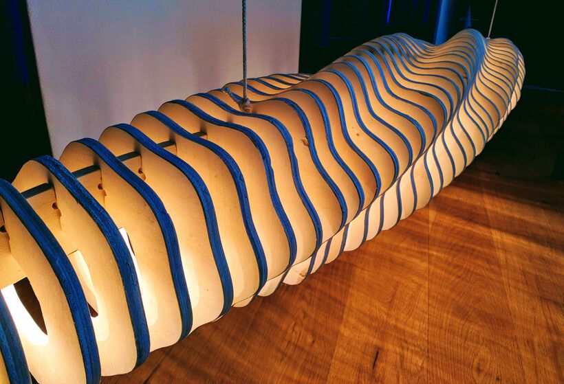
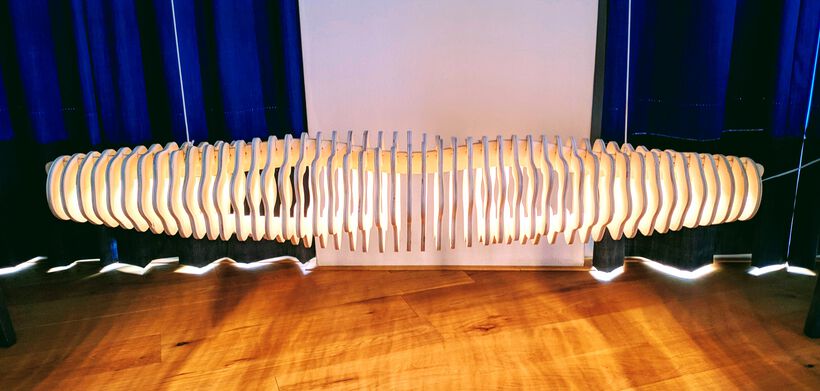
I like the interesting shadow patterns that it’s creating on the ground as an effect that I hadn’t expected.
Reflections
Damn! This week! Took SO MUCH TIME! I thought previous weeks were hard, but this one really blew them out of the water.
What went wrong
I’m sad that many of my slices are missing chunks along the sides because tabs broke off while taking each slice from the wood or broke off during the sanding ಡ_ಡ
Both Henk and I were also surprised that I had to use 9.4mm depth on some of the shapes to have them (mostly) milled through. Henk thought that perhaps the sacrificial layer needed a releveling, because some areas could have been sanded down too much after a year of use.
What went well
Well, I didn’t hit any screws! (⌐■_■)
But all kidding aside, I’m really happy that I did have an actual lamp. My design was fully milled and the slices fit the spine. Plus the spine didn’t collapse after hanging all the slices in it. So even though my perfectionist side isn’t totally satisfied, I should already be happy with having a lamp.
What I would do differently
In short, I should’ve gone for that laptop stand idea I had as my second option ┐( ̄ヮ ̄)┌
I had not overseen how long it would take my to create this design and then also the sanding for post-processing.
I should’ve definitely not used the Fusion 360 python API for this week. It was just too much work to learn both the API and some python parts and to then create a functional design with. Every little step took hours, not minutes.
About the design of the lamp, I’m happy, but I definitely see room for improvement now that the lamp is hanging in our room for me to see. For example. I might still start from a circle, but go to the full blobby hexagon much faster. I felt that the curves rotating along the lamp were not visible enough. I also wouldn’t mind to have the center radius be ±5cm larger still. Although I’m not 100% sure if that would’ve still fit the board.
Also, I should’ve used much fewer (and smaller) tabs on shapes that are this small. Two would’ve been enough to keep them in place I think.
And, if not using high quality wood, I really need to consider what I would want to make with cheap wood due to the sanding. Bigger shapes with long straight angles would be much better in those cases, and not a design with basically no straight edges. I still can’t lift a full glass of water with my arm, after all the sanding needed to even get in a “barely good enough” state.
Wrapping up
I made something big! It worked! I’ve never made something so big before (^▽^) . But I think I prefer the amazing perfectionism of the laser cuter. I would definitely like to see how the result would look when higher quality wood is used, because the wood that we used this week was just coming out too rough for the kinds of items that I would like to make.
Also, I want to thank my partner for all his help this week ♥ I truly could not have finished (in time) without his help, in giving me access to VCarve on a windows PC, to having remote access to that PC from my Mac, to helping with the sanding and creating a simple system to hang the lamp from.
All Files Together
- The final Fusion 360 python script | python file
- The final
.dxffile from Fusion 360 | dxf file