This week the programming became real! After a brief (but not easy to get working) taste during the “Electronics Design” week to test my board, I now learned a lot more about how to program my board and make it do some fun and simple tasks, often involving the LED.
Assignments
Our tasks for this week are:
- Individual assignment:
- Read a microcontroller data sheet
- Program your board to do something, with as many different programming languages and programming environments as possible
- Group assignment: compare the performance and development workflows for other architectures
Hero Shots
Showing a final result that I programmed on my board for the tl;dr and hopefully showing you why the rest of this very long blog could be interesting to read (⌐■_■)
Programming My Board
Two weeks ago, during the Electronics Design week Henk had created a schematic that included an ATtiny412 microcontroller, an LED, button, phototransistor, and a UPDI and FTDI connection (and two resistors and a capacitor), which we’d all turned into an actual board.
I had already tested my tiny hexagon board to run a simple echo program that returned whatever I typed.
It was now time to make the board do more and start tinkering with our own code. This is generally easiest to pick up while using the Arduino IDE, combined with the megaTinyCore board manager for it. I’d already installed both of these two weeks ago when testing my board.
I opened the Arduino app and started a new file. As a reminder:
- I set the Board under Tools to ATtiny412, which updates a whole array of things.
- I set the Port to my UPDI (being
D30A3T7I). - I should not forget that the Programmer should be set to Serial Port and 4.7k, otherwise you could end up seeing only
java.nullExceptionErrortype results being returned when trying to upload a program to the board.
A Blinking LED
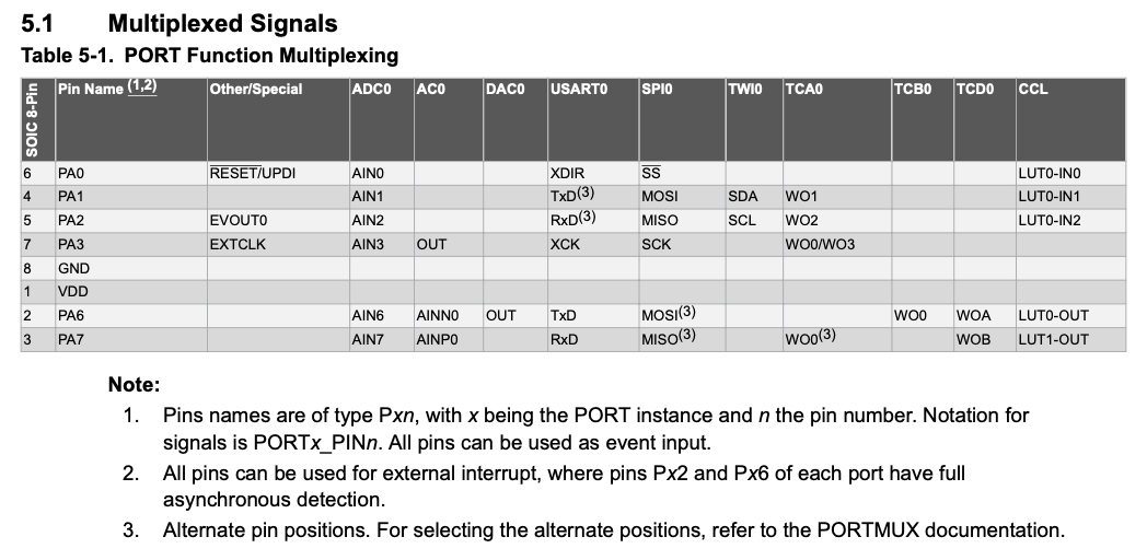
I was really eager to start with my LED, to make it blink. During instruction day at the lab, Henk showed an example of a tiny script to make the LED go on and off after specific intervals. In that example it uses pin number 7 (int led_pin = 7;). However, I already knew that on our boards things were different, because the schematic that we followed had switched the default TX and RX pins to their alternate positions. Thankfully, many pins can be programmed to take on different functions. Only the pin connected to power VCC and ground GND are fixed.
I therefore had to figure out the pin number on our board connected to the LED. Having learned from the testing that the megaTinyCore website contains a wealth of information, I started looking there, and quickly found the section about “How to refer to pins”. Although it sadly doesn’t share actual code snippets, it said “Defines are provided of form PIN_Pxn, where x is A, B, or C, and n is a number 0-7”. Looking at our schematic, I saw the the LED was connected to pin PA6, and thus I updated my code to:
// Blink the LED on and off every two seconds

#define led_pin PIN_PA6 // This uses the ATtiny pin number
//const int led_pin = 0; // This uses the Arduino pin number instead

// The setup function only runs once when you press reset or power the board
void setup() {
  // Use the alternate pin positions due to swapped TX&RX pins
  Serial.swap(1);
  // Initialize digital pin led_pin as an output
  pinMode(led_pin, OUTPUT);
}

// The loop function runs over and over again forever
void loop() {
  digitalWrite(led_pin, HIGH);   // Turn the LED on (HIGH is the voltage level)
  delay(1000);                   // Wait for a second (= 1000 microseconds)
  digitalWrite(led_pin, LOW);    // Turn the LED off by making the voltage LOW
  delay(1000);                   // Wait for a second
}
The code above is an Arduino flavor mixed around C. C is a low-level programming language that is very efficient and fast, but that’s not quite as easy for mere humans to write and understand. Therefore, many many programs have written wrappers around this that are more human friendly, such as python, but also Arduino. In Arduino these are wrapped into libraries. These libraries contain functions (e.g. digitalWrite is function) that help you perform a specific task in only 1 line. Under the hood, that function could consist of a few to hundreds of lines of C code that actually do the work in the end.
Libraries therefore make it easy for humans to get started and write code, but it does mean that those libraries need to be added to the script you’re writing when they’re being uploaded to the microcontroller, increasing its size. The fact that the library needs to do the “translation” to C for you, also means that it’s (much) slower than if the script was written in pure C.
If you’re script is small, and you don’t need ultra fast processing, then using the libraries is no problem. But in case you do run into performance issues, it might be time to look into ditching the libraries and writing your code in pure C.
Getting back to my script. I pressed the Verify button (the circle with the check mark) which gave no compiler issues. I then pressed the Upload button (the circle with the right-pointing arrow next to the Verify button) to compile and upload the program to my board. It took a few seconds, but the output I was seeing from the console was indicating that all was going well.
I looked at my board and saw a blinking LED! ( ^∇^)
Although using delay works for this dummy example, it wouldn’t be a smart approach to use in generally, because the delay blocks the system from doing anything else in the meantime. You instead want to work with timers, but I’ll hopefully get to that later.
Pin Numbers
In general, the microcontroller controls the signal (the voltage) to its pins, and there are two ways of controlling this, via analog or digital means.
In the datasheet there is a tiny image on page 14 of the ATtiny412 called the pinout with some base functions of the different pins.
I tried to gather what all these pin options meant:
- VCC | Power supply
- GND | Ground
- PA | The name for digital pins, which all of these pins are
- PB | The name for (purely?) analog pins, which the ATtiny412 doesn’t have, but the green indicates an analog functions that five of the pins have. I think this means that they can all do ADC or Analog Digital Conversion
- RESET | Through this pin you can reset the microcontroller
- UPDI | Through this pin you can program the board via a UPDI connection - this is linked with the RESET
- EXTCLK | External Clock | Where you can connect this pin to an external clock, such as a resonator
- GPIO VDD power domain | I wasn’t able to find a clear answer online about what this means, but I think it means that the microcontroller can set a voltage on each of these pins?
To see what Arduino pin numbers are associated to it, you need to find the Arduino pinout overview. I googled “ATtiny412 Arduino pinout” to see if I could also make the blinking work while using the pin number that the LED is connected to according to Arduino/megaTinyCore.
I found several Fab Academy websites that showed images of the pinout (^▽^) . One site pointed to the source of the pinout in the megaTinyCore documents:
Here I saw that the PA6 pin was probably the number 0 pin according to the megaTinyCore library. I commented out the #define led_pin PIN_PA6 line and instead added int led_pin = 0;. I uploaded it to my board and it all worked, no errors, and my LED started blinking again. Nice!
From the Arduino pinout I have a few new pin names, which I think mean the following:
- MISO | Master In Slave Out | Which is the pin to use to send data from the slave to the maser.
- MOSI | Master Out Slave In | Which is the pin to use to send data from the master to the slave / peripherals.
- SCK | Serial Clock | Which are the clock pulses that synchronize data transmission generated by the master.
- SCL | Serial Clock Line | The same as the SCK, but this one is used for an I2C I believe, while SCK is used for SPI communication.
- SDA | Serial Data | The pin that carries the data when using I2C I think?
- DAC | Digital Analog Conversion | This allows you to convert digital (numeric) values into analog signals so you can have output voltages that are variable between 0 and 5V, instead of only either 0 or 5V. From the ATtiny412 datasheet there is one DAC pin (PA6, connected to our LED), which is 8-bit.
- ADC | Analog Digital Conversion | This is doing the reverse from above, where the incoming analog signal is converted into a digital one. This has to be in steps, and the higher the number of steps, the higher the resolution. With a 10-bit ADC you can detect 1024 (being
2^10) discrete analog levels, while 8-bit can detect 256 (2^8) discrete levels. If I understand the ATtiny datasheet correctly (from the Peripheral Summary), then all 6 (non VCC/GND) pins are ADC (at 10-bit 115ksps). - TXD | Transmit | The transmitting pin to do serial communication (UART or USART I think? Which is serial over USB).
- RXD | Receive | The receiving pin to do serial communication.
And there are a few extra marks, such as the tilde (~) meaning a PWM pin (Pulse Width Modulation), which I’ll get to in the fading LED example below, and the alternate locations of the TXD, RXD and MOSI, MISO which I’d already discovered during my testing, because our board is making use of these alternate positions. I’m not quite sure what the async interrupt truly means.
A Fading LED
To create an LED that seems as if it’s fading, you can use the PWM pins. Pulse Width Modulation is a technique for getting analog results with digital means. It’s explained well on this Arduino page. It comes down to varying the amount of time during a pulse that the signal is HIGH / ON.
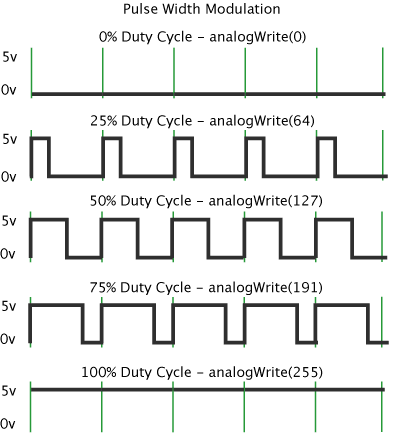
There is a handy Fading Example on the Arduino website that uses this PWM technique, using the analogWrite function (instead of the digitalWrite function from the “blink” example). The analogWrite function can take integers between a value of 0 - 255, where the higher, the brighter the LED should become.
However, I noticed that the pin that our LED is connected to, pin PA6 does not have PWM. Another sad by-effect from having switched the TX and RX pins. Using the analogWrite function, and the “fade” example therefore didn’t work. I compiled and uploaded it, but my LED remained off.
I therefore had to mimic a PWM through purely software means. This is done by using the digitalWrite function combined with the delay to basically create your own pulses. You make your own pulses of width X milliseconds long, and using the digitalWrite you turn it on for, say 20% of the time of that pulse and off for the remaining 80% of the time of a pulse.
I definitely needed a first starting example to wrap my head around it, but eventually it clicked and I understood what was happening and adjusted the examples to my own version:
// Using "software PWM" to fade my LED
// Loosely based on: https://forum.arduino.cc/index.php?topic=104572.0

const int led_pin = 0;
float steps = 25; // The max time of each step
float fade_step = 0.5;
// It takes (steps / fade_step) steps to go from OFF to ON
// the "delay()" function should take "unsigned long"
// but I really need 0.5 milliseconds or less
// and using the delayMicroSeconds() doesn't work,
// because it can't handle numbers above a few thousand microseconds
// which is only a few milliseconds

void setup() {
  Serial.swap(1); //Because I have swapped TX/RX pins
  pinMode(led_pin, OUTPUT);
}//void setup

void loop(){
  // Fade to bright | Runs from 0% -> 100%
  for(float i = 0; i <= steps; i += fade_step) {
    digitalWrite(led_pin, HIGH);
    delay(i);         // ON for this long
    digitalWrite(led_pin, LOW);
    delay(steps - i); // OFF for this long, the remaining "pulse width"
  }//for

  // Stay on for a while
  digitalWrite(led_pin, HIGH);
  delay(50);

  // Fade to dim | Runs from 100% -> 0%
  for(float i = steps; i >= 0; i -= fade_step){
    digitalWrite(led_pin, HIGH);
    delay(i);
    digitalWrite(led_pin, LOW);
    delay(steps - i);
  }//for

  // Stay off for a while
  digitalWrite(led_pin, LOW);
  delay(50);
}//void loop
Which made my LED fade nicely:
The code above isn’t totally neat code, because the delay functions wants an unsigned long as a value, whereas I’m giving it a float. However, if I increased the step size from 0.5 to 1 the visual result was a very jagged fading on and off, whereas using 0.5 shows a pretty nice smooth fading.
I also couldn’t use the delayMicroSeconds function, because according to the docs “the largest value that will produce an accurate delay is 16383. For delays longer than a few thousand microseconds, you should use delay() instead.", and I’d need about 25000.
Sending Print Statements
In the next section about wanting to integrate my button I ran into some weird errors. I therefore wanted to use print statements to investigate what was happening (also because I don’t yet have a logic analyzer at home).
I searched for an example on how to output the results from Serial.print() statements and found this blog, that says I only have to open the Serial Monitor (under Tools in the Arduino IDE), and that I would see the print statements there. I tried that with a very simple example (using the printf statement example I found on the megaTinyCore website), but the window remained empty.
Looking at the slides from the instruction day, I saw that the SoftwareSerial library was used. I looked up some examples to learn how to implement it, and then tried running a very basic example, but again, my monitoring window remained empty.
I tried tweaking both scripts, changing the order of the TX and RX pin numbers, changing the baud rates, but nothing ever appeared in the monitor. I searched for reasons as to why this could be happening. I couldn’t find a clear answer, but I slowly started getting the idea that it had to do something with the USB?
I decided to check the long megaTinyCore page again, and found this passage: “Note that this does not give you serial monitor” in the “From a USB-Serial adapter (pyupdi-style)” section. I couldn’t understand the rest of that section, but it slowly started dawning on me. I was using the UPDI to program my board, and the Port was set to my UPDI in the Arduino IDE. The Monitor was thus set to listen to my UPDI. However, the serial communication was happening on the TX and RX pins of my FTDI. I was thus listening on the wrong port!
I didn’t want to have to switch the port on my Arduino IDE every time I wanted to program my board (with the UPDI) and then get back the print statements (with the FTDI). I therefore started searching for a way to listen to ports through my terminal. I found this page that explains that I can use:
# screen <port_name> <baud_rate>
screen /dev/tty.usbserial-D30A3T7C 9600
Make sure that the baud rate that you use in the statement above is the same as the one you supply in the Serial.begin(<<baud rate>>); statement within your Arduino script.
And it worked! (๑•̀ㅂ•́)ง✧ My terminal started showing hundreds of lines with hello.
To disconnect to the FTDI, type CTRL+a followed by CTRL+\. The screen will then ask if you are sure you want to disconnect, say y.
Note | If you close the tab in iTerm you won’t have closed the connection to the FTDI. So if you try and run the screen command again, it will tell you that it’s busy. You really have to close the connection with the CTRL+a followed by CTRL+\ command while in tha tab that shows the connection to the FTDI. If you have closed the tab, then you need to end the process. From the terminal, run lsof | grep usbserial. If the port is in use, you will get a response like this (otherwise it will return nothing):
screen 13411 nadieh 5u CHR 22,8 0t4 765 /dev/tty.usbserial-D30A3T7C
Note the session number, which in my case was 13411. Run screen -x 13411 (but with your own session number) to close the session.
While I was struggling with all this, I’d also asked Quentin Bolsee for help. If I was maybe missing something to see the output from the print statements. I explained that I eventually had it working, and he replied that I should really try and avoid using the SoftwareSerial library. Sure, it can turn any pin into an TX/RX combination, but it’s apparently slow and you can’t get hardware interrupts according to Quentin (I’m not totally sure what that latter really implies). I also noticed that including it took up a significant portion of my ATtiny’s storage space.
I therefore rewrote my example to be based on the default Serial:
void setup() {
  // Initialize serial communications at 9600 bps
  // Only used for debug
  Serial.swap(1);
  Serial.begin(9600);
  while(!Serial);
}// void setup

void loop() {
  Serial.print("hello");
}// void loop
And that worked as well, and took a little less space. Still a decent amount of space, about 30%-ish, so using Serial in my code should be something I reserve for debugging purposes only, but should really take out as soon as I’m finalizing the code.
Note | Quentin said that you can also open up a second Arduino IDE, set the port to the FTDI, open up the Serial Monitor, and then you can also see the print statements. But I think I prefer the ease of the screen command in my terminal now.
Pressing the Button
To integrate the push button on our board to have an effect on the LED, I started with the button example from the Arduino website.
In this case the button is an input for the ATtiny, and thus we have a pinMode(button_pin, INPUT). After that I use a digitalRead on the pin connected to the button in the function that loops forever to ask the state of the button, and with that I decide if the LED pin should be set to high or low.
#define led_pin 0 // Arduino number | ATtiny PA6
#define button_pin 4 // Arduino number | ATtiny PA3

int button_state = 0;

void setup() {
  // Initialize serial communications at 9600 bps
  // Only used for debug
  Serial.swap(1);
  Serial.begin(9600);
  while(!Serial);

  // Initialize the LED pin as an output
  pinMode(led_pin, OUTPUT);
  // Initialize the button pin as an input
  pinMode(button_pin, INPUT);
}// void setup

void loop() {
  // Read the state of the pushbutton value
  // If it is pressed the button_state is LOW
  // When the button is open (unpressed) there is no connection between the two
  // legs of the button, so the pin is connected to 5V and we read a HIGH.
  button_state = digitalRead(button_pin);

  // Check if the button is pressed
  if (button_state == HIGH) {
    digitalWrite(led_pin, HIGH);
  } else {
    digitalWrite(led_pin, LOW);
  }//else

  //Only used for debug
  Serial.print(button_state);
}// void loop
As you can see, I also added a Serial.print statement to see the button_state. That’s because my button press worked like a charm to turn the LED off. However, the LED would remain off for at least a second longer. And the longer I pressed, the longer the LED remains off, and I had no idea why that was happening (⊙_☉)
I therefore added the Serial statements to see the value of the button_state during this time. Was the button still sending along a LOW after I stopped pushing?
And that did indeed seem to happen. After I stopped pressing the button, the value of button_state kept on being 0. And even more odd, it would often start alternating between 0 and 1 either immediately after I stopped pushing, or a little while after I stopped pushing, before finally settling on being 1.
I noticed that if I was holding my board with one finger on the button and another finger on the bottom of the PCB that the button_state would return back to 0 almost immediately.
Some time later I looked at the slides that Henk had send us from the instruction day at the lab, and noticed that sometimes the input pin would be set with INPUT_PULLUP instead of INPUT and I wondered what the difference was, so I looked it up on the Arduino website. Here I found a paragraph that said: “pins configured as pinMode(pin, INPUT) with nothing connected to them, […] will report seemingly random changes in pin state, picking up electrical noise from the environment, or capacitively coupling the state of a nearby pin." Which sounded quite a lot like my button problem I thought!
The page then continues to say that it’s a good idea to have a pullup or pulldown resistor coupled to the input device to remove that noise. Well, my button didn’t have that, it was a direct connection to the ATtiny on one side and ground on the other. BUT, the page continues to explain that the ATmega chip has built-in pullup resistors that can be accessed by setting the pinMode() to INPUT_PULLUP. Interesting! The page also explains that “When connecting a sensor to a pin configured with INPUT_PULLUP, the other end should be connected to ground. In the case of a simple switch, this causes the pin to read HIGH when the switch is open, and LOW when the switch is pressed."
I thus changed my INPUT to INPUT_PULLUP, compiled my code and send it to my board:
#define led_pin 0 // Arduino number | ATtiny PA6
#define button_pin 4 // Arduino number | ATtiny PA3

int button_state = 0;

void setup() {
  // Initialize the LED pin as an output
  pinMode(led_pin, OUTPUT);
  // Initialize the button pin as an input
  pinMode(button_pin, INPUT_PULLUP);
}// void setup

void loop() {
  // Read the state of the pushbutton value
  // If it is pressed the button_state becomes LOW
  button_state = digitalRead(button_pin);

  // Check if the button is pressed
  if (button_state == HIGH) {
    digitalWrite(led_pin, HIGH);
  } else {
    digitalWrite(led_pin, LOW);
  }//else
}// void loop
And it worked! My button was coming back on immediately after I stopped pressing the button, every time I tried (^▽^)
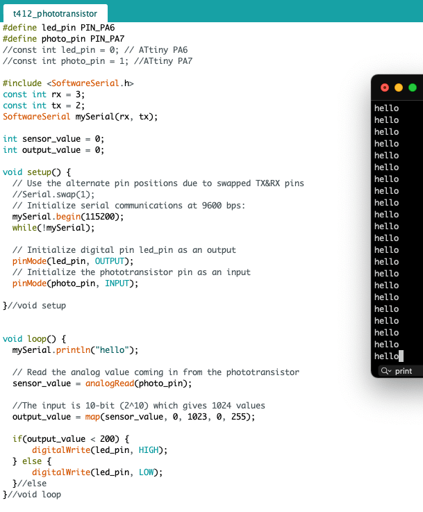
Using the Phototransistor
The final component on my board that I hadn’t incorporated through code yet was the phototransistor. The instruction slides from Henk had one example that used a sensor, which I used to write my starting code, together with the AnalogInOutSerial example from the Arduino website:
#define led_pin 0 // ATtiny PA6
#define photo_pin 1 //ATtiny PA7

int sensor_value = 0;

void setup() {
  // Initialize digital pin led_pin as an output
  pinMode(led_pin, OUTPUT);
  // Initialize the phototransistor pin as an input
  pinMode(photo_pin, INPUT);
}//void setup

void loop() {
  // Read the analog value coming in from the phototransistor
  // The input is 10-bit (2^10) which gives 1024 values -> between 0 - 1023
  sensor_value = analogRead(photo_pin);

  //If the sensor value is greater than 500, have the LED on
  if(sensor_value > 500) {
    digitalWrite(led_pin, HIGH);
  } else {
    digitalWrite(led_pin, LOW);
  }//else
}//void loop
I had no idea if the phototransistor would show a high number when it was dark of bright, but I grabbed a flashlight and could use my finger to block the phototransistor to test and see what would happen.
The first step was working, but I now wanted to make the LED blink: the brighter it became, the slower it should blink, while the darker it became, the faster it should blink until it was seemingly fully on when the phototransistor was blocked from light.
I first wanted to get a sense for the sensor values that were being output by the phototransistor. I therefore added a few Serial.print() statements to my code (I had also added a map function to go from the 0 - 1023 to a delay frequency that I could use to blink the LED with, which I called output_value).
The first time I uploaded the program with the print statements, the sensor and output values came flying by on my terminal screen so fast that I couldn’t even read them. Of course, I’d forgotten how fast that loop function must go. After a bit of searching I found an example to have the print statement only run every X milliseconds.
static const unsigned int refresh_interval = 1000; // milliseconds
static unsigned long last_refresh_time = 0;

#define led_pin 0 // ATtiny PA6
#define photo_pin 1 //ATtiny PA7
int sensor_value = 0;
int output_value = 0;

void setup() {
  // Initialize serial communications at 9600 bps:
  Serial.swap(1);
  Serial.begin(9600);
  while(!Serial);

  pinMode(led_pin, OUTPUT);
  pinMode(photo_pin, INPUT);
}//void setup

void loop() {
  // Read the analog value coming in from the phototransistor
  sensor_value = analogRead(photo_pin);
  // Map from 0 - 1023 to 1 - 1000
  output_value = map(sensor_value, 0, 1023, 1, 1000);

 if(millis() - last_refresh_time >= refresh_interval) {
   Serial.print(F("sensor: "));
   Serial.println(sensor_value);

   Serial.print(F("output: "));
   Serial.println(output_value);

   last_refresh_time += refresh_interval;
 }//if
}//void loop
I saw that the base level in my room was about 1000, which I found odd, since I also saw that “dark” was 1023 and I really wasn’t sitting in the near dark in my room. I did see that shining my flashlight on the sensor would bring the sensor value down, and if I pressed the flashlight almost on top of the sensor it could reach 0 (ignore the output lines in the image below for now):
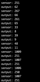
I still found it odd that my phototransistor was so heavily skewed that the section between normal lighting and dark was only ±23 steps, but between normal and very bright was the remaining 1000 (◎_◎;)
Perhaps I could use some easing function to “squeeze” the part from 0 - 1000 and “extend” the section between 1000 - 1023?
I used this website with visual examples to figure out what kind of easing I wanted. Something like an exponential or 5-order polynomial seemed good. I then found some examples of these easing functions (the latter written in C) that I could use for my own function.
I created another variable output_value_ease that would be the result from the easing between the 0 - 1000 interval. I also added this to the Serial.print() statements so I could check the eased value. However, when I tried to compile the code I kept on getting very vague errors about “text not fitting”.
I first thought that I was not handling my variables well, that my function was expecting an int in its arguments, but I was supplying a float, or that I was doing integer division (although I figured that shouldn’t give any errors).

But even when I removed the function and did the math within the general loop function it still didn’t solve anything. If I took out the lines with the new output_value_ease the code would compile though. I kept in struggling with that for a while, thinking it was errors in my math and usage of variable types.
Eventually I decided to search online on the one small section of text that seemed even remotely intelligible from the error statement '.text' will not fit in region 'text' during compile and was surprised to find results; apparently my program was too big! Really?! Had I already filled up my ATtiny with only ±40 lines of code? That I hadn’t expected at all, I had totally not been paying attention to the percentage value that the compiler shows (when it does compile) that is being taken up of the program storage space.
I searched for tips on how to reduce the size of my script in Arduino and found some useful tips on this page. Such as using #define led_pin 0 to set compiler constants instead of using int led_pin = 0;. Or to use int8_t to initialize an int that you know will stay within -128 and 128 (all of my int variables could get bigger sadly). Or to wrap any purely text print statement with F, such as Serial.print(F("sensor: ")). But most of the other tips I didn’t quite understand (*^▽^*)ゞ
While I was working on this I got the note from Quentin to not use SoftwareSerial anymore (which I was using till this point) and rewrote my prints to the default Serial, and finally my program wanted to compile again, pfew!
As a test I commented out all the Serial statements, and the storage space dropped from 80% to 51%. Damn, that was a lot of space taken up by Serial.
With the compilation errors gone, I had the easing function working on my board. It was blinking really fast as a default, would blink so fast that it seemed fully on when I placed my finger on the phototransistor, and blinked really slow when I shined my flashlight on it
#define led_pin 0 // ATtiny PA6
#define photo_pin 1 //ATtiny PA7
int sensor_value = 0;
int output_value = 0;
int output_value_ease = 0;

void setup() {
  pinMode(led_pin, OUTPUT);
  pinMode(photo_pin, INPUT);
}//void setup

void loop() {
  // Read the analog value coming in from the phototransistor
  sensor_value = analogRead(photo_pin);
  //Map to 1 - 1000 and then ease that value
  output_value = map(sensor_value, 0, 1023, 1, 1000);
  output_value_ease = easeOut(output_value, 1.0, 1000.0);

  // Blink the LED with a 2*output_value_ease timing
  blinkLED(output_value_ease);
}//void loop

//t = current value, b = start value, d = end value
int easeOut(int t, float b, float d) {
  float n = (t - b) / (d - b);
  return(int)(d - b) * (1.0 - n*n*n*n) + b;
}// int easeOut

// Make the LED blink with a delay of delay_time
void blinkLED(int delay_time) {
  digitalWrite(led_pin, HIGH);
  delay(delay_time);
  digitalWrite(led_pin, LOW);
  delay(delay_time);
}// void blink
Apologies for the crappy video below, I couldn’t point my phone camera directly at the board, because it messed up the blinking signal. I’ll explain a little further below why this happened.
Side Note | I noticed at some point that the my LED was still flashing when I kept my finger on it. I didn’t know why that had appeared all of a sudden. But later I found that when I slowed down the time during which the print statements were being run, that the flashing was also slower. Ah! So the print statements were interfering with the speed at which the loop could run. Commenting out my Serial statements fixed the issue indeed.
I kept on fiddling with my easing function, because I wanted the default blinking to go slower. But I couldn’t quite get it to work, the easing was getting quite extreme with a 7-th order polynomial. But I figured that it was good enough for now to at least take a video. But as soon as I pointed my phone’s camera at my board the blinking frequency became a bit erratic, jumping between different Hz. Coincidentally, around that time I was still chatting with Quentin, and told him about my phototransistor registering my room as almost completely dark, more as a joke. But he immediately asked if I perhaps didn’t have an infrared (IR) phototransistor. O no…. Did I….? ✖_✖
I thought I remembered that it was the only tiny box at the Waag that had the name phototransistor without also having IR in the name: Phototransistor NPN SMD PLCC-2, specifically with part number 365-1162-1-ND. I searched online for some information and found a PDF that put that specific part number in the infrared. Dammit!
I now understood the reason why my camera was messing with the blinking frequency. To focus, many camera’s use an infrared signal. Thus as soon as I pointed my camera at the board, the IR phototransistor would register a slight increase of the sensor value. And because I was using a high-order polynomial in my easing function to really stretch out the area around ±1000, it made a big difference in the decrease in speed at which the LED was blinking.
Using a Visible Light Phototransistor
I asked Henk if I was supposed to use an IR phototransistor, but he said it was supposed to be visible light.
Thus, back at the Waag after the weekend, I checked the wall with the little electronics boxes again, and saw that there was indeed one that said Phototransistor Visible 940nm. Hmmmm, perhaps I had been confused two weeks ago, because 940nm lies smack damn in the Infrared range (blue is ±450nm and red is 700nm). The box right next ot it even said Phototransistor IR 940nm.
But after an online search by Henk, looking at the parts list of the Fab Academy, he found that the Visible 940nm was indeed the one I was supposed to use. On the Digi-Key website you can see the datasheet of piece 1080-1380-1-ND, which shows the Range of Spectral Bandwidth to lie between 530nm - 1030nm, with the peak sensitivity at 940nm.
In all honesty, I wouldn’t say that was completely visible, because the shortest wavelength it can handle is green-ish, which is about halfway through the spectrum that the human eye can see. Whereas it does pick up a large portion of the IR spectrum. But ok, better something than nothing.
I used the heat gun to melt the soldering connections to my IR phototransistor, grabbing onto the phototransistor with tweezers and holding it up, supposedly letting gravity and heat do the rest. At first it just would not come off. My board was heating up, the paper sheet that was lying a little below where I was holding the board was turning brown even!
I stopped and looked at the tip of the heat gun and noticed that I was missing the small baffle that points the hot air into a thin stream, oops ✖‿✖
After putting the baffle on the heatgun and trying again, the board fell away from the phototransistor that I was holding after only a few seconds (such a difference!)
From the datasheet I had seen that the collector side was marked wit two green stripes, which was the side that should point towards the ATtiny.

I soldered on the new phototransistor, and set my computer and UPDI and FTDI up to program my board. This time the phototransistor reported values of around 400 - 600 as the base of the room (although this was at te Waag not at home), which was much more along the lines I had initially expected.
I deleted the original easing function, and instead created a second-order polynomial function (y = a*x^2 + b*x + c) using R that converts the 0 - 1023 range to a delay frequency range of 1000 - 1, clamped to 1 at 900
# Get a second-order polynomial fit trough
# these preferred points
x <- c(0, 500, 900)
y <- c(1000, 200, 1)

# Fit a regression curve
fit2 <- lm(y~poly(x,2,raw=TRUE)) #second degree polynomial

# Plot the results
xx <- seq(0,1000, length=50)
plot(x,y,pch=19,ylim=c(0,1500))
lines(xx, predict(fit2, data.frame(x=xx)), col="green")

# Get the coefficients
summary(fit2)
I added the coefficients of the polynomial to a new function called curveFit, and uploaded it to my board.
#define led_pin 0 // ATtiny PA6
#define photo_pin 1 //ATtiny PA7
int sensor_value = 0;
int output_value = 0;

void setup() {
  pinMode(led_pin, OUTPUT);
  pinMode(photo_pin, INPUT);
}//void setup

void loop() {
  // Read the analog value from the phototransistor, between 0 - 1023
  sensor_value = analogRead(photo_pin);

  // Map the sensor value to the range 1000 - 1
  // using a second-order polynomial
  output_value = curveFit(sensor_value);

  // Blink the LED with a 2*output_value timing
  blinkLED(max(output_value, 1));
}//void loop

int curveFit(int n) {
  return (int)(0.001225*n*n - 2.212*n + 1000);
}// int curveFit

// Make the LED blink with a delay of delay_time
void blinkLED(int delay_time) {
  digitalWrite(led_pin, HIGH);
  delay(delay_time);
  digitalWrite(led_pin, LOW);
  delay(delay_time);
}// void blink
And then my LED was showing some nice behavior with blinking while at base level, moving to seemingly full on when covered and blinking much slower when I shine a flashlight on it.
I did notice that IR (heat) had an effect on the phototransistor (which I see through the blink frequency of the LED). For example, there’s a difference if I use my finger to block the phototransistor (you can still see that it flashes), or a piece of cardboard (the LED seems always on). Or that it matters how close my arm is in general.
Not feeling quite right about the spectral range, I tested the sensor values again while back in my office, and damn, they were back at 1000 ( ̄ー ̄)
. I then checked the spectral range of that first phototransistor that was on my board, and saw that it was basically the same, running from about 450nm - 1100nm, with a peak at ±900nm. So now I’m just very confused about “visible light” phototransistors, not fully capturing visible light, but secretly adding a bulk of the IR range.
Programming With PlatformIO
Besides the Arduino IDE I also wanted to try a few other tools for doing embedded programming, one of which was the PlatformIO IDE. This is an extension for Visual Studio Code (VSC), which is my main code editor, so I was pleasantly surprised, and installed PlatformIO through the extensions tab from VSC.
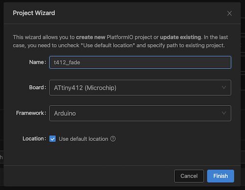
I followed the Quick start guide. You can open the PlatformIO Home tab by clicking on the tiny house icon that was now visible on the bottom info row of VSC.
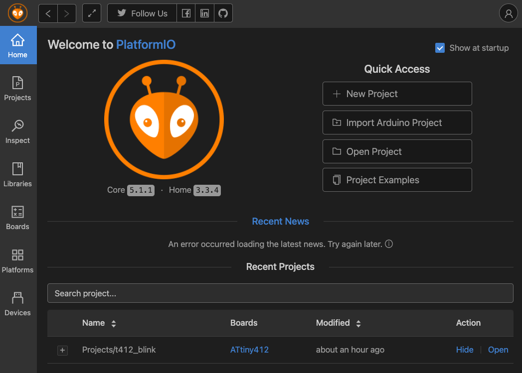
Which will bring you to a new tab from PlatformIO. Click on New Project, which opens a new window that asks for the project name, and the board and framework to use. It says by default that almost 900 boards are supported and thankfully the ATtiny412 is one of those.
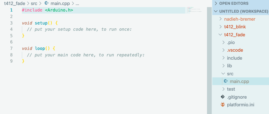
After it’s done with that (it might take a minute for the very first project ever), you should open up the main.cpp file in the src folder.
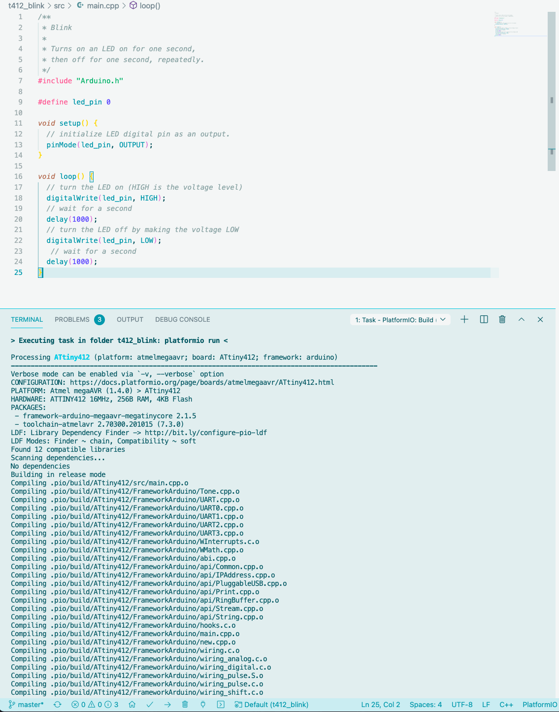
I copied the default “Blink” example from the PlatformIO Quick start, only changing the LED_BUILTIN variable to #define led_pin 0. I clicked the little “check mark” icon to compile (or Build as it’s named here) the program, and that all went smoothly.
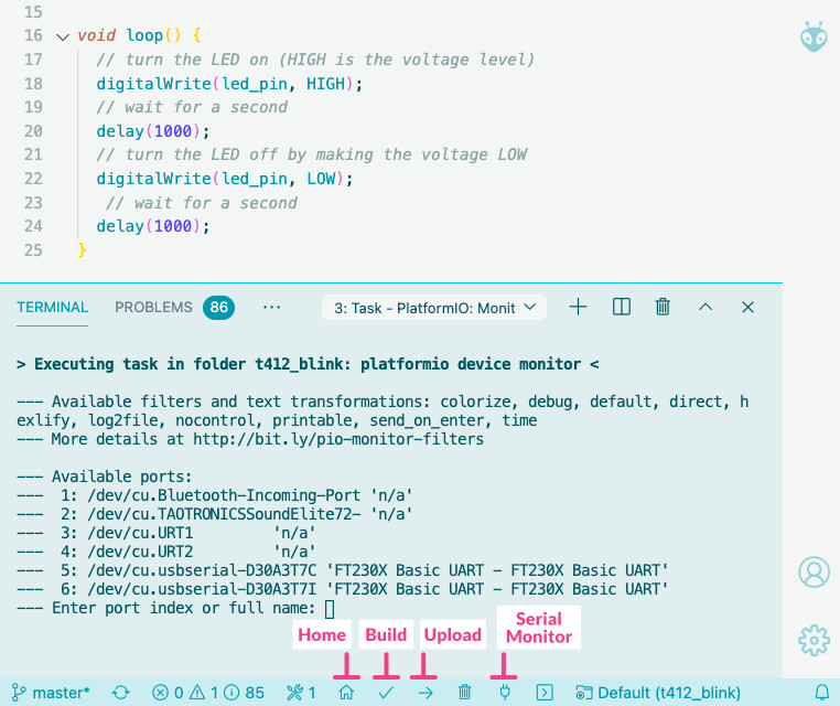
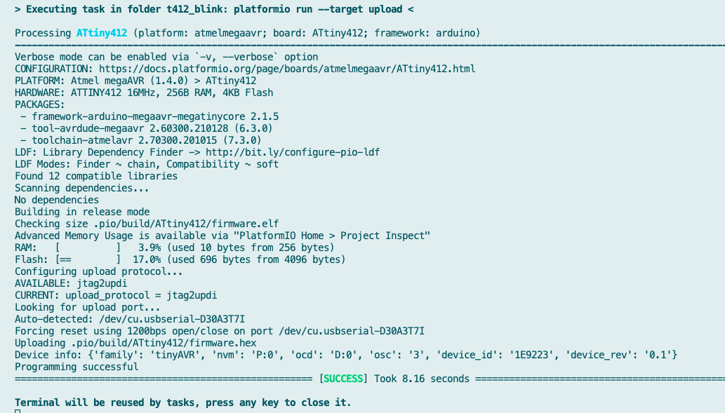
I figured I might as well click the Upload icon next (the “right-arrow” icon) and see what happens. This time I wasn’t so lucky, and got an error:
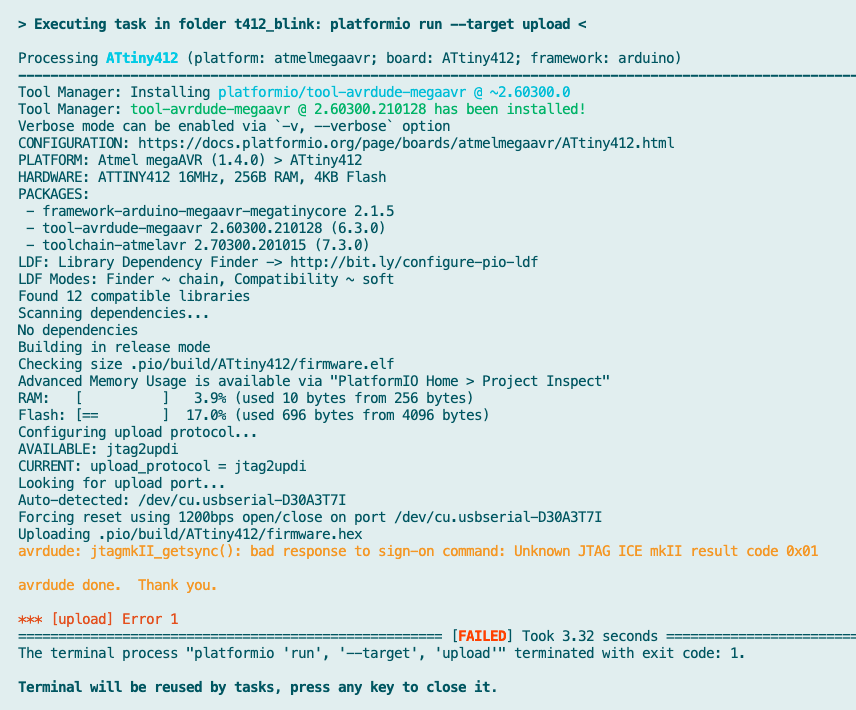
I inspected the log and the start seemed good indeed, but then I was confused to read jtag2updi upload protocol. I was expecting to see something about pyupdi. I did notice that it was using my UPDI in the Auto-detect: /dev/cu.usbserial-D30A3T7I line, whereas I never actually selected my port I realized.
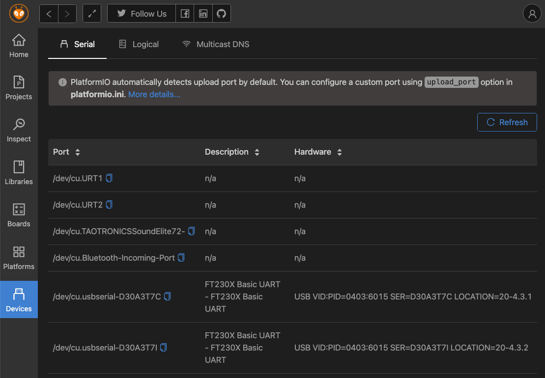
I read a little into this, and learned that PlatformIO will try and select the correct port for you. I found that you can see a list of the available ports/devices from the PlatformIO home page by clicking on the Devices tab along the left:
But since this was going correctly, I had to look elsewhere for my upload error.
I found the Atmel megaAVR plugin/library for PlatformIO, which led me to its documentation within the PlatformIO docs. And there I found a section on “Upload using pyupdi”. It seemed that I had to use a custom upload_command in my project’s platform.ini file.
I thus opened the platform.ini file in VSC and added the upload_speed, upload_flags, and upload_command lines to it:
[env:ATtiny412]
platform = atmelmegaavr
board = ATtiny412
framework = arduino
upload_speed = 115200
upload_flags =
    -d
    tiny412
    -c
    $UPLOAD_PORT
    -b
    $UPLOAD_SPEED
upload_command = pyupdi $UPLOAD_FLAGS -f $SOURCE
I really wasn’t sure if that would be enough. I pressed the Upload button again, and it worked, ending with a SUCCESS statement and blinking LED on my board (๑•̀ㅂ•́)ง✧
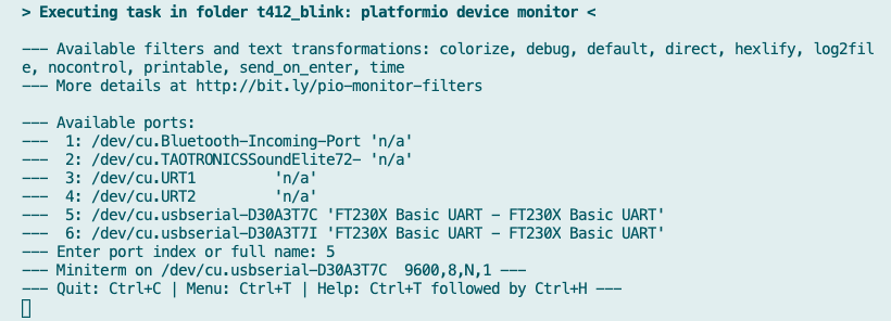
Note | By pressing the little “electrical plug” icon (the Serial Monitor) brings up the terminal window in VSC where it tells you the available ports and by selecting a number it will open that port for you, really handy!
Note | I found that there is a dedicated page for each AVR chip on the PlatformIO docs, such as the ATtiny412
Seeing that I could get PlatformIO working, I left it at that, choosing to remain with the Arduino IDE for this week.
Programming With Python
I also took a quick look at using MicroPython or CircuitPython (which is based on MicroPython). However, I quickly found this line on the MicroPython website: “Yet it is compact enough to fit and run within just 256K of code space and 16K of RAM”. However, our ATtiny412 has 4KB of Flash and only 256B of SRAM. I therefore understood it as being not possible to use these python methods of programming my board, and let them be.
Maybe if I choose to use a ESP8266 or ESP32 development board in the future I could look into this again (using this, this, and this tutorial perhaps).
The ATtiny412 Datasheet
Part of our individual assignment this week was to read/skim through the entire datasheet of the microcontroller that we’re using on our boards, so we know what kind of data can be found in it. The datasheet of the ATtiny412 is almost 600 pages, and I’ve understood that 1000 pages isn’t that odd to have for other microcontrollers, so I guess I should consider myself lucky (◍•﹏•)
The first page of the datasheet lists the technical specifications of the tinyAVR 1-series, but I have to admit that the relevance of the specs still eludes me for most of the lines.
Section 2 shows a table with the Peripheral summary, where I know at least some of the words, such as there being 1 USART, but also an SPI and I2C connections, six ADC and one DAC connection.
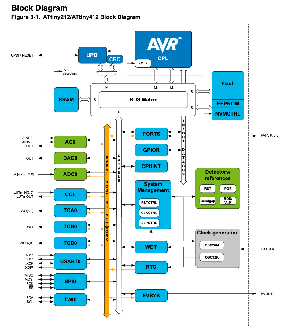
The Block Diagram in section 3 gives a peek inside the microcontroller. I’m starting to read/recognize some parts in here now, but it’s still mostly an unknown to me.
Section 4 is the Pinout which I’ve referenced before already. I’m not quite sure why this pinout image is so sparse with the pin info that it gives. But at least they do seem to give a lot more info on what functions each pin can do in the Multiplexed Signals table of section 5, which is the table that made me realize that we have our TX and RX pins mapped to their alternate positions.
Section 6 gives an expanded overview of the different types of memories; Flash, SRAM and EEPROM. These can be separated into two types: Volatile memory where the stored data is lost when it loses power and Non-Volatile memory where it remembers the information even if the power to it is turned off. SRAM is volatile, while Flash and EEPROM are non-volatile.
The Flash memory is 4KB and is the space available for the storage of the program I upload through the UPDI. It seems that part of this 4KB is taken up by the bootloader, while the rest gets used by the actual code and the “application data”.
The EEPROM Memory, Electrically Erasable Programmable Read-Only Memory, of 128 bytes is, I believe, used to store small amounts of data, such as the states of certain input and output devices connected to the MC that need to be stored for longer periods of time (e.g. it needs to be remembered for when the board powers up again for example).
The SRAM Data Memory, which stands for Static Random Access Memory, is 256 bytes. I believe this is the memory that is used to hold the variables and functions in memory while the chip executes its tasks.
I found this explanation and this video on the differences between the types of memory to be helpful.
The rest of section 6 goes deeper into the specifics of these types of memories, which was beyond my knowledge at this point.
Section 7 shows a table of the “Peripheral Module Address Map”, with the base address for each peripheral. However, I don’t know what a base address is though, nor an Interrupt Flag…

Section 8 goes into the AVR CPU, giving the technical specs (e.g. it’s 8-bit, and uses a Harvard architecture that separates program and data memory). The docs say that “The CPU is able to access memories, perform calculations, control peripherals, and execute instructions in the program memory” and “While one instruction is being executed, the next instruction is pre-fetched from the program memory. This enables instructions to be executed on every clock cycle."
The CPU has an ALU, Arithmetic Logic Unit which does the math and logic operations. Thanks to a Hardware Multiplier it can multiply two 8-bit numbers into a 16-bit result (section 8.4.1), and it also goes into Stacks and Registers.
Section 9 goes into the Non Volatile Memory Controller (NVMCTRL), the interface between the device, the Flash, and the EEPROM. From the docs: “The Flash and EEPROM are reprogrammable memory blocks that retain their values even when not powered. The Flash is mainly used for program storage, but can also be used for data storage. The EEPROM is used for data storage and can be programmed while the CPU is running the program from the Flash." The section then goes into the Flash and EEPROM memories again, talking about write and erase commands.
Section 10 is about the Clock Controller (CLKCTRL) where the ATtiny412 has a 20Mhz oscillator (and also a 32KHz Ultra Low Power oscillator), however it can also handle an external clock. The Clock Controller peripheral controls, distributes, and pre-scales the clock signals from the available oscillators. It supports internal and external clock sources. There are several types of clocks I believe, with a main clock, CLK_MAIN that is used by the CPU, RAM, Flash and all peripherals connected to IO?
Section 11 goes into the Sleep Controller (SLPCTRL) where there are three sleep modes; Idle, Standby and Power Down (the remaining mode is the Active mode). The docs explain it is “Sleep modes are used to shut down peripherals and clock domains in the device in order to save power. The Sleep Controller controls and handles the transitions between active mode and sleep mode." Depending on the type of sleep mode different types of peripherals and clocks are turned off. Interrupts are used to wake up again, but if there are no interrupts enabled when going to sleep, the device cannot wake up again. Only a reset will allow it to continue operation.
During Idle mode the CPU stops executing code, but no peripherals are disabled and all interrupt sources can wake it up. In the Standby mode, the user can configure any peripheral to be enabled or not, giving the user control over the power consumptions (see 11.3.2.1 for the interrupt options). Finally, in Power Down mode only the WDT and PIT are active and the only wake-up sources are the pin change interrupt and TWI address match (whatever those may mean).

Section 12 is the Reset Controller (RSTCTRL) which can reset the device to its initial state. The sources for doing such a reset are the:
- Power supply Reset sources - caused by changes in the power supply voltage: Brownout Detect (BOD), Power On Reset (POR)
- User Reset sources - issued by the application, debug operations or by pin changes: External Reset pin (RESET), Watchdog Reset (WDT), Software Reset (SW) and UPDI Reset
Where I think that I’ve only used the UPDI Reset. The start of this section goes deeper into what the different kinds of reset sources are.
Section 13 goes into the CPU Interrupt Controller (CPUINT). The datasheet explains it as “An interrupt request signals a change of state inside a peripheral, and can be used to alter program execution. Peripherals can have one or more interrupts, and all are individually enabled and configured. When an interrupt is enabled and configured, it will generate an interrupt request when the interrupt condition occurs." The CPUINT also looks at the priority level of incoming interrupts and decides to act or keep them pending, depending on how it compares to any ongoing interrupts.
Section 14 explains the Event System (EVSYS), which allows a change in one peripheral (the Event Generator) to trigger actions in other peripherals through Event channels without using the CPU.
In Section 15 there is the Port Multiplexer (PORTMUX), which I tried to understand while testing my board two weeks ago, and seeing the TX/RX port swap. I do understand (more about) the concept of port multiplexing now, where you have the option to change the functionality of pins, such as using alternative pins for the TX and RX.
Section 16 is about the I/O Pin Configuration, which are the six General Purpose Input and Output (GPIO) pins. But I have to admit that I didn’t understand much about what was being explained in the overview about this.
Section 17 explains the Brownout Detector (BOD) that I come by in section 12 before as a way to cause a reset. The Brownout detection monitors the power supply to avoid operation below a programmable level. The threshold defines when to generate a reset.
Section 18 is the Voltage Reference (VREF) which provides an accurate, low noise, constant output voltage that is used by several peripherals (the default reference voltages are 0.55V). I couldn’t quite understand why to use this though (even after searching online for it, none of it was noob enough).
Section 19 goes into the Watchdog Timer (WDT) which is also a reset source. “It allows to recover from situations such as runaway or deadlocked code, by issuing a reset. When enabled, the WDT is a constantly running timer configured to a predefined timeout period. If the WDT is not reset within the timeout period, it will issue a System Reset. […] When enabled, the WDT will run in active mode and all sleep modes."
The next three chapters go into a few different types of timers/counter, with section 20 about the TCA, a 16-bit PWM Timer/Counter type A. A TCA consists of a base counter and a set of compare channels: “The base counter can be used to count clock cycles or events […] The compare channels can be used together with the base counter to do compare match control, frequency generation, and pulse width waveform modulation." And there are some explanations in this section about different types of PWM generation. Section 21 is about TCB, the type B timer/counter which includes frequency and waveform generation. The TCB consists of a base counter and control logic which can be set in one of eight different modes, each mode providing unique functionality, that are explains in section 21.3.3.1. Finally there is the TCD, the type D timer/counter and is “a high performance waveform controller that consists of an asynchronous counter, a pre-scaler, compare logic, capture logic, and control logic. The purpose of the TCD is to control power applications like LED, motor control, H-bridge and power converters."
Section 23 is about the Real Time Counter (RTC), which I didn’t understand.
Section 24 is about the USART or Universal Synchronous and Asynchronous Receiver and Transmitter, the connection that I’ve been using to receive and transmit (serial) information with to my board via that TX and RX pins. Communication is frame based and a serial frame consists of:
- 1 start bit
- 5, 6, 7, 8, or 9 data bits
- Parity bit: even, odd, or none
- 1 or 2 stop bits
It can apparently also be set to one-wire mode, where the transmitter and receiver share the same TxD pin. The rest of the section goes into elaborate detail.
Section 25 is the Serial Peripheral Interface or SPI and “is a high-speed synchronous data transfer interface using three or four pins. It allows full duplex communication between an AVR device and peripheral devices or between several microcontrollers. The SPI peripheral can be configured as either Master or Slave. The master initiates and controls all data transactions.". I haven’t worked with SPI before I believe, but that might still come in the next weeks, where I might learn more about the MISO, MOSI, SCK and SS ports.
Yet another communication interface is described in section 26: the Two Wire Interface (TWI), which is a bidirectional, two-wire communication interface, and is I2C compatible. The latter being another term that I’ve been hearing here and there and think I’ll learn more about in upcoming weeks. This section also goes into extreme detail how TWI works.
And then for something completely different in section 27 with the Cyclic Redundancy Check Memory Scan (CRCSCAN), which can be used to detect errors in program memory.
Section 28 is about Configurable Custom Logic (CCL), which is a programmable logic peripheral, which I believe could be a powerful way to bypass the CPU for doing logic tasks?
Section 29 goes into the Analog Comparator or AC which compares the voltage levels on two inputs and gives a digital output based on this comparison, of which the ATtiny412 has one output pin PA3 (and PA6 and PA7 should be used as the input pins?)?
All pins besides the VCC and GND pins are capable of Analog to Digital Converter (ADC) which is explained in section 30, with a resolution of 10-bit (and a sampling rate up to 115ksps).
In section 31 we read about the inverse direction, the Digital to Analog Converter (DAC, of which the ATtiny412 has one pin (PA6), of 8-bit resolution capable of converting 350,000 samples per second (350ksps).
Section 32 is about the UPDI or Unified Program and Debug Interface. The process / interface that I’ve been using to program the ATtiny412. There is some really extensive documentation in this section that goes way beyond my knowledge.
And with that I think the datasheet had explained all the peripherals and goes into the Electrical Characteristics in section 33. Such as the minimum and maximum of the power supply and currents, at what frequencies the clock can run depending on the voltage and temperature, what the power consumption is at different clock frequencies and voltages, and much more having to do with voltages and frequencies when using any of the peripherals.
In section 34 we finally see some charts! Such as the current versus the frequency for different voltage levels. But there are many more charts comparing current, voltage, frequency and temperature in different ways, and for different peripherals. This seems like info useful for the really expert readers.
The remaining chapters go into ordering information, packaging, with section 36 finally giving an image of the actual ATtiny with top, side and top-side views. But also recommendations for the footprint settings I believe.
And Arithmetic and Logic Instructions in section 37 which sounds interesting, but where you need some background knowledge to make sense of.
A kind of glossary in sections 38 and 39 and that’s about it. Finally!
Programming Other Boards
During the instruction day at the Waag, we got to play and program several other boards that Henk had available. I didn’t get to program them all, but let me describe the boards that were there. For the programming, I teamed up with Loes.
Arduino Boards
Possibly the most well known brand in boards (although there’s Raspberry Pi too of course). Over the years many different boards have been created, in different sizes. You can program an Arduino board without using any kind of extra board libraries within the Arduino IDE because all these boards are pre-installed.
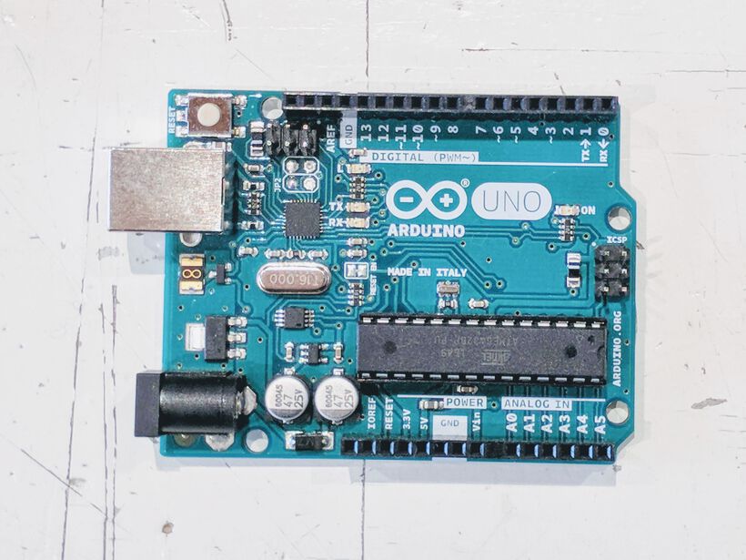
Arduino UNO
The Arduino UNO is a great board to getting started with electronics and programming a board. Its microcontroller is an ATmega328P, which has 32 KB of memory (with 0.5 KB occupied by the bootloader). You can find a wealth of useful information about this board on the Arduino website.
Some of the most important components of the board are:
- 14 digital input/output pins, labelled 0 - 13
- They all operate at 5 volts
- Of these 6 can be used as 8-bit PWM outputs, those with the
~mark next to them: 3, 5, 6, 9, 10, and 11 - Each pin can provide or receive 20 mA
- Each pin has an internal pull-up resistor of 20-50k Ω (disconnected by default)
- Pins 0 and 1 are used for RX and TX respectively
- 6 analog inputs, labelled A0 - A5
- They provide 10 bits of resolution
- a 16 MHz ceramic resonator
- a built-in LED on pin 13
- a USB connection, type B strangely
- a power jack
- two ICSP (In-Circuit Serial Programming) headers (the two connectors with 6 pins pointing upward)
- a reset button
An extended overview of the pinout can be found here. To go into a bit more detail about the power pins, taken from the Arduino website:
- Vin | The input voltage to the Arduino board when it’s using an external power source (as opposed to 5 volts from the USB connection or other regulated power source). You can supply voltage through this pin, or, if supplying voltage via the power jack, access it through this pin.
- 5V | This pin outputs a regulated 5V from the regulator on the board. The board can be supplied with power either from the DC power jack (7 - 12V), the USB connector (5V), or the VIN pin of the board (7-12V). Supplying voltage via the 5V or 3.3V pins bypasses the regulator, and can damage your board. We don’t advise it.
- 3V3 | A 3.3 volt supply generated by the on-board regulator. Maximum current drawn is 50 mA.
You use the USB connection to both power the board via a laptop, but also to program it. However, you can use the jack connection for external power as well. The recommended range is 7 to 12 volts.
The Arduino Uno comes with a bootloader installed so we don’t have to use an external hardware programmer to upload new code to it (which I believe means we don’t need a UPDI to program it?). But you can by-pass this bootloader by using the ICSP connection.
I loved playing with the different Arduino’s during this afternoon so much, that I ordered an Arduino Uno that very evening! (^ᗨ^) (although I actually never got to play with the Uno during the day).
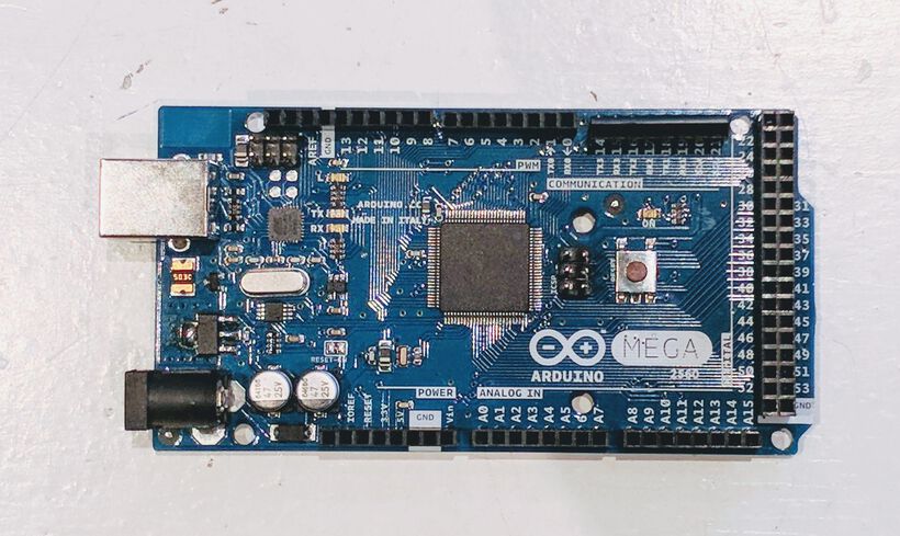
Arduino Mega
I think the Waag has the original version of the Arduino Mega, but let me talk about the Arduino Mega 2560 Rev 3, because that’s the newest one at this moment. The microcontroller on the Mega is a ATmega2560 with a memory of 256 KB. An extended overview of the pinout can be found here.
- 54 digital input/output pins!
- They all operate at 5 volts
- Of these 15 can be used as 8-bit PWM outputs, those with the
~mark next to them: 2 to 13 and 44 to 46 - Each pin can provide or receive 20 mA
- 4 UARTS: Serial pins: 0 (RX) and 1 (TX) | 19 (RX) and 18 (TX) | 17 (RX) and 16 (TX) | 15 (RX) and 14 (TX)
- 16 analog inputs, labelled A0 - A15
- They provide 10 bits of resolution
- a 16 MHz crystal oscillator
- a USB connection, type B
- a power jack
- an ICSP header
- a reset button
As with the Arduino Uno, this board can be powered via the USB or the jack connection, and programmed via the USB (or ICSP header to bypass the bootloader). Some other things are also the same for the Arduino Mega and the Arduino Uno, such as the power pins and supply, so please check the Arduino Uno section for more info. And you can find more info about the Arduino Mega on the Arduino website.
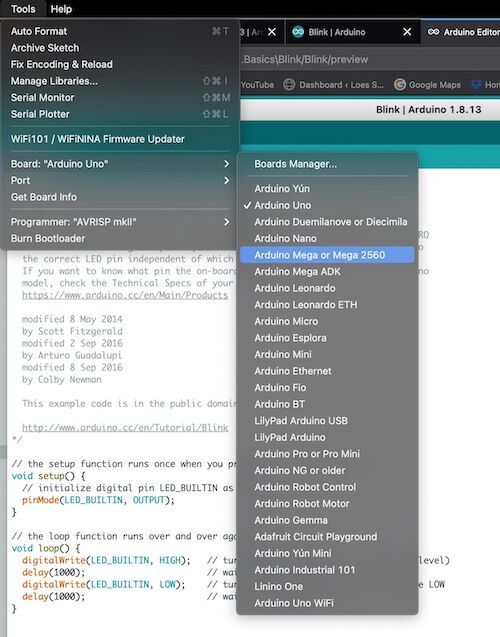
Loes and I picked up the Arduino Mega as our first board to play with. Using a USB B cable to connect it to Loes' Mac. Opened up the Arduino IDE, selected the Blink example. This uses the LED_BUILTIN variable for the internal LED pin, so you don’t have to figure out the pin number.
That all went smoothly, so we wanted to try with an external LED. The Arduino website mentions that you need to attach a resistor to the LED. However, we’d seen Henk push an LED into the GND and another pin during the instructions that morning, so we did the same (perhaps the pins internal pullup resistor gets turned on automatically in that case?)
We switched from the LED_BUILTIN variable to setting our own int led_pin = 10; and voila, the LED turned on after compiling and uploading the program.

We copied the Fading example next, and played a little with the delay values and the incremental values of the two loop functions to see how it would affect the timing of the fade.
Next, we wanted to play with a breadboard! We’d seen Henk set up a simple example that morning, and it seemed like fun. We learned that the 5 pins per row (there are two sections of five) are interconnected. We thus plugged in a cable from GND to row 29, pushed the LED with one leg into that row as well and another leg in the row 28, and finally a pin going from row 28 back to the Arduino pin 10. I did put in the LED the wrong way around the first time, but a quick switch and the LED started fading (ノ◕ヮ◕)ノ*:・゚✧
That went so well, that we figured we wanted to expand on the fade and add another LED that would fade in reverse (go on while the red one went off and vice versa). We plugged in a green LED into rows 24 and 25, added another wire from row 29 to row 25 for the GND and added one final wire to connect the LED from row 24 to the Arduino pin 9.
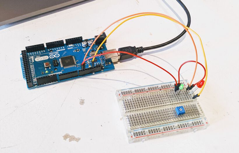
And adjusted our code to include the green LED:
const int led_pin_red = 10;
const int led_pin_green = 9;
const int max_value = 100;

void setup() {
    //nothing
}

void loop() {
    //fade from 0 to max_value in increments of 5
    for(int fade_value = 0; fade_value <= max_value; fade_value += 5) {
        analogWrite(led_pin_red, max_value - fade_value);
        analogWrite(led_pin_green, fade_value);
        delay(20);
    }//for

    //fade from max_value to 0 in increments of 5
    for(int fade_value = max_value; fade_value >= 0; fade_value -= 5) {
        analogWrite(led_pin_red, max_value - fade_value);
        analogWrite(led_pin_green, fade_value);
        delay(20);
    }//for
}//void loop
Which made our green and red LED cross fade from each other:
At that point we felt it was time to try some other boards as well.
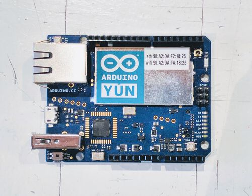
Arduino YUN
I didn’t get to play with the Arduino Yún, which is the original version. Because there is now a Rev 2 version, let me go into the technical aspects of the updated one. It runs on a ATmega32U4, same as the old version. The special thing about the Yun is that it has loads of connections, including Wi-fi, and it has a second microprocessor (the Atheros AR9331) that runs on Linux with python preinstalled. You can find an extensive pinout of the board here.
Here are some of the most important components:
- 14 digital input/output pins
- Of these 7 can be used as 8-bit PWM outputs, those with the
~mark next to them - Each pin can provide or receive 40 mA
- Pins 0 and 1 are used for RX and TX respectively
- Of these 7 can be used as 8-bit PWM outputs, those with the
- 6 analog inputs, labelled A0 - A6
- a 16 MHz crystal oscillator
- a standard USB connection
- a micro USB connection
- an ethernet connection
- a microSD slot for external storage
- three reset buttons; for the WiFi, the Arduino chip and the Linux chip
For more information, see the Arduino website.
Arduino Nano
Henk said that he had the Arduino Mini, but when we investigated photos of the Mini we noticed that the one we were holding looked slightly different, and found that we had in fact and Arduino Nano.
And actually, after investigating for this documentation, I think that it’s a clone of the Arduino Nano V3, because it looks exactly like this one, whereas the original V3 looks just a bit different. They both have a ATmega328 microcontroller with 32 KB of memory though, just like the Arduino Uno. I think this pinout schema would still be the one to apply to the V3? Some other facts about the Nano:
- 14 digital input/output pins
- Of these 6 can be used as PWM outputs
- Each pin can provide or receive 40 mA
- Pins 0 and 1 are used for RX and TX respectively
- 8 analog inputs, labelled as A0 - A7
- a 16 MHz crystal oscillator
- a mini-USB connection
- a reset button
This is the cheapest Arduino PCB and really tiny, making it more ideal than the Uno in case there isn’t a lot of space available in the project you’re building. It’s size also makes it fit onto a breadboard if you use pin headers.
Loes and I did experiment with this board for a bit. We plugged the Mini-B USB cable into the laptop, selected the Arduino Nano from the Boards, and wanted to upload the standard “Blink” script, but it failed the first time.

After a short online search, I found a “Getting started with the Arduino Nano” tutorial, that mentioned that for old boards you had to select the ATmega328P (Old Bootloader) as the Processor. We tried this, and it worked, the build-in LED started blinking. Ok, so we had an old Arduino Nano it seemed.
We next looped the wires from the breadboard that we had set-up already from playing with the Arduino Mega through the holes of the GND and two of the digital pins, labelled D9 and D10, both of which can do PWM (but that was a happy coincidence, because we didn’t understand PWM enough at that time (*^▽^*)ゞ ), uploaded the fading program, and the two LEDs started fading again.
ESP Boards
There were two boards with ESP microcontrollers that were lying on the table for us to play with, the ESP8266 and its newer iterations the ESP32. These both have WiFi, whereas the ESP32 also has Bluetooth.
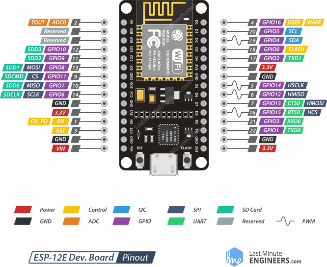
NodeMCU ESP8266
The NodeMCU is a development board that holds the ESP8266 microchip having the Tensilica Xtensa® 32-bit LX106 RISC microprocessor. There is 128 KB of memory.

- Operates at 3.3V
- 17 digital input/output pins, labelled as D0 - D8, RX, TX, CLK, CMD, SD0 - SD3
- Of these 4 can be used as PWM, being D2, D5, D6 and D8
- Each can be configured to be an internal pull-up or pull-down resistor
- 1 analog input, labelled as A0
- 2 UART interfaces
- a micro-USB connection
Here is an overview of the pinout, from LastMinuteEngineers.com
The ESP8266 can both connect to a WiFi network and also set up a network of its own, allowing other devices to connect directly to it.
You can program and power the ESP8266 NodeMCU via the micro-USB connector. Alternatively, if you have a 5V voltage source, the VIN pin can be used to directly supply the ESP8266 and its peripherals.
This website has a lot more technical specifications and explanations about the NodeMCU ESP8266.
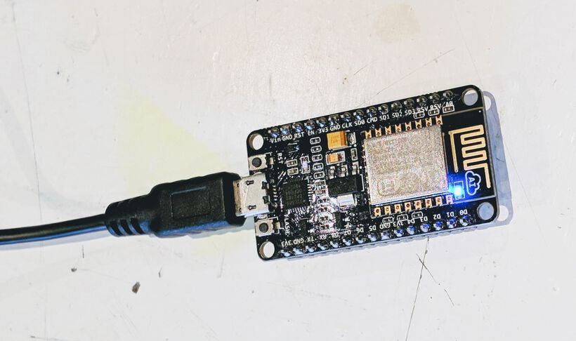
After playing with two Arduino’s we were ready to try a different type of board and picked the NodeMCU ESP8266.
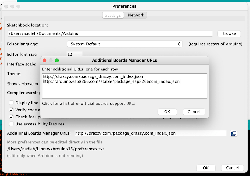
This board wasn’t in the available boards of the Arduino IDE, but we found a tutorial on how to install the ESP8266 to the boards. From the Arduino Preferences add http://arduino.esp8266.com/stable/package_esp8266com_index.json to the Board Manager URLs
Next, go to Tools -> Board -> Board Manager. In the new window search for ESP8266 and install ESP8266 by ESP8266 Community.
Once that is installed, there should now be another option to choose from under Board, the ESP8266 Boards. Loes and I noticed that there is a NodeMCU 0.9 and NodeMCU 1.0 option available. A quick image search and comparing to the one on our desk later and we knew that ours was the 1.0 version.
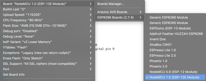
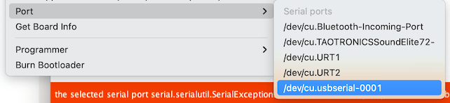
With the correct board selected, we also selected the Port of the NodeMCU, labelled as /dev/cu.usbserial-0001.
However, when trying to upload the simple program from the tutorial to make the internal LED blink, we ran into an error about pyserial or esptool directories not found. I eventually found a solution to this on the Arduino forum. Having to replace some very specific lines within the list_ports_osx.py file:
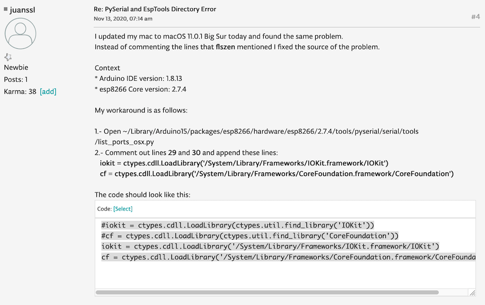
We didn’t expect that to work in one go, but it actually did, and the internal LED started blinking!
Next, we plugged the header pins underneath the NodeMCU into the breadboard and connected the wires the GND and two Dx rows (randomly choose for D2 and D7, which had pin numbers 13 and 4). Strangely though pin 13 does not have PWM according to the pinout schema from above, but when we loaded the Fade program, both the red and green LED were fading nicely.
Loes did have to keep her finger pressed on the NodeMCU board, otherwise the contact with the breadboard was lost.
ESP82 AI-Thinker
The other ESP board was an ESP32-CAM AI-Thinker. This has a tiny camera, a microSD card slot, and a very bright on-board LED. The ESP32 has WiFi (like the ESP8266), but the ESP32 also has Bluetooth. There is 512 KB of memory.
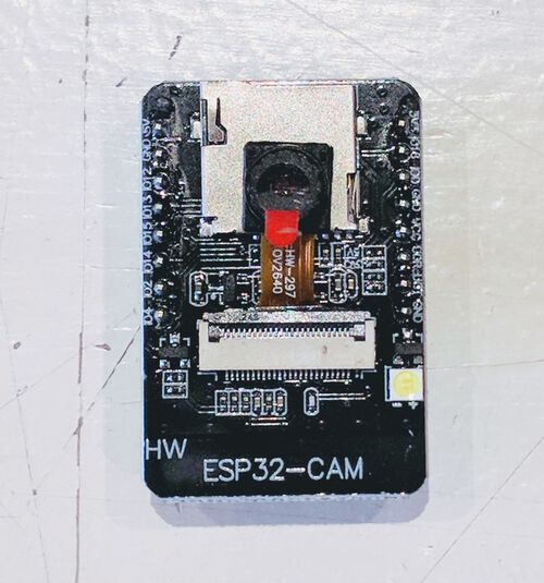
- 10 digital input/output pins
- 1 UART interface, labelled as U0R and U0T
- a micro-SD card slot
- a tiny camera
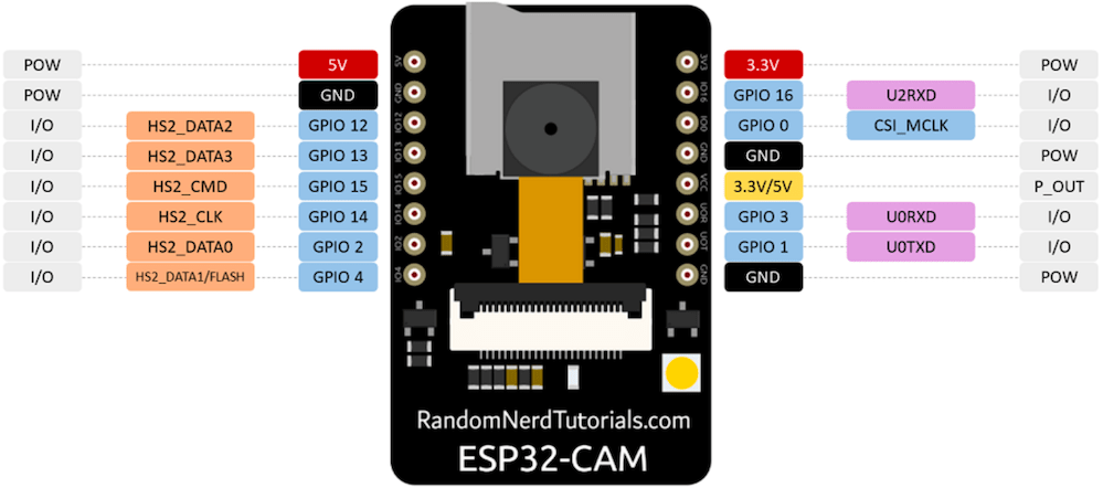
This page on the ESP32-CAM AI Thinker has a lot of technical information, including the pinout:
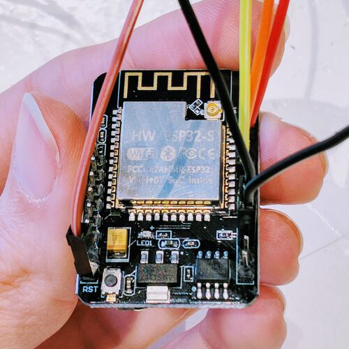
I found this tutorial to program the ESP32-CAM with the Arduino IDE. It has a very handy example on how the ESP32 needs to be connected to an FTDI (it doesn’t have a USB connection of its own):
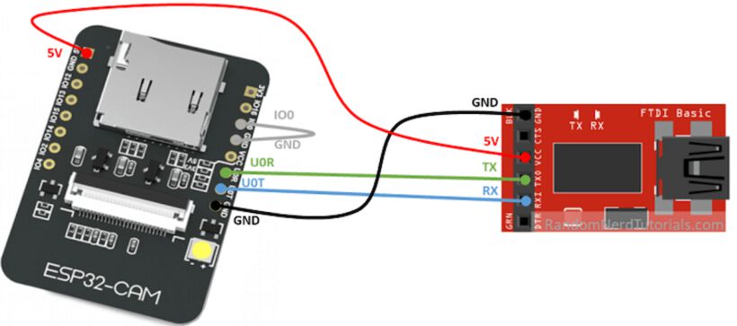
And you might miss it, but the GPIO 0 pin needs to be connected the a GND pin as well. Only when this connection is made does the ESP32 go into flashing mode and you can upload code to the board.
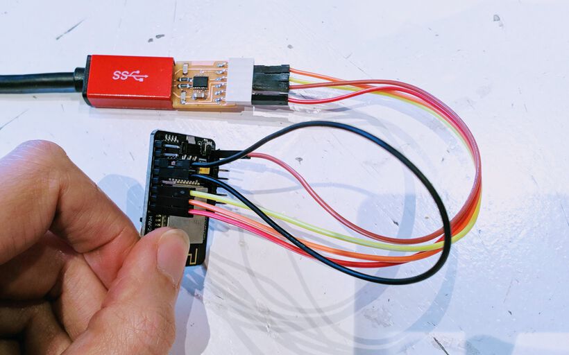
I carefully recreated the setup from the image, using the FTDI board schematic to check what each pin represented. Making sure to connect the GND pins first, and to not connect the 5V pin to GND!
To install the ESP32 library in the Arduino IDE, follow the same steps as for any library: Go to the Arduino IDE Preferences and in the Board Manager urls add https://dl.espressif.com/dl/package_esp32_index.json. Then under Tools -> Board -> Board Manager install ESP32 by Espressif Systems
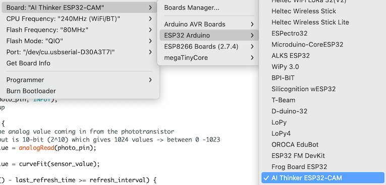
I could then select the AI Thinker ESP32-CAM under Boards from the very long list of ESP32 boards.
Don’t forget to set the Port to my FTDI, since I was now using the FTDI to upload a program to the ESP32.
I started with an empty program, just to make sure that I could make it upload. At first I got an error that Resource busy: '/dev/cu.usbserial-D30A3T7C'. O right! I still had the screen command running. I closed it (with CTRL+a + CTRL+\) and uploaded my program again.
This time I saw that a connection was trying to be made with the board and saw a bunch of ....._____....._____ slowly appear on my screen. After waiting for a while an error appeared about a time out:
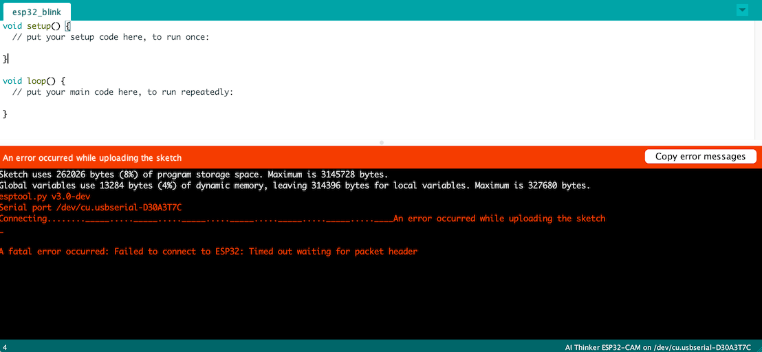
I really should’ve kept on reading the tutorial, because the next sentence was literally “When you start to see some dots on the debugging window, press the on-board RST button." (*^▽^*)ゞ
I uploaded the code again, and pressed the tiny RST button on the back when I saw the ....____ pattern appear. A second later the connection was made and my empty program was loaded onto the board.
I made sure to read the rest of the tutorial, but thankfully it was only one more step after the program was done uploading: Disconnect the GPIO 0 pin from GND and press the RST button to run the new code.
With my empty program I didn’t know if that last step went ok, so I connected the GPIO 0 pin to GND again and opened the default “blink” example. I found online that the flashlight LED is connected to pin GPIO 4, I thus set #define led_pin 4 and uploaded the program.
I was watching the LED from close by, not considering the giant size of this LED, because when it started flashing, it was bright and I got blinded for a second (O_O)

After taking a photo and video I quickly uploaded the empty program again, just to make the flashing stop ✖‿✖
Only then did I find that the tiny built-in LED was set to port GPIO 33.
I had heard Loes talking about a WiFi scan example that seemed interesting to try. Within the Arduino IDE I opened the Examples -> WiFi -> WiFiScan example, and without changing anything I uploaded it to the board.
This time I could use the Serial Monitor from the Arduino IDE because I was both uploading my program to the ESP32 with the FTDI and listening to incoming messages. I saw that the Waag has a lot of wifi signals in the neighborhood!

Finally, I wanted to try and access the camera. I found a tutorial that walked me through the (few) required steps. Such as selecting the Examples -> ESP32 -> Camera -> CameraWebServer. Next, I had to input the name and password of the wifi I was currently on at the Waag, and finally, I had to select the correct camera model by commenting the line with #define CAMERE_MODEL_WROVER_KIT and uncommenting #define CAMERA_MODEL_AI_THINKER.
I uploaded the code, and in the Serial Monitor that I still had open, I saw that the camera was ready, and I could access it from a certain IP address.
The address did work, and I was seeing images (after pressing Start Stream), but there was definitely something still not set up correctly with it σ_σ
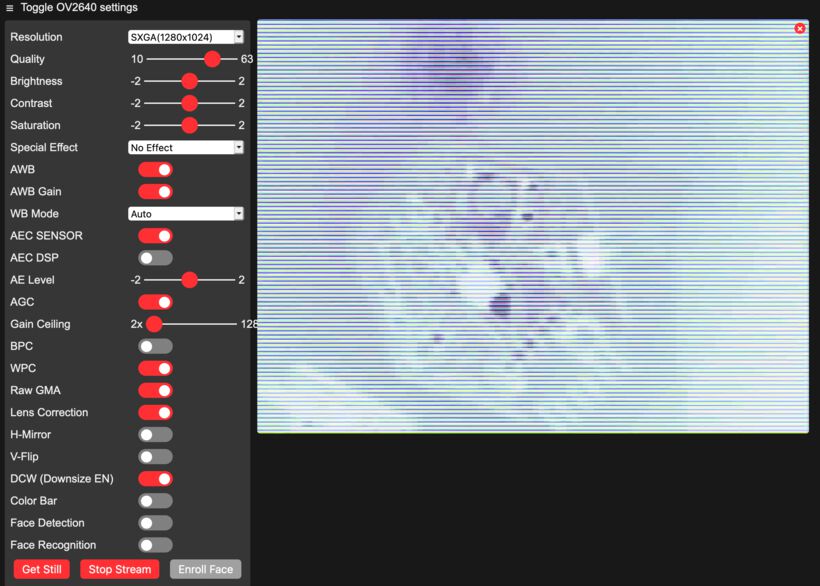
I tried adjusting all the sliders and buttons along the left, but nothing made the image any better. After a few minutes I figured that it was ok, I’d done enough for now, and closed the web server and disconnected the ESP32 from my FTDI.
Reflections
This was both a very fun and, at times, very frustrating week. Trying to figure out the errors in the code, while not yet having the knowledge to really know what to look for. But eventually I got to play with all of the input/output devices on my board.
What went wrong
I really wish that I had remembered that one final setting in the Arduino IDE to use megaTinyCore, so that my three fellow students hadn’t been stuck on a vague java error for 2-3 hours during the Thursday instructions class (╥_╥)
I also still feel that I have a mostly-IR phototransistor on my board that doesn’t work well with the LED lights in our house (which shine mostly in the blue spectrum). But that’s only minor, since it’s only purpose was to play with it using code.
What went well
Since I had already tested my board two weeks ago, I’d already gone through most of the troubles of getting my board and software set-up. So uploading my programs went quite well this week, and I could focus on learning more about the code side of things.
What I would do differently
I should’ve compared the spectral bandwidth of my old phototransistor with the new one so I would’ve seen that these were basically the same, so there would be no use in switching them.
Wrapping up
I’m glad that we’ve gotten to the point where we can program our boards (^▽^) However, this week was really simple, only playing with a blinking LED, button, and one input device (the phototransistor). I’m therefore a bit nervous about next week’s “Machine Week” in which we need to go from a blinking LED to a bloody moving machine that can perform much more complex tasks (●__●)
All Files Together
No separate files this week, because I all of my functions can be found throughout this week’s documentation.