With three fellow students, Douwe, Loes & Nicole, we took on an ambitious project to create a narcissistic lamp that wants to be seen and folds open and shines when it’s dark and it can be the only light in the room, while it’s sad and closes again when there’s enough other light because it can’t outshine the room anymore.
Assignments
Our tasks for this week are:
- Group assignment:
- Design a machine that includes mechanism + actuation + automation
- Build the mechanical parts and operate it manually
- Actuate and automate your machine
- Document the group project
- Individual assignment:
- Document your individual contribution
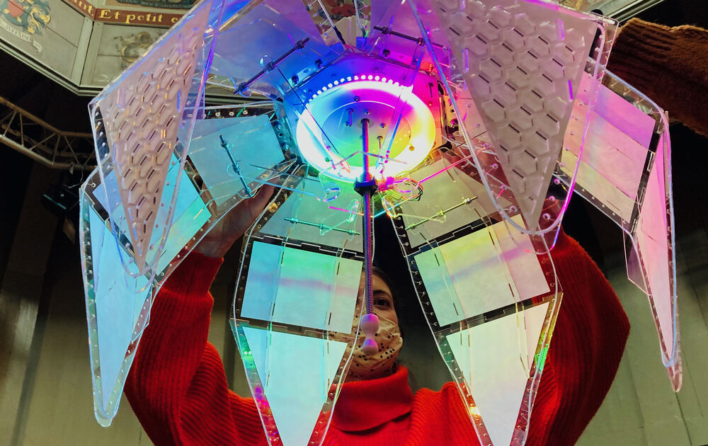
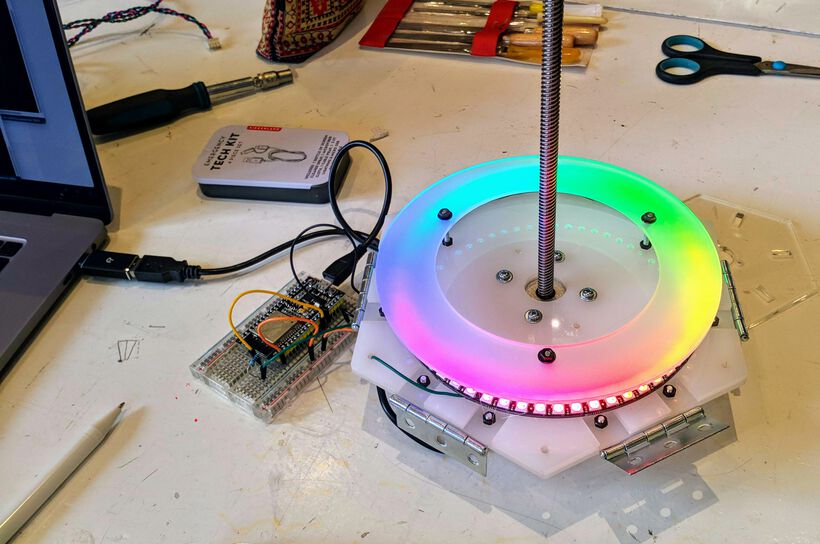
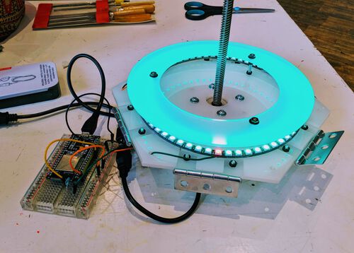
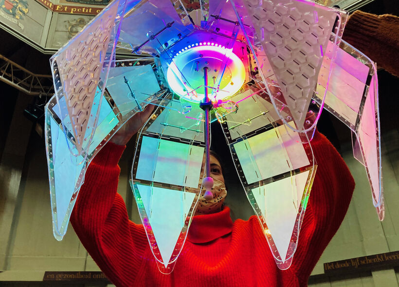
Hero Shots
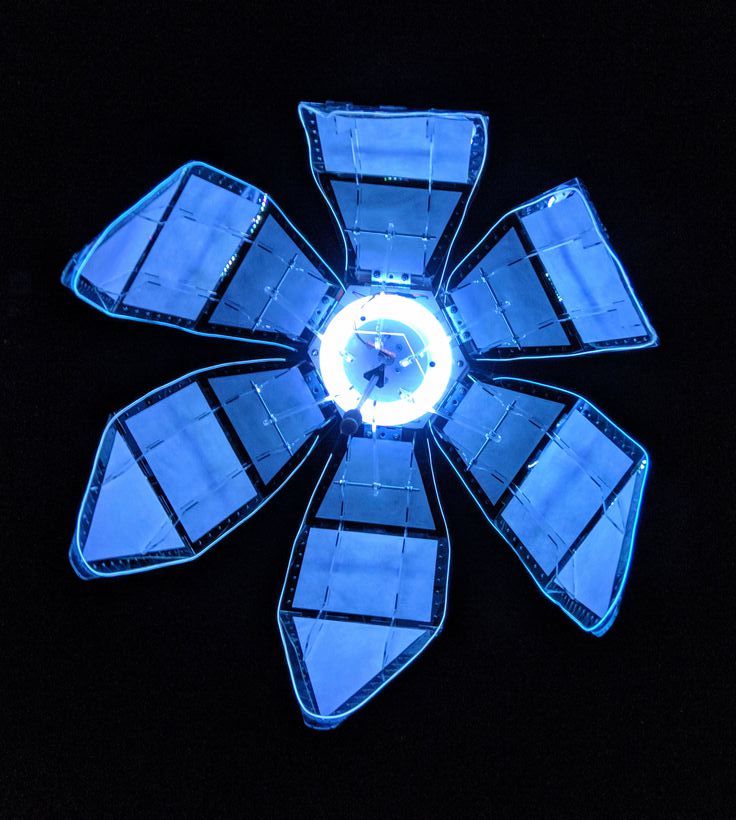
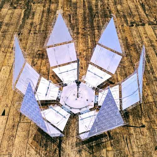
Showing some final results of our unfolding lamp for the tl;dr and hopefully showing you why the rest of this very long blog could be interesting to read (⌐■_■)
Stepper Motors
During our first morning of this week at the Waag, Henk gave us a short intro to the different types of stepper motors that we could work with. Such as the Nema 17 tha can do 1.8° degrees (or 200 steps in a full circle), and through PWM (Pulse Width Modulation), it can even do 32 micro steps within each step, making it possible to have 6400 steps within one full circle.

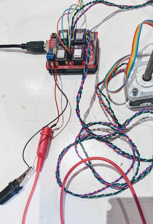
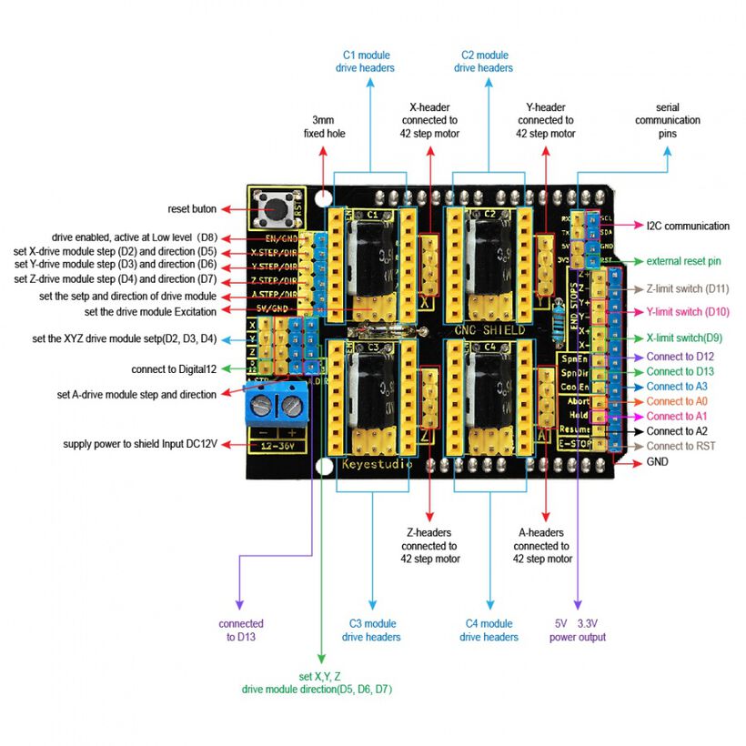
To make these work with a microcontroller, you need an H-bridge, which has the ability to flip the power flow (5V becomes GND and vice versa), so the stepper motor can turn both ways. Henk showed us a CNC Shield for the Arduino that has four connections for stepper motors. He took the power from an external source, using alligator clips and wires running to the two little blue connection points on the CNC shield.

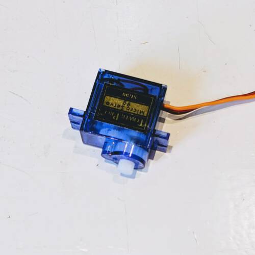
There were also a few servo motors on the table, but we didn’t get any more information about this (although I wrote down that the small blue one can move 9 grams?).

Inspiration
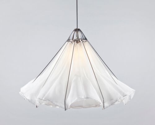
Our machine group started with a very broad brainstorm, throwing anything that inspired us into a dedicated “Machine Week” channel in Mattermost. From drawing robots that use magnetism and sand, to wall art that moves hundreds of tiny dials to form patterns, to kinetic smart facades that use voronoi patterns to open up, and the Hoberman structures. And then the amazing Shylight by Studio Drift was shared by Loes, which just WOW’ed all of us!
YouTube recommended another interesting video (based on the kinetic facades) that showed a process of a paper flower-like pattern folding and unfolding. It thankfully also showed the underlying system, which made the idea of an unfolding lamp seem like a doable machine to create.
And from that point onward, the idea of creating a lamp that would unfold was pretty stuck in our minds. I especially liked how Nicole put it, that were converging to creating an object that would still be a machine, but could also be art.
Fleshing Out the Concept
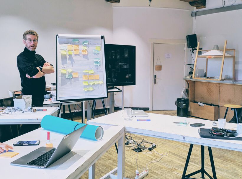
The first day we got together at the Waag, we started with a quick recap of our online brainstorm. To see how each of us four had interpreted the conversation and what we were planning to make. Nicole became the natural moderator for our group during these talks.
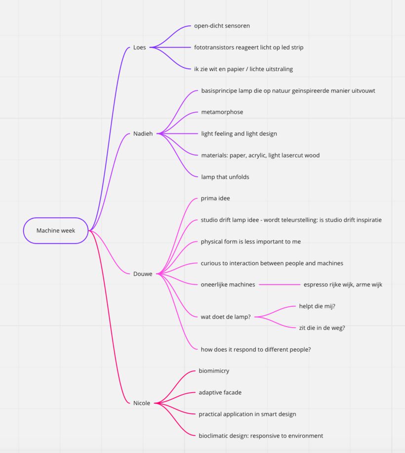
We then separated the main components of the machine; concept, functionality, interaction, design & materials.
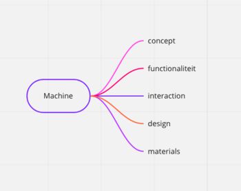
For a second brainstorm we took five minutes during which we wrote down what ideas we had in each of these five components on sticky notes that we posted on a big sheet.
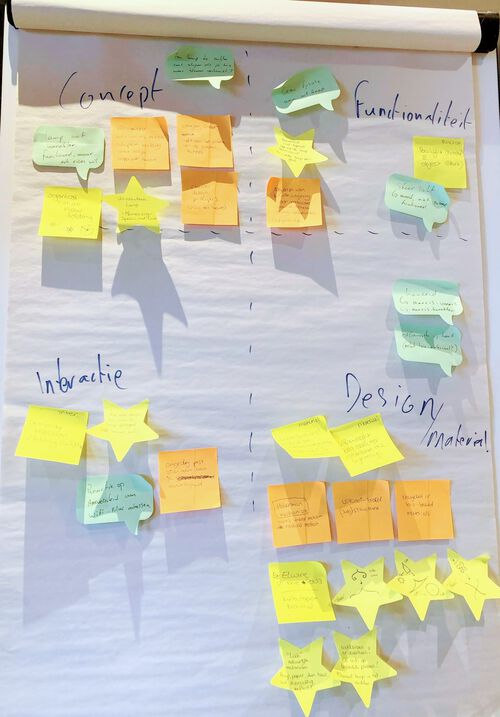
In terms of concept we were quite aligned to create a beautiful, organic, nature-inspired lamp that could unfold and have dimmable lights, made from transparent, light or white materials. Douwe had an interesting idea to give the lamp a character, to make it a narcissist that wanted people to look at it. Using sensors, it would shine brighter the more people were in the room. It wouldn’t really be a functional light, just one that wants to show off.
Functionality
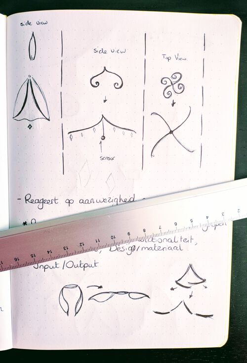
Next, Nicole created the set-up for the input and output that we’d want from the lamp, writing down the sensors along the input, such as a phototransistor, a microphone, a bluetooth/WiFi sniffer. And how it would respond to that; by changing the colors of the light between cold and warm, to have the lights become more or less bright, to fold open and closed.

After this point we felt that it was time to divide up the individual tasks. Thankfully, it seemed that we were all four interested in different components that together encompassed the whole lamp:
- Nicole wanted to focus on the mechanical side; how to operate the motor and to create the parts around the motor
- Douwe wanted to play with the sensors and give the lamp its character and respond to people
- Loes was interested in the lights, figuring out what lights to use and how these could be programmed
- I wanted to figure out the design of the lamp, to make it look beautiful
The Design of the Lamp
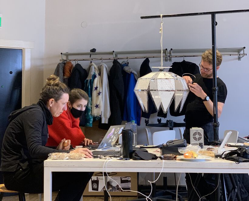
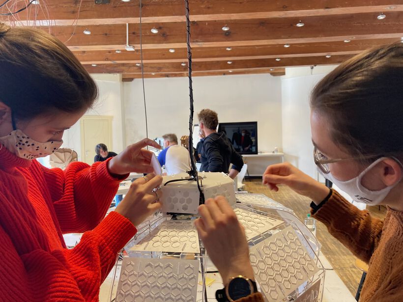
During the afternoon in the lab we all went our own ways, diving into our personal tasks, while occasionally checking in with the others to see how things were going.
Unfolding a Lamp
The first thing I wanted to figure out was how to unfold the lamp. I asked for advice on what types of natural unfolding processes people might know on twitter, and got back a whole array of input. Such as ferns unfolding, ladybug wings, coral, pull bugs rolling up, shy plants, pine cones, and of course, a flower unfolding.
I drew some possible unfolding patterns in my notebook, using the spiral unfold from ferns and the radial unfold from flowers as the main inspiration.
While searching for more practical examples of unfolding lamps/flowers, I came across a tutorial on how to make a Mechanical Flower open and close (which in itself looks amazing), but it also had a clear animated gif on how the concept worked:
This concept seemed very manageable, especially looking at the type of stepper motors that we could work with during this week. I shared this idea with the group, and everybody really loved the mechanical flower. I therefore worked with Nicole to follow this approach of petals opening up radially, using the well-known way many flowers in our world bloom. The spiral idea from ferns was also nice, but with only ±one week, we also had to face the facts that we shouldn’t do things too complicated.
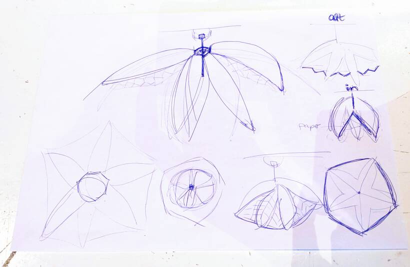
I brainstormed some more with Nicole on how the concept of the “opening flower” would look with the petals. Nicole started drawing sketches to see how it might look, and it helped us both to make sure that we were on the same line.
Petal Design
During Saturday morning breakfast I drew out a really rough design of how I imagined one petal to look. I knew that making these through 3D printing wasn’t an option, since they were much too big for that. I also didn’t want to mill them, because I needed/wanted to be able to experiment (often) and iterate. I would thus need to create something that could be made on a laser cutter.
Not that I minded that. With the laser cutter I could use transparent acrylic for the petals if everything went smoothly during the testing phase. However, it did mean that I couldn’t use any curved surfaces and would need to think in thin slices.
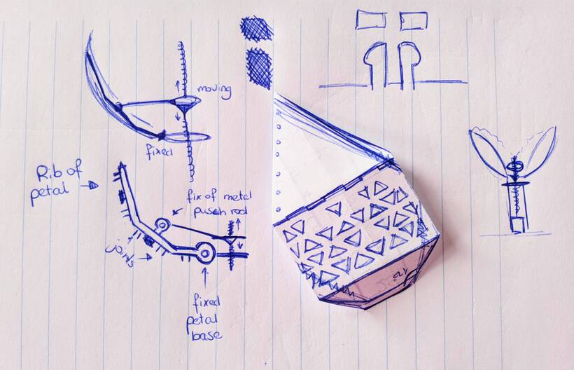
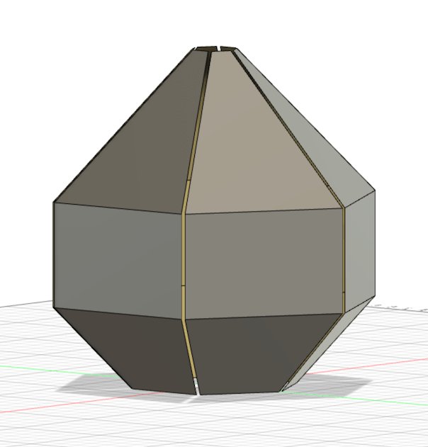
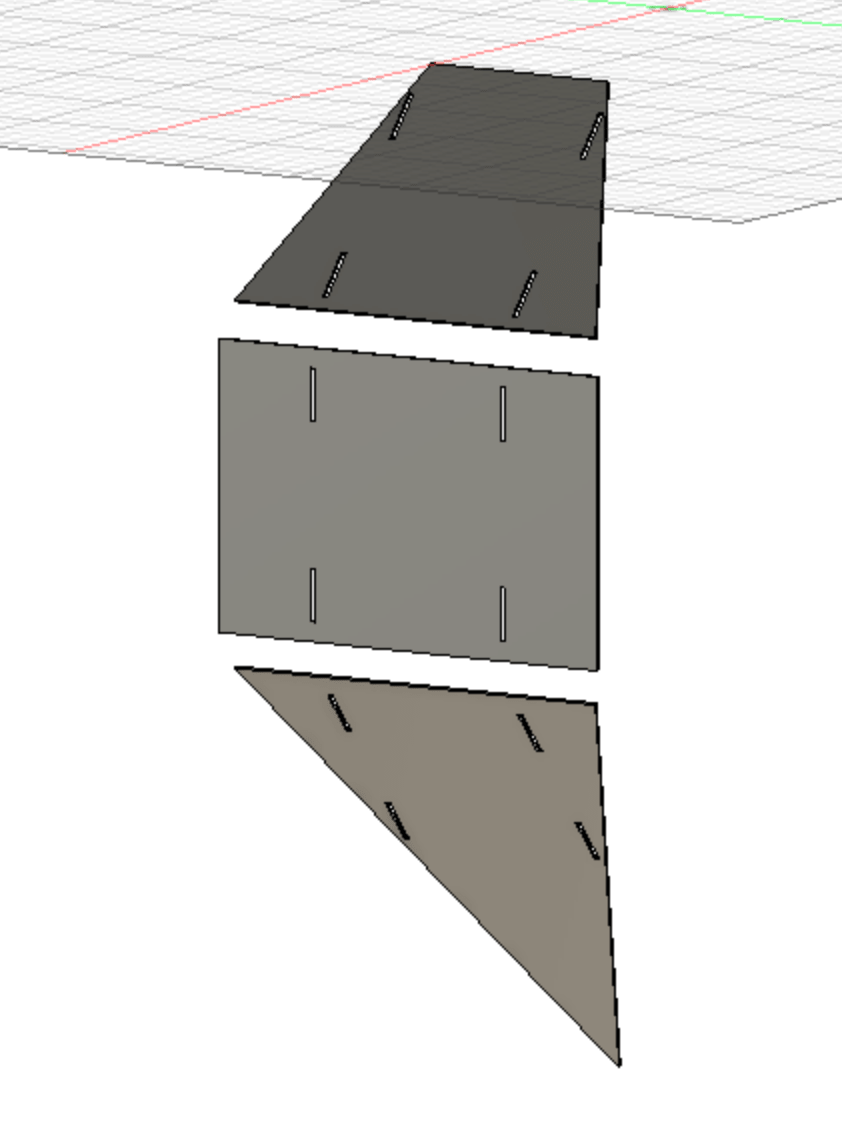
I wanted to have each petal consist of three flat surfaces that combined would give a low-poly idea of a petal. On the inside of these flat surfaces, to connect them, would be two “ribs”. These ribs would have joints on the outside to hold onto the flat surfaces. While on the inside they would have two rings: one to fix it to the base of the lamp and one that could be pushed against to open the petal.
I was torn at the start to make this in either Fusion 360 or with Cuttle. I knew that some parts would be much easier in Cuttle. However, because I was afraid I would make mistakes in the design if I had to create a 3D petal on a 2D plane, I eventually decided to go for Fusion.
The Base Shape
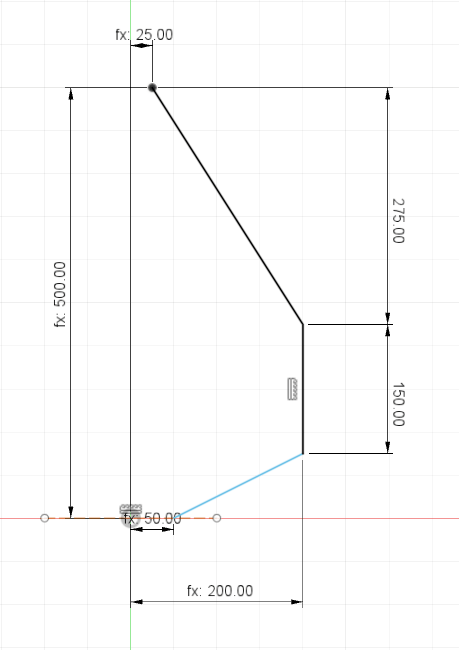
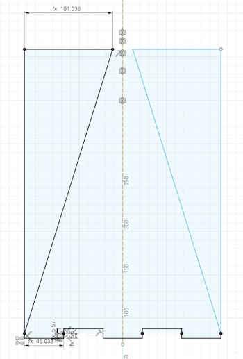
I started with the rough outline of the three surfaces that would make up the petal. Drawing three connected straight lines, guessing at the measurements for now. (PS: In almost all of the sketches and images below, the lamp is positioned upside down. Don’t ask my why I did it this way… ┐( ̄ヮ ̄)┌ )
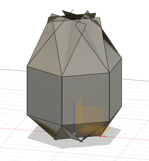
I then extruded these surfaces into three planes using a Surface Extrude and did a quick Circular Mirror Pattern to see how that would look when rotated around the center six times. That at least gave me enough of a start to see where this might go.
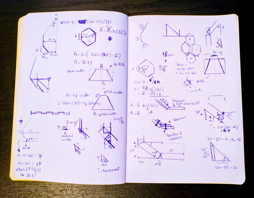
Throughout the design process I was creating User Parameters so I could more easily adjust the design later on. I had suggested to Nicole to go for a flower with six petals, since a hexagon is symmetric and the angles are easy to work with. I still used a lot of trigonometry throughout the entire design process to go from lengths to angles and back.
However, I quickly noticed that I really needed to discuss some of the finer details of how these petals would work together with the central motor. Thankfully Nicole was also online and we hopped into a Jitsi call during which we went over the concept of how the petals would open. I showed her my rough idea for the petal shape, and she showed the idea for “pushing” open the flower. We talked for about 1 - 1.5 hours and then we were both aligned in how to proceed with our separate parts.

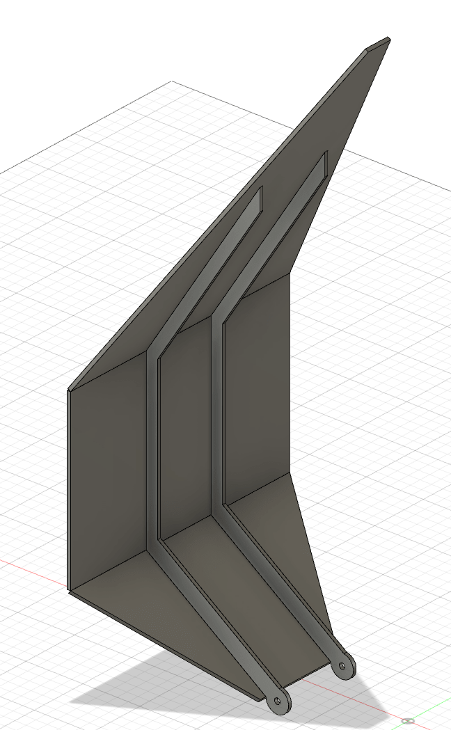
I continued to work on the petal design. To cut the bottom and top sheet in the correct shape, I created a sketch on top of each sheet, and then added triangles to the outer corners. Using some trigonometry I could calculate exactly how wide the triangle should be at its base to make it align perfectly when combined with five other petals.
Next, I fleshed out the internal rib a bit more, offsetting the base line that created the sheets, and adding a circle at the end that would connect to the base of the central stepper motor.

For a while though, I was unable to select the profile of the rib to extrude. After an online search I found a video with the answer. Apparently the Show Profile check mark was turned off for me (this can be found in the Sketch Palette that’s on the right when you are in Sketch mode). After turning it on, I could select the rib’s profile to extrude.
I added some joints to the outer side of the ribs, and to cut these out of the three plates I first used the Combine option, where I set the ribs as the Tool (but kept them), the three plates as the Target and set it to Cut. This cuts out any section of the Tool from the Target.

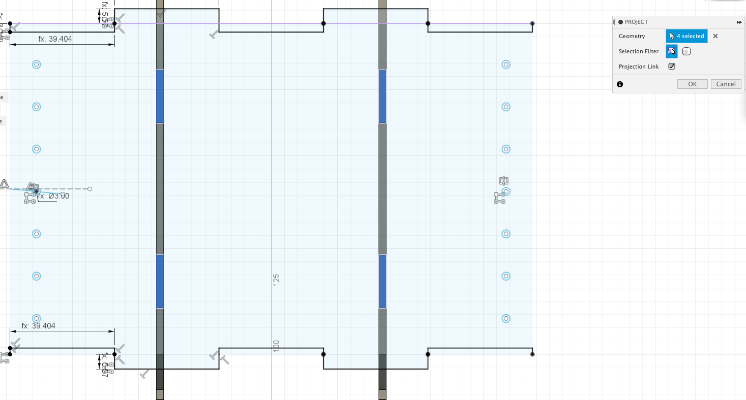
However, later on I actually removed this step and instead I Projected the joints into the sketches of the three plates and included them as holes in the extrusion, so I could see where those joints would be positioned.
Because I felt that those joints on the ribs could use a little extra support, I also added some finger joints along the edges of the three sheets that touched each other (this video was really helpful to get a start with the concept).
I set this up parametrically, so I had a fingers_num variable that I could adjust and then the number of fingers would update as well. Although I do then have to check the extrusion, because those often don’t turn out correctly after making more substantial changes to sketches (such as adding fingers).
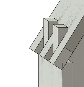
Because these joints weren’t 90°, it was a small (trigonometry) puzzle to figure out exactly how deep the fingers joints had to become to make sure that these plates wouldn’t touch (as you see happening in the image below)
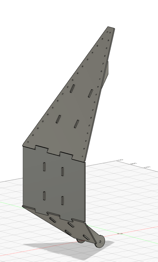
To be able to string the EL wire light string around each petal, I added a row of circles along the outer edge of two of the plates. And at that point a solid but bare-bones, first iteration of the petal was done.
Nicole had been working on the central plateau with the stepper motor in the meantime. She wanted to try and import my petal shape into her file and see if she could simulate the movement.
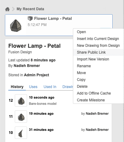
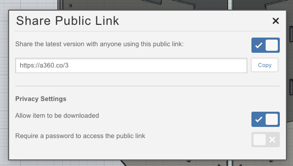
Thankfully it’s easy to share a full Fusion file. You click on the top-right most icon with the 3x3 grid of little squares. Next, find the file to share (probably in My Recent Data). Right-click it and select Share public link. This will open a new window with the link to share.
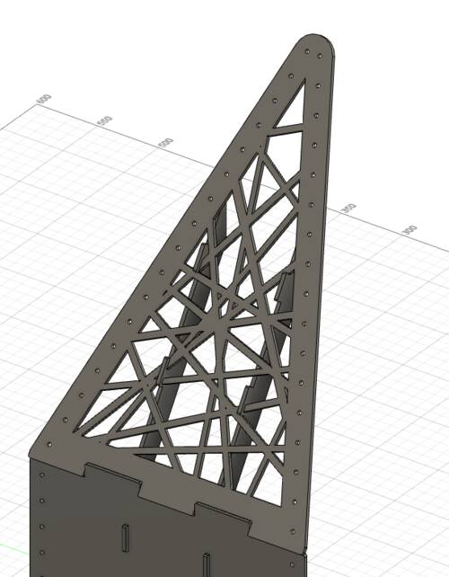
One final quick thing I wanted to try was to see if the petal shape would look just a bit more beautiful if a pattern was taken out from the central side.
It was late, so I didn’t want to have to look into creating exact patterns. I therefore added a bunch of randomly oriented lines, outlined each, and then carefully adjusted the extrusion of the plate to leave the gaps in the design (in all honesty, all this still took quite some time (*≧▽≦) but at least not that much brainpower). I felt that the petal looked instantly much better and less boring and robotic.

I did remove the lines from the sketch again, because somehow it felt odd to have such a large random collection of lines inside a sketch that was otherwise so nicely defined. Furthermore, I was expecting changes still to the size of the lamp, so this didn’t feel sustainable for those kinds of updates. Such as….
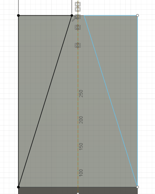
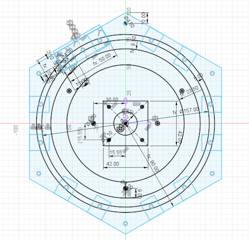
… At first I’d made the petal 50cm long, but eventually Nicole and I felt that might be too long, too heavy. I therefore updated it to be 40cm long instead.
I also played a little with the sizes of each of the three plates, making the bottom plate a little shorter, so the top plate would become longer. This also made the bottom plate’s angle less steep, making it able to rotate upwards further. By then I was really done for the day and went to sleep.
While back at it the next morning (Sunday morning) we all got together in a call to discuss our progress, and Nicole surprised us by having turned the petal into an awesome animation ♥‿♥ This really helped us to visualize how the lamp might look.
Refining the Shape
I continued working on the design of the lamp, making some minor adjustments after talking with Nicole again to see how it would align with her central motor parts, but also fine-tuning some other parts now that the major sizes were getting fixed.
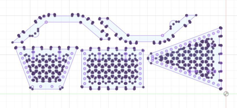
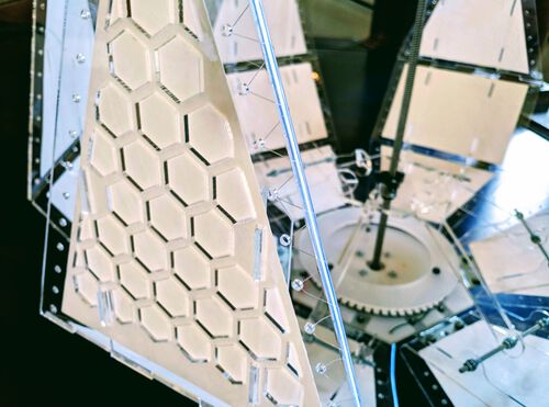
I figured, this being a lamp with six petals and a hexagonal base, creating a honeycomb grid on the inside of each plate would be fitting, and naturally I have a bias for all things hexagon. Thankfully there were several videos that showed how to create a hexagonal grid from one base hexagon by using the Rectangular Pattern (in Sketch mode).
It did actually take me quite some time to figure out the correct formula for the offset of the pattern in the 0° and 30° direction, based on the user parameters that I’d set for the size of the hexagon and the thickness of the sections between them (the videos just moved things by feeling).
2 * hexagon_pattern_radius * sqrt(3) + hexagon_pattern_thickness
hexagon_pattern_radius * 3 + hexagon_pattern_thickness * sqrt(3)
Doing it this way created a pattern that got much taller than wide. I therefore had to create a pretty big grid, before it was finally wide enough to cover the inside of each plate. Thankfully though there is a really handy feature where you can deselect any of the pattern pieces that you don’t want. Using only the pattern pieces that are needed keeps Fusion performing much faster I found.
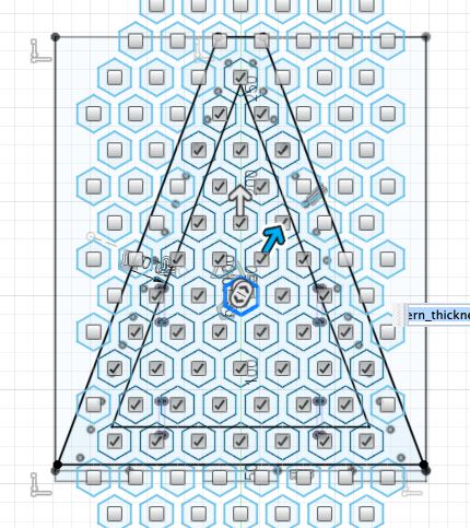
I created this hexagonal pattern in a new sketch, because I figured it would keep the sketch for the face with the holes and finger joints much cleaner. I made sure that the locations of the joints (with the ribs) did not have a hexagon taken out, as you can see in the image above right (I also projected the joints into the hexagon pattern sketches).
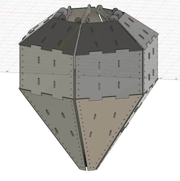
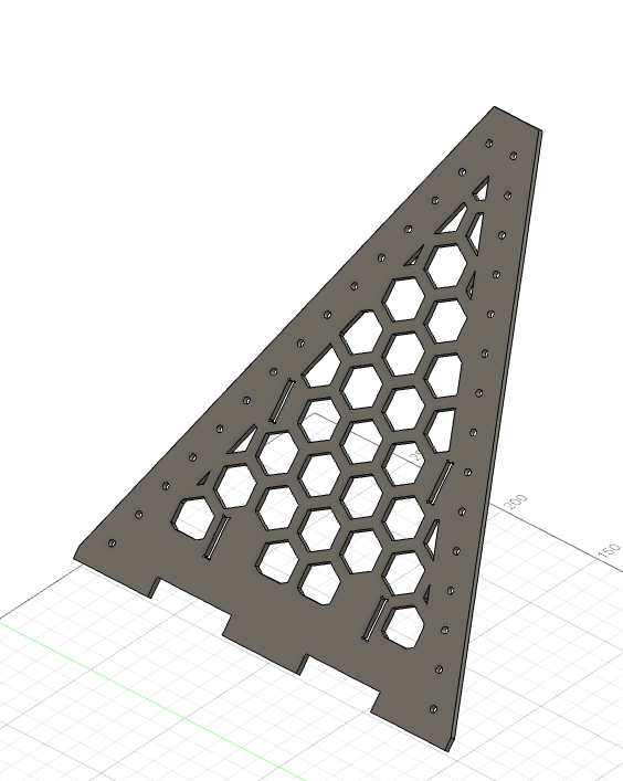
Thankfully, I found that making this hexagonal pattern into the petal instantly made it look a lot less boring.
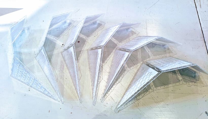
I shared the file with Nicole again, and she incorporated it with her design for the central mechanism and later shared the following image where the petals have been turned into transparent acrylic, which was the material we wanted to aim for.

No Easy Kerf in Fusion
Once I felt done with the design of the petal for now, I looked into how to export the design. Specifically assuming that there must be some easy way to include the kerf (the amount that the laser will cut away, and that makes the design no longer fit snugly together).
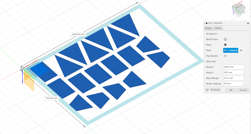
I started out following the same procedure as I’d learned during the Computer-Controlled Machining week: select all the bodies and go to Modify -> Arrange. Fill in the size of the “plate material”, which I happened to remember was about 70cm long by ±100cm wide for the cardboard sheets we used during the laser cutting week.

With the components having been arranged, create a new Sketch and go to Create -> Project -> Project Include and select all the faces to project into the sketch. Finally, right-click the sketch in the Browser along the left and choose Save as DXF.
I searched online for ways to include the kerf, but most things I found were very inefficient and required the user to create the kerf as a tiny offset within the sketch. That didn’t feel like a very failsafe way, you might forget it somewhere, or by changing something to your sketch at the start, could not extrude the shape correctly anymore (not including the kerf). Also, depending on how complex your design is, it could mean that you’d need to add a lot of offsets.
I found an add-in called DXF for Laser where you could export your sketch “for laser” during which you could give a kerf, which would then automatically be included in the exported sketch. That seemed like a step in the right direction. I did have trouble installing the add-on. It would go through the full installation process, but then it was nowhere to be found by Fusion, and not present in the add-in folder within the Fusion 360 folder in my Library.
Thankfully the add-in had a link to a “The installation failed” page. Here I followed the steps to download the Suspicious Package app (a name that makes you think twice on whether or not to install it, so I googled some reviews of the app first) to be able to open the .pgk file of the add-in, and then just manually copy the .bundle file into my Fusion 360 folder. This thankfully worked. Sadly I noticed that you could only select one face at a time for export. With only 5 pieces I could live with that. But then it also had an inconsistent error where sometimes it would close the Save as window immediately, before I could do anything.
Eventually I decided that I’d just have to go the “manually add tiny offsets to the final sketch” route, and then in Illustrator to manually remove the double line (because the original line would still be there as well) 눈_눈
The Creation of the Lamp
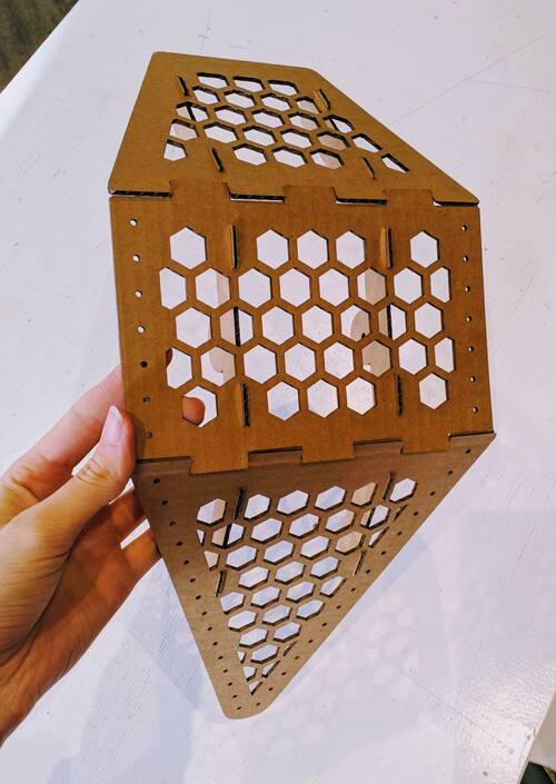
Although I really wanted to use transparent acrylic for the final piece, I started with cardboard for the first prototype.
A Cardboard Petal
I went to the lab early on the Monday morning to get a good start on laser cutting my design. I’d prepared a tiny “kerf” test in Cuttle, just to be sure that I’d set mine correctly.
While talking to Henk about the frustration of having spend almost two hours to find an efficient way to take the kerf into account with Fusion, he mentioned that there was an option to do this in LightBurn, the software to use the laser cutter. That would be very helpful indeed! A quick online search and deactivating the “Beginner” settings in the Preferences later, and I could set up a kerf when I clicked on a line to set its speed and power (•̀ᴗ•́)و
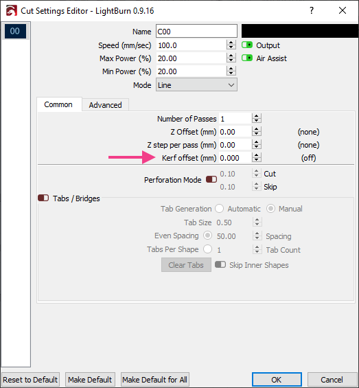
My tiny kerf test went perfect (I was using the same settings as I had for the laser cutting week, so I was expecting to have it right), after which I cut out my first petal. It took a bit of a push to get the joints on the ribs to go through the holes in the flat plates, but the whole model was sturdy as heck.
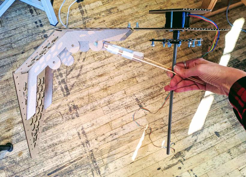
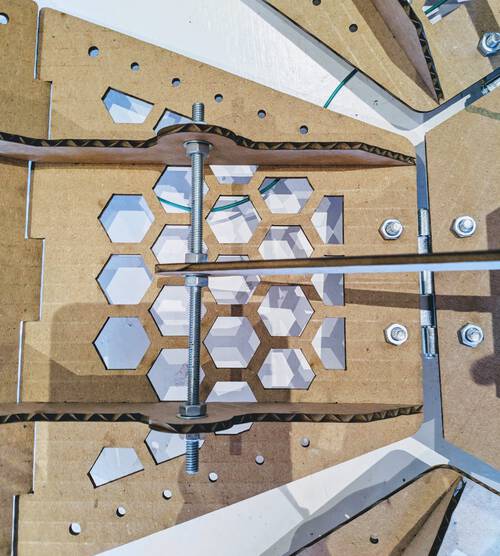
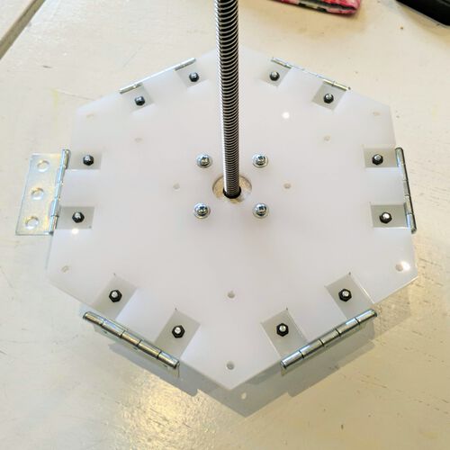
After Nicole got in the lab she had the central hexagons laser cut. She also found out that there is a “secret” space upstairs in the Waag filled with nuts and bolts from which whe grabbed a bunch so we could fasten the plates to the actual motor. Using painters tape we somewhat fixed the petal to the base and using wooden sticks we tried to mimic the movement of the middle plateau going up and down to open and close the petal.

This really was as “houtje touwtje” as it gets (^ᗨ^) . However, it shows us that there was potential. It also showed us that the placement of the connection point of the ribs to the inner hexagon plateau was much too low. The lamp would barely open when we moved our imaginary plateau up and down.
I quickly added two more circles into the Fusion design at places we thought could be about right and had these laser cut. I’d also gotten my hands on an actual hinge to connect the petal with the base plate. This being cardboard, Nicole just punched some holes into both sides with the wooden sticks to make the holes for the bolts (⌐■_■)
The point closest to the base plate turned out to be great, the petal could open and close the way we wanted within the space available on the inner thread.
Nicole felt that we had to change the concept of how the rib would be attached to the middle plateau moving up and down. We now had two “sticks” in a “V” shape towards the center. However, that created tension at the point of connection, since the sticks where not attached to the circles on the rib in the same plane, they were trying to bend the circles inward a little. For cardboard that wasn’t an issue, because it easily bends. However, for acrylic that would probably not work.
She investigated other possible options that could work while still relying on a laser cutter to create all the pieces. She found inspiration from one of the first videos that had appeared during our initial brainstorm about kinetic facades.
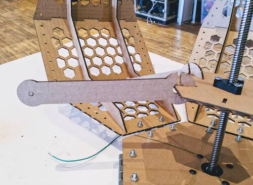
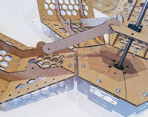
She explained the idea to me, to have slots inside the central hexagon plateau, and a connector with an opening to slide it into that slot. It seemed interesting, so we wanted to test it. However, Fusion wasn’t playing nice with Nicole, so I created a connector in Fusion and added the slots to the hexagon plateau, and had it laser cut.
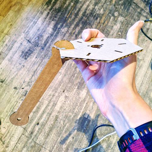
After fastening the new connector to the moving hexagon plateau and the petal, and rotating the central threaded metal rod by hand to make the plateau move up and down and the petal was opening and closing just the way we wanted (๑•̀ㅂ•́)ง✧
A Cardboard Lamp
The next day I was the only one of our group who could be at the Waag, with the other three spots taken up by the other team. Thankfully Douwe and Loes could work from home on their programming, and Nicole had a 3D printer to build some more pieces for the central mechanism, and work on the programming of the motor she took home as well.
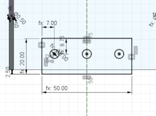
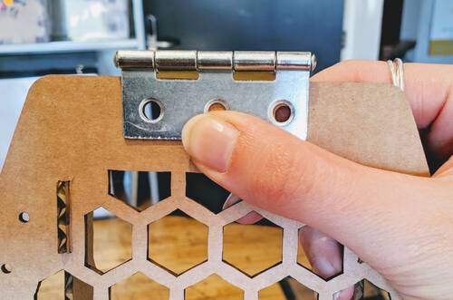
Nicole and I used a hinge on our prototype to connect the petal to the hexagon base plateau. However there were only two of them, and they were just a bit too small to provide the needed support. I’d therefore looked for slightly bigger hinges (that were somewhat affordable) from the hardware stores. I’d finally found some that were 50x40mm, with three holes (although we’d only need 2). With the pandemic I hadn’t been able to schedule a time to buy/pick them up. Nevertheless, I wanted to give it a shot and already have the two holes of the hinge added to my design. I could always update the exact measurements later if I got them wrong.
I new the total size of the hinge and kind of eyeballed it from the picture of the hinge online to set it up in Fusion.
I also removed the two circles along the rib that were no longer needed and did some other minor adjustments, and had a new petal laser cut.
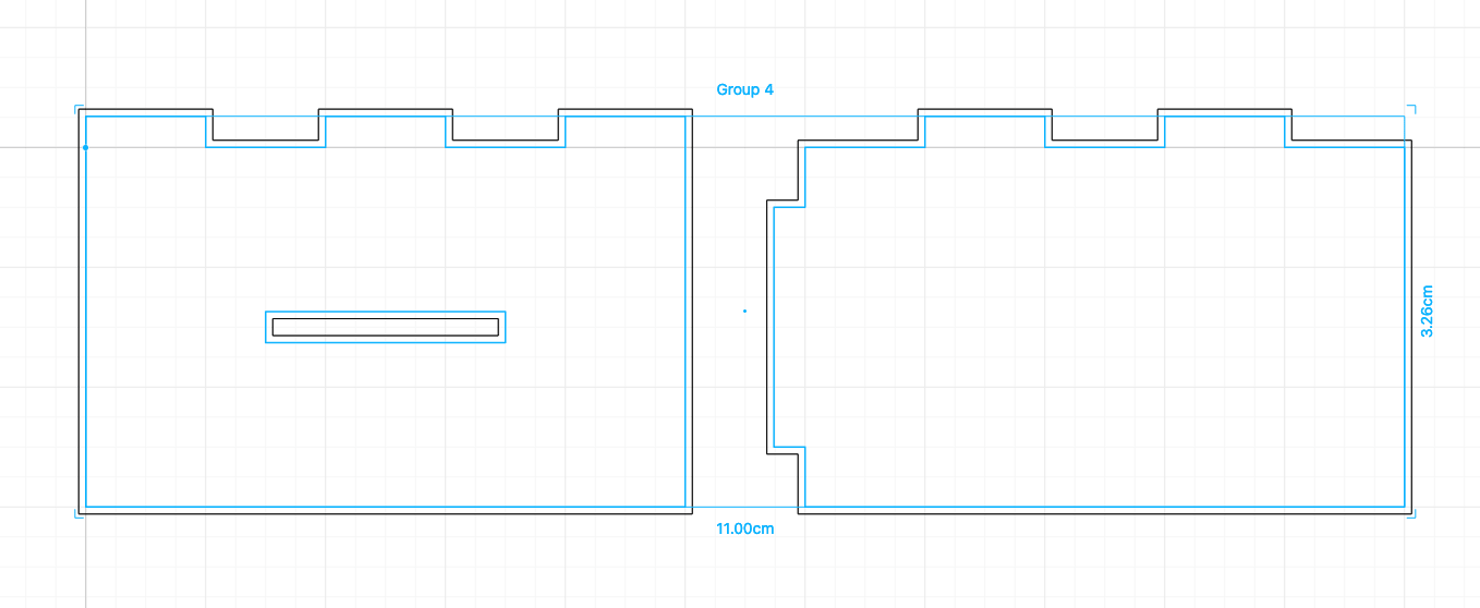
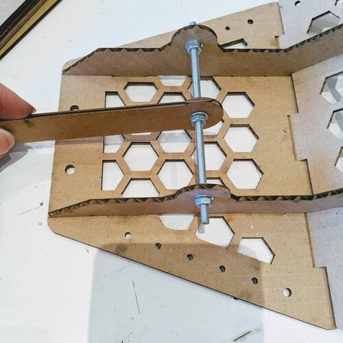
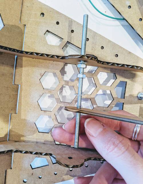
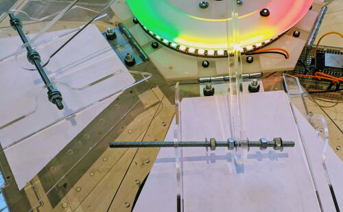
The day before I’d asked my partner if he perhaps had some thin threaded rod at his work. Thankfully, he works in a lab and was so kind to saw 6 pieces of 11cm (sharp edges taken off even) and also took a bunch of washers and nuts to (more) properly test the rotation mechanism with.
With my new petal (Nicole had taken the one from yesterday with her, since she couldn’t be back until next week), I attached the threaded rod to my petal and central connector:
That all seemed to be going well. I therefore decided it was time to create the other five petals. I did play with the exact length of the joints along the ribs, and the length of the fingers between the outer plates to see what might work best once this was made from acrylic and no longer (bendable) cardboard.
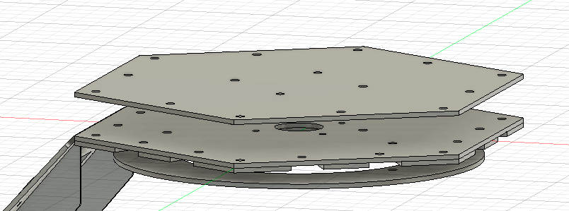
Nicole shared her Fusion file with me so I could also laser cut the central hexagonal bases and construct the lamp on another motor. Sadly, that file had somehow gotten weird, with things jumping around, and the history having become an endless array of tasks. I figured it would be better to recreate these plateaus in my own design instead.
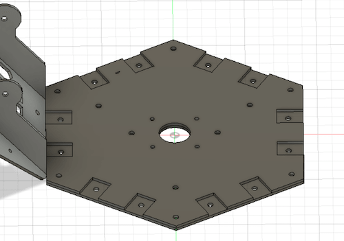
I could see some of the dimensions in the sketches of Nicole’s file, but just to be save I also measured everything myself with a caliper using the stepper motor itself. Due to some silly mistakes (forgetting holes for the hingers, forgetting to rotate the hexagon correctly, measuring everything 3-5 times to be sure), this actually took longer than I’d hoped. But by noon I had to hexagonal plateaus that fitted onto the motor!

Around this time, someone said that I should try visiting a local hardware store to get some hinges. I figured that would indeed be the best choice right now, since it would allow me to build up the full lamp today still and see how it functioned.
I called a local store, asked if they had hinges of about 40x50mm (which they did), borrowed a bike and visited the store, got some hinges and other stuff, and when I got back to the lab and checked how the holes of the hinge aligned with my petal, they fitted perfectly (๑•̀ㅂ•́)ง✧
I fixed all the hinges to the base plateau and quickly noticed that I couldn’t fit the movable hexagon plateau onto the metal rod, the distance to the top was too large. I also couldn’t first place the moveable plateau, and then attach the connector, because the opening of the connector wouldn’t be at the right angle.
I therefore figured out in exactly what steps a petal could be attached to the base plate and moveable plateau.
- First attach the connector to the moveable hexagon plateau, with the opening pointing upward.
- Fix the bottom of the petal to the base hexagon plateau using the hinge.
- Push the metal rod through the two openings along the petal, and move it along so it is halfway through one hole (and no longer through the other hole).
- Place in order: a washer, two nuts and another washer and move them along quite a bit.
- Once these are moved far enough that you can also fit the connector to the metal rod, slide it on.
- Next, add another washer, two nuts and a washer on the metal rod, and keep moving everything along.
- Slide the metal rod through the final hole (the other rib) and even everything out.
- Add a washer and nut on both ends of the metal rod, at the outsides of the two ribs.
- Even it all out again to be symmetric, and done!
That process actually took quite some time especially when having to do it six times (and then knowing that I’d have to take it all apart and do it again on the acrylic petals ʘ‿ʘ )
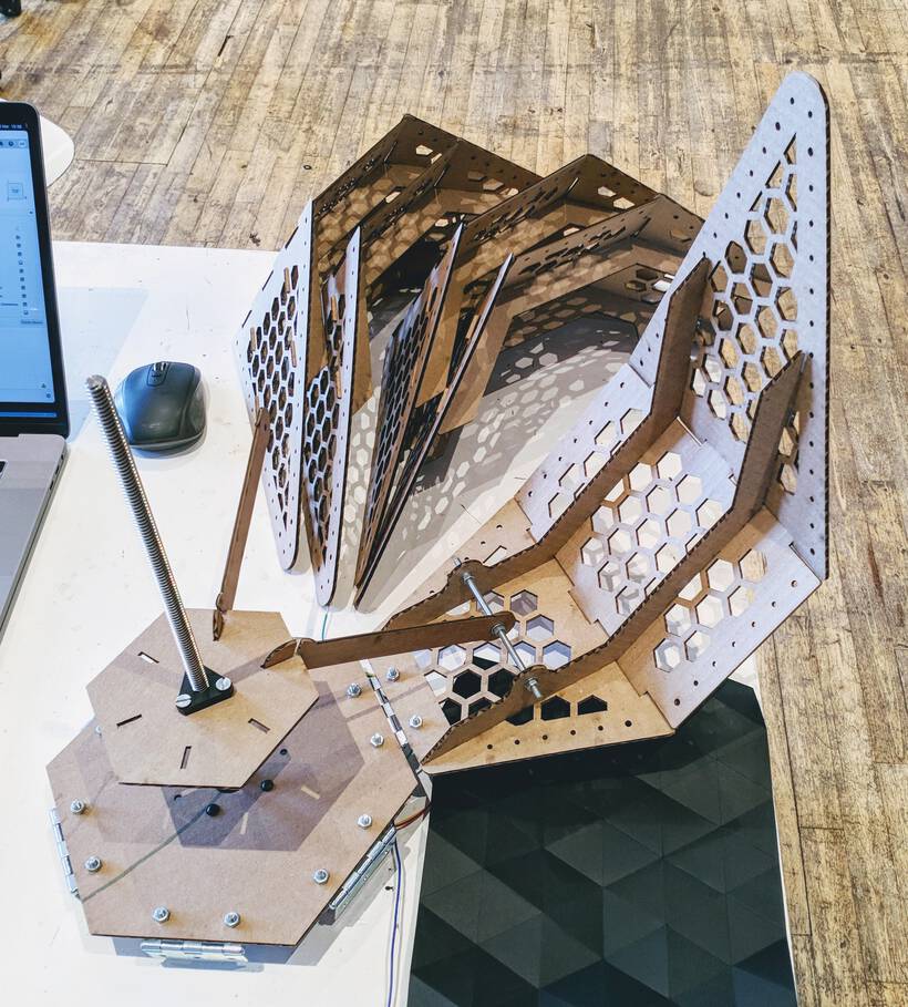
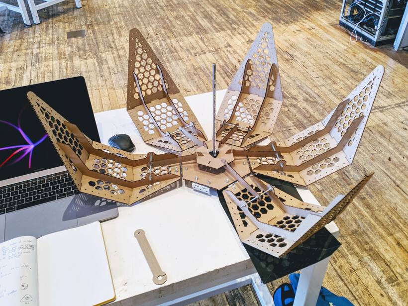
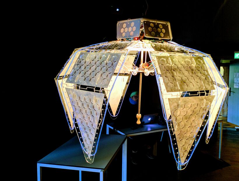
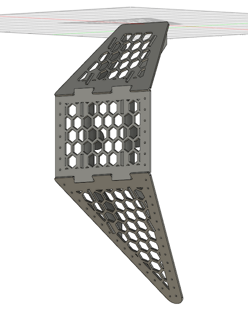
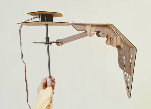
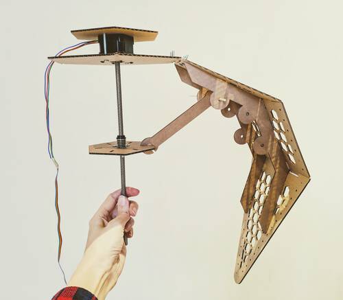
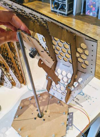
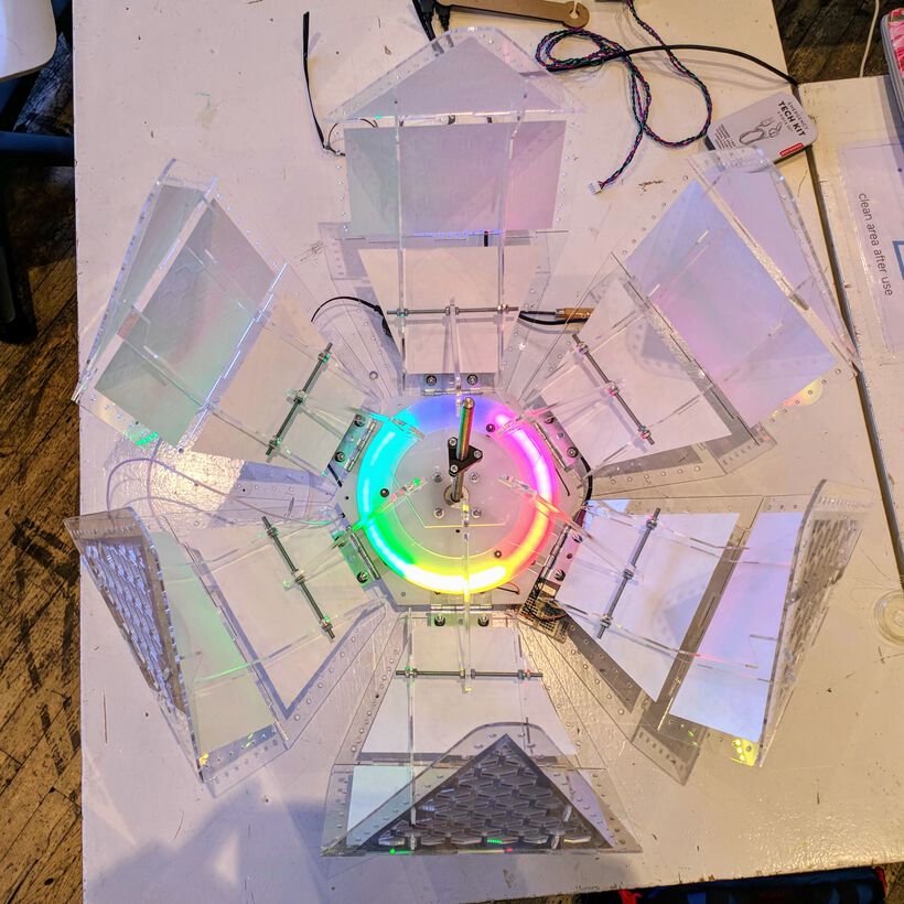
And when it was fully assembled, I have to admit, it looked damn cool!
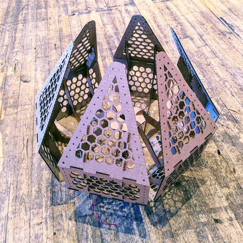
While holding the lamp in its intended orientation I could rotate the metal rod by hand to open and close the lamp:
Henk suggested to hook up the motor to his laptop to see if the lamp would open and close with the motor itself. After some fiddling with the wires, Henk had it all connected. He turned on the motor, and it the lamp opened, but it was making a lot of noise and it would often just stop after a little while; the motor was still working, but the petals weren’t moving.
Henk figured that the smallest stepper motor that I’d attached the lamp to wasn’t powerful enough. Damn! But thankfully it was possible to unscrew the base hexagonal plate from the motor without having to disassemble the entire lamp, with the help of some extra hands, and move it to a more powerful motor, pfew! (◍•﹏•)

With the more powerful motor, the opening and closing went without any issue, and the noise was almost gone too!
An Acrylic Petal
The next day at the lab it was time to recreate all the petals in transparent acrylic. I was definitely a little nervous, because acrylic is costly and I really wanted to minimize any errors.
While looking through the acrylic options I saw a really nice transparent sheet of ±3mm that had a blue shine to it. I asked the group if this sheet would be good to use. I measured the sheet’s thickness more exactly with a caliper around the corner where the plastic cover was already coming loose. It came in at around 2.8mm.
I then went into an hour of confusion as I was trying to figure out the best material thickness to use and the kerf of acrylic. At first I used the wrong thickness (using the cardboard still), then I remembered that I hadn’t focused the laser yet (I keep making this mistake!), and when I finally had those two things figured out I just couldn’t get the central slot to fit! Using the finger joints along the side I did know that a kerf of 0.1mm was perfect, but still the inner joint didn’t fit.
I increased the material thickness by 0.1mm and did another test. Didn’t fit. I increased the material thickness by 0.1mm and redid the test. Still didn’t fit… I did this about four times, all the while moving the laser further down along the material. And even at a material thickness of 3.2mm the central slot didn’t fit. What was going on?! ಠ_ಠ
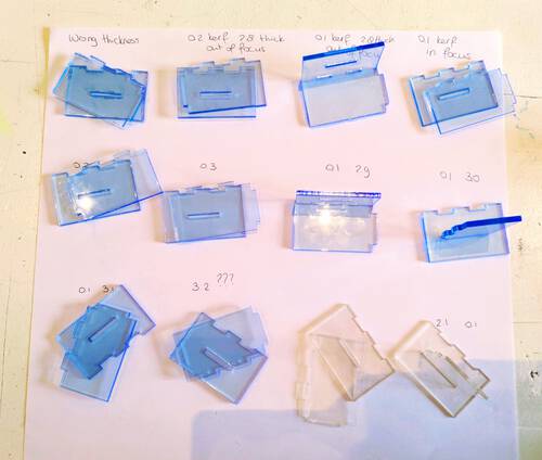
I grabbed the caliper, measured the thickness of the first kerf test pieces, which were 2.8mm. I then measured the thickness of the last kerf test pieces, which were 3.2mm. What? A 0.4mm difference? In less than 50cm difference in distance along the acrylic sheet?
I then measured the far corner of the sheet and got 4.2mm. This sheet thus changed thickness from 2.8mm to 4.2mm, that was not good, and not something I could work with to create press-fit petals (ᗒᗣᗕ)՞
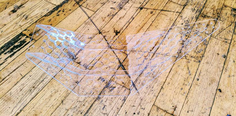
I therefore had to choose another transparent acrylic sheet to try again. This time it became a 2mm thick pure transparent sheet. Here I made sure to measure the thickness at all four corners, which came in at around 2.0 - 2.1mm. Two small tests later and I had a well fitting joint. Finally I could move on to creating a full petal.
I adjusted the material thickness of the Fusion 360 design to 2.1mm, and put in a kerf of 0.1mm in LightBurn. After the laser cutter was done, peeled off all the plastic covers and tried to push the rib into the slots of the bottom plate, I noticed that it sadly didn’t quite fit. I pushed a little too hard, and cracked the joint on the plate! (⑉⊙ȏ⊙)
I was so chaotic in my head at that time, after the whole issue with the blue acrylic plate messing with the kerf tests, and trying to work fast, because 3 other people wanted to use the machine as well. I didn’t take the time to truly look at the joints. Instead, I assumed the thickness of 2.1mm was just a little off, and increased it to 2.2mm.
This time the joints did fit, but it was actually a little too loose. I could put together the petal, but I shouldn’t really move the petal around too much or the plates would fall off.
But with one petal finally done, I figured I’d taken enough claim of the laser cutter for now, and that I’d do the remaining five petals once the other three people were completely done with their laser cutting jobs.
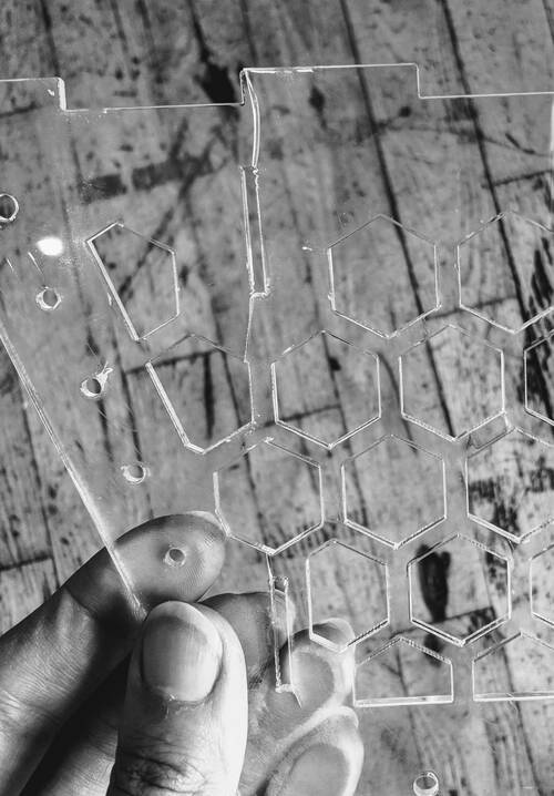
Back at my desk, and having calmed down a little, I finally took a good look at the joints of my petal, and noticed that these were all wiggly along the corners!
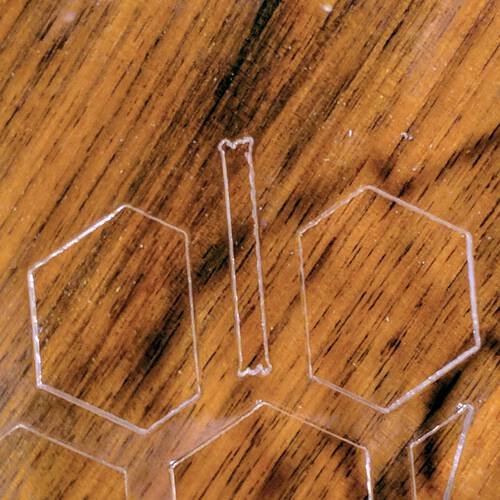
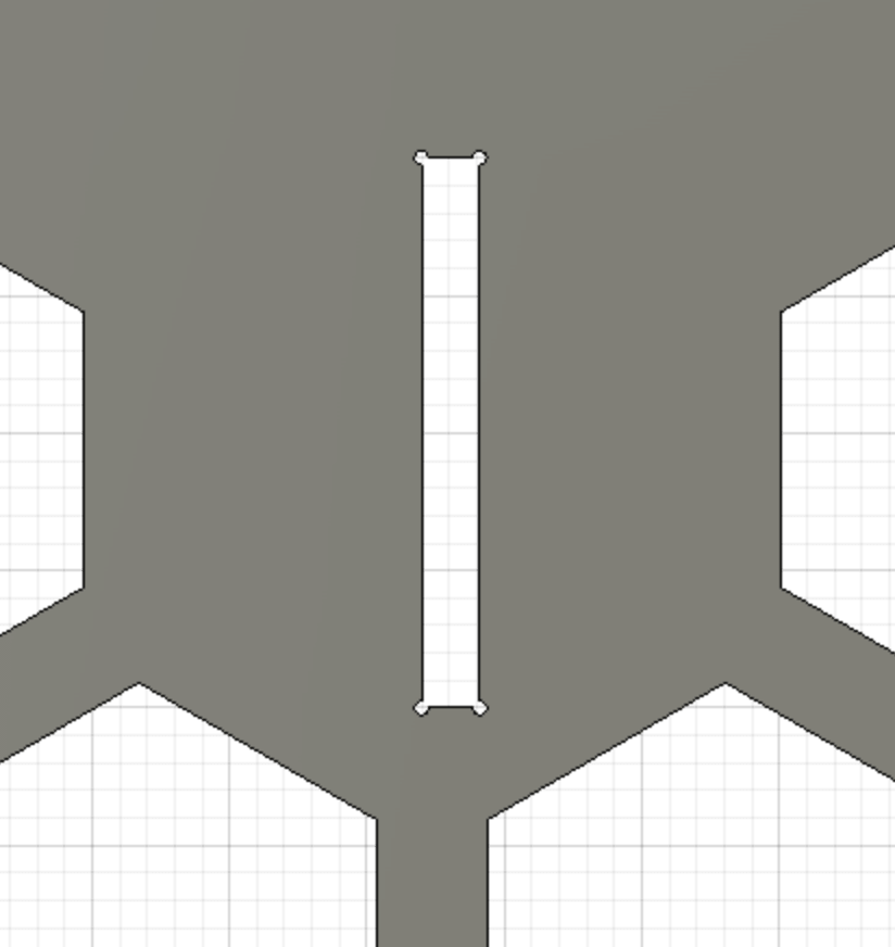
I think these came because I had created tiny circles along each corner of the joint. I had added these to my design after investigating how to make press-fit acrylic joints and reading that acrylic often cracks in the corners due to stress accumulating there. And that one way to reduce this risk was to add those tiny circles. I think the laser cutter created internal vibrations trying to draw these small circles which resulted in wiggles along the straight edges of the joints.
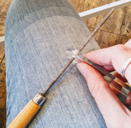
If I’d sand away the parts of the wiggles that were sticking inward, I should be able to make it press fit. Sadly, there are no small files that fitted into my slots at the Waag, so I couldn’t test it at the lab. However, I did have these at home.
I didn’t want to remove the tiny circles and decided to be ok with some filing work later on. I went back to a material thickness of 2.1mm, since this was correct, the wiggles had made the first acrylic plate break instead.
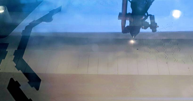
After the others were done with their laser cutting work, I went ahead and created my other petals. I did forget that the Waag’s laser cutter gets less powerful the farther it moves away from the top-left corner. Thus the power/speed settings I’d used to cut out the first two petals (moving from left to right along the sheet), weren’t enough to cut out some parts of the third petal sadly.
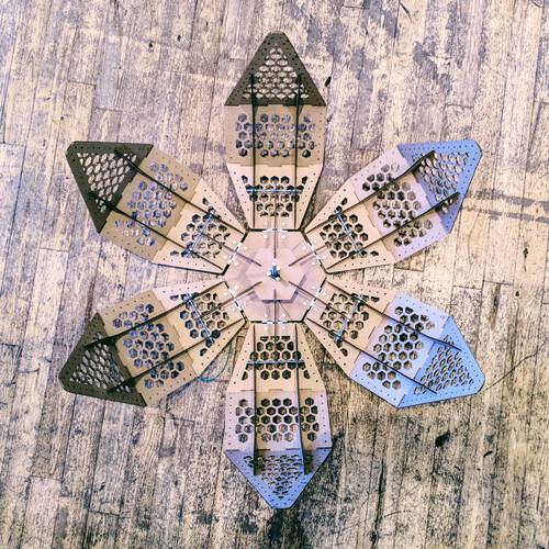
I rotated the sheet so I could start from the top-left of the laser bed again. I did have to grab a second sheet to cut out the final two petals, but I got all six acrylic petals cut.
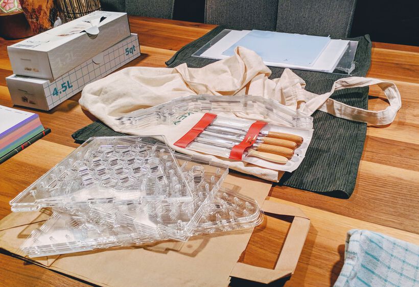
There was still a little bit of time left that day and I decided to also laser cut the paper sheet I’d gotten from the local paper store; the Tyvek 55gms (of 70x100cm) to cover the inner sections of the petals. This had a really nice texture through it that looked amazing when held in front of a light.
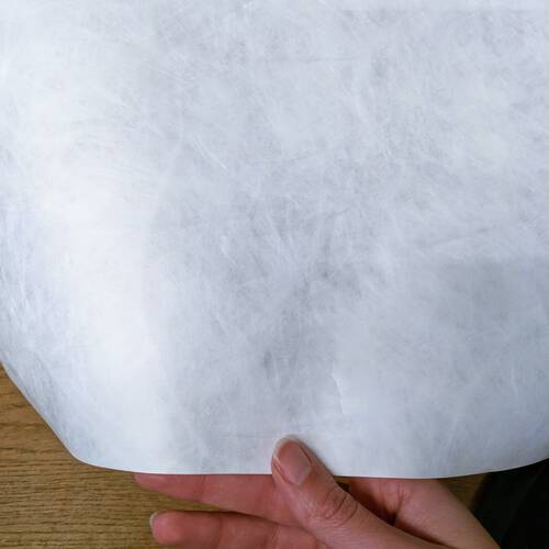
I’d already prepared the shapes in Fusion 360 during the afternoon. Covering the hexagonal grid, but not the full shape. I expected that it wouldn’t look nice if it covered the full area of the three plates exactly, possibly bunching up along the area with the finger joints, and covering the EL wire along the sides. (Furthermore, the paper sheet wasn’t big enough to hold 6 sets of the full outsides of the three plates).
It was already 19:00 by the time I was done with the laser cutting of these shapes. I knew that I just didn’t have the time to wait until the next morning to sand the joints and glue the paper to the acrylic plates. I therefore carefully packaged it all up and took it home.
After dinner I turned our table into a little “processing factory”. Picking two ribs and one of each plate, sanding the joint of one plate until they fitted those specific ribs, applying glue to a paper sheet, glueing it to the acrylic plate, placing it below a heavy book, and then moving on to sanding the next plate, glueing, placing under book, etc.
At around 22:00 I realized that I couldn’t finish this all in one night alone. I therefore managed to get my partner to help with the sanding. At around 23:30 we finally finished it all, except for one acrylic plate where I just wasn’t able to removed the plastic covering from one corner. I’d give that another shot in the morning.

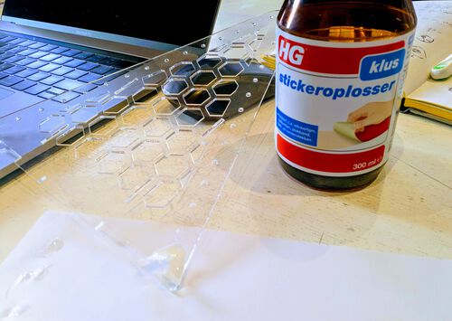
Back in the lab the next morning I asked Douwe to please help me remove the final corner of plastic from the final acrylic plate, because my arm was getting tired from the trying to rub it away. He was so smart to try the glue remover that we use to prepare a new copper sheet for the small milling machine and the plastic disappeared instantly! Wish I’d thought it that! (*^▽^*)ゞ
An Acrylic Lamp
With all the acrylic sheets prepared, I started assembling the six petals. Although 85% of all sheets clicked together really nicely in a press-fit way, I did use a little glue in some of the joints. The reasons being that I’d made one full petal at 2.2mm thickness, which was just too wide, and I’d probably sanded away just a little too much on another plate or two.
Due to some circumstances, I and Loes were the only two people in the lab this day, together with Henk of course. But it turned out to be a great day, where Loes and I cooperated really well throughout the day, combining the aspects of the lamp that we’d been working on separately; the physical lamp, and the lights to go inside.
With the petals assembled it was time to create the base and moveable hexagon plates from acrylic as well. And, as I remembered now, a ring to be positioned a little above (or below, depending on how you look at it) the LED ring that was placed on the base plate.
I hadn’t yet incorporated the led ring into my Fusion sketches, but with Loes and the actual LED ring there, I measured the inner and outer diameter and drew two rings in the sketch. I then noticed that the holes for the hinges were lying almost on top of the position of the LED ring! (⊙.⊙)
With the petals all done, I couldn’t change the dimensions of the hexagon plate, in order to make place for both. I asked Loes and Henk for help, and they said to create two plates where I’d take out sections around the nut+bolt of the hinges for the bottom plate, so they’d be “sunken” in, and the LED ring could pass over on top. Very smart idea!
Back in Fusion I made all the changes to the sketch of the base plate, which was getting a bit complicated by now.
I found a nice 4mm thick milky white acrylic sheet to laser cut these two hexagons from. Because this was twice as thick as the 2mm transparent acrylic I used for the petals I wasn’t quite sure what settings to use. I didn’t want to waste time and acrylic plate with more tests, so I looked at the test strip (of different materials) of ±4mm acrylic (which hangs to the right of the laser cutter) and figured that a speed of 25 and max power of 100% should be enough. I wasn’t sure about the min power though for the corners. I usually use 15% or 20%, but I set it to 30% to be sure. However, after having cut the hexagons, I noticed that the corners were brown, so 30% had been way too much sadly. Thankfully it was barely noticeable.
Loes helped by screwing on the hinges. I’d made the holes for 4mm bolts, but Henk didn’t have those types of bolts that were short enough. He did have a whole collection of 3mm (M3), and I learned that it was fine to use smaller bolts than the holes are meant for.
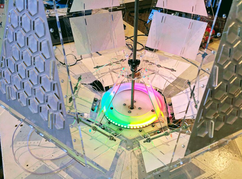
For the next step I really had to place and fix the LED ring in place. Thankfully Loes had more NeoPixel strips that she could continue with at home, while the LED ring stayed in the lab.
We placed the LED ring on the base plate and connected it to make sure that it was still working while we were going to fix it in place.
I’d just figured that we’d fix the ring with some double sided tape, but the bottom of the ring wasn’t nearly flat enough (or wanted to stick in the first place). I should’ve tested this first, so I could’ve made some tiny holes along the ring in the hexagonal plates to use string to fix the LED ring with.
Instead, Loes and I improvised and used some fishing wire that I’d brought along. Using the bolts of the hinges to string the wire along in a triangle across the LED ring. In the end the wire was strung so tightly that we could play music with it:
I’d also created a simple donut shape (with 3 holes for bolts) to be placed on top of the LED ring to diffuse the light more beautifully. This was from a thinner acrylic plate that was even more milky see-through than the base plate. We grabbed some really long 3mm bolts to position the ring a little above the LED ring. And once we plugged the LED ring back in again and saw the colors appear, it looked amazing!
I asked Loes how she was getting on with creating her own light programs, and she mentioned that she could use some help. She showed me the demo program that she’s been using for the NeoPixels, and I walked her through the base concepts of arrays and for loops that were used heavily in these functions.
As an example, I showed her how to create a function where we’d divide the 60 pixels in the ring into 6 strips of color, one for each petal.
Once that was working we noticed that naturally the 0th NeoPixel wasn’t perfectly aligned with a corner of the hexagon base plate, we totally hadn’t considered that.

We could undo the string and reposition the ring, but I figured that by now it was easier to do this through code and making use of a modulo function to cycle through the LED indices.
For this I first had to know what LED should become the zeroth led; what was the first LED that was in a corner. I wrote a quick ZeroLED function where I made all the pixels blue, except for the 0th one.
From this we saw that the sixth pixel was in the corner. I therefore wanted to basically have the pixel at index 5 become 0, the pixel at index 6 become 1, etc, the pixel at position 60 become 55. And then the pixel at index 0 should become 56, and this is where the modulus function came in, cycling through 60.
This was a little tricky to think about, so of course I didn’t do the math right at the start, but by using a Serial.println() of the values I figured out what was going wrong, and adjusted the math to work correctly. And then we had a colorful ring where the colors were nicely split at the corners of the hexagon (ノ◕ヮ◕)ノ*:・゚✧

After having gotten that working, I continued with the final elements of the lamp that still had to be cut from acrylic; the connectors and moveable hexagonal base plate.
With these parts experiencing the most pressure/force during the opening and closing of the lamp, I had these cut from 4mm transparent acrylic. First creating the hexagonal plate and one connector to test that they actually fit. At first it seemed that the connector was experiencing a lot of friction while moving along the plate. But after having removed the plastic cover (I had actually expected that it wouldn’t matter that much), it was very smooth. I cut out five more connectors, and started to assemble the rest of the lamp.
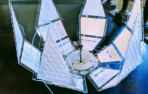
It was again a time consuming process to put together, but thankfully Loes helped as well. It was looking damn cool when it was finally assembled (⌐■_■)
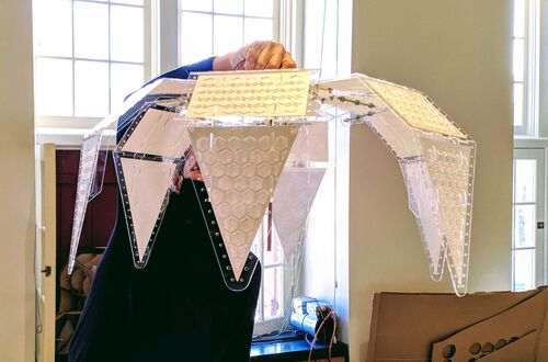

I did have to admit that this lamp was definitely looking more like a SciFi / alien satellite or flower than an organic one from Earth ✖‿✖ But oh well…
Loes had been playing on and off with the EL wire (a glowing thread) throughout the day. Henk had ordered some special part so she could connect the wire to a board and turn it on and off through code (that was the plan).
With the lamp now assembled we wanted to test the required length and look of “sewing” the wire along the outside of a petal. For this I’d brought some transparent nylon thread.
At first we kept the wire in between the outer edge of the petal and the holes, but we found that it looked even better if the wire was positioned right along the edge of the petal.
Due to it being late already, we only did a test along one side, but we were convinced that it was going to look great when fully assembled (the actual blue color of the wire that our eyes see can’t be captured on photos):
And that’s where the construction side of the lamp, the part that was my task, was (seemingly) completed for now. Nicole would make hood that would go on top of the base hexagon plate to hide the motor and boards, and would create something to be placed on top of the metal rod to place the paper behind.
I’d spend basically every, single, moment that I was awake during the past 8 days on this project (seriously, my boyfriend made most diners and did groceries and such), making sure that there was an actual lamp to open and close. I couldn’t work on it again until the final day, because I had interpreted the break week as a vacation and thus had promised my partner that we would go somewhere and unwind for a bit. But I was pumped by the end of this Thursday looking at our lamp, and how fun it had been working together with Loes throughout the day.

The Full Construction of the Lamp
The next day I was able to go to the lab was Tuesday, one day before presentation day. At this point most of the electronic parts were still separate. Only the NeoPixel ring was fixed to the lamp.
While I was waiting for the full group to get to the Waag, I looked through the NeoPixel code from Loes and the Bluetooth “sniffing” code from Douwe to understand how they worked and how to integrate them. Sadly, at 08:45 we got a message that Nicole was sick and that she wasn’t coming to the lab. However, she was supposed to create a hood for the top of the lamp in which the Arduino and ESP32 boards and wires would be hidden, and from which we could hang the lamp.
It was really time to hang up the lamp. I therefore brainstormed really quickly with Loes to create another hexagon plateau with a few more holes to function as the top plateau, from which we could hang the lamp. I created the design in Fusion, chose a 6mm thick white acrylic plate, and had it laser cut.
Getting the Motor to Work
I asked Douwe to figure out how to actually hang the lamp, since I really had to focus on the programming side. Because a second point of mild panic was that Nicole wasn’t able to send us her code that she’d worked on for the motor over the past week, because she wasn’t able to handle any more screentime. I therefore hand to figure out how to operate a stepper motor asap (◍•﹏•) Thankfully Henk send me some example code to use with the CNC Shield on top of the Arduino:
#define EN        8 //Negative Enable pin
#define X_DIR     6 //Direction pin
#define X_STP     2 //Step pin

int delayTime = 50; //Delay between each pause (uS)
int stps = 6400;// Steps to move microsteps 1/32 (200*32 = 6400)
void step(boolean dir, byte dirPin, byte stepperPin, int steps) {
  digitalWrite(dirPin, dir);
  for (int i = 0; i < steps; i++) {
    digitalWrite(stepperPin, HIGH);
    delayMicroseconds(delayTime);
    digitalWrite(stepperPin, LOW);
    delayMicroseconds(delayTime);
  }//for i
}//void step

void setup(){
  pinMode(X_DIR, OUTPUT); //direction pin = output
  pinMode(X_STP, OUTPUT); //step pin = output

  pinMode(EN, OUTPUT); //negative enable pin  =output
  digitalWrite(EN, LOW); //start negative enable pin at low
}//void setup

void loop(){
  step(true, X_DIR, X_STP, 6400); //true equals back towards motor
}//void loop
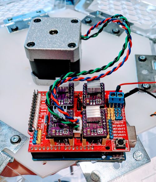
I grabbed an Arduino with CNC Shield from the lab, and using one of my photos of Henk’s explanation of stepper motors, I could figure out in which way to connect our stepper motor (the X direction).
A quick online search showed me that the true/false from the first argument of the step() function determines the direction of the motor.
I knew that the lamp couldn’t be fully opened and closed while it wasn’t hanging (too much pressure on the inner connectors). I therefore programmed a short “bounce” back and forth. Kind of like the standard blink program, but with the stepper motor turning instead of an LED turning on and off:
To get this to work I had connected the CNC Shield to an adjustable power supply (through the wires going into the blue “screw connector” on the CNC Shield), because it needs 12V. At first the lamp wouldn’t move and I wasn’t sure why. To debug, I connected a multimeter to the end points of the adjustable power supply, and saw that it read 8V (I thought, but it was actually milli volts, I wasn’t noticing the little m at the bottom of the screen), no matter what voltage I set on the power supply.
I asked Henk and he showed that there was am Off/On button (with the blue rim around it) that actually turns the power supply on (I had been using the circular power button in the lower left), oops (*^▽^*)ゞ
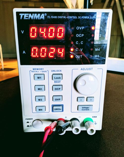
With the “bounce” code working, I asked Douwe to hold the lamp in the right position for a bit, so I could test if the lamp would be able to open and close fully with this motor (or if we’d need an even more powerful motor). I only made the crappy video below, but the lamp was able to open and close fully! For this I simply used the Off/On button on the power supply: I fully closed the lamp by hand, uploaded the motor program to always be opening, turn on the power supply, let the lamp open, and turn off the power supply when I felt it had opened all the way (and vice versa for closing).
Connecting the Arduino & ESP32
While Douwe was looking into hanging the lamp, arranging a stand to hang it from, adding a hook to the top, and creating metal rods to fix the new top plate to the base hexagonal plate, I looked into how to make the ESP32 talk to the Arduino. While looking for tutorials online, it seemed that connecting the TX and RX pins on the two boards and using Serial should do the trick.
However, some tutorials seemed to indicate that you needed a level shifter to connect the TX of the Arduino to the RX of the ESP32 dev board, because the ESP32 runs on 3.3V and the arduino outputs 5V on its pins. However, some other tutorials didn’t do this at all, and said it was enough to just connect the Arduino’s 3v3 pin to the ESP32’s 3v3 to power the ESP32 through the Arduino.
At some point even Henk wasn’t sure what the right way was anymore. I though that (hopefully) because I only wanted the ESP32 to send to the Arduino (the number of bluetooth devices found), but not to receive anything back, that it could work without the level shifter? While Loes looked into getting us a level shifter-like device (which Douwe later picked up at a nearby hardware store), I tried to connect the two boards and send data from the ESP32 to the Arduino.
Thankfully, on the Arduino’s CNC shield there are still two pins marked as TX and RX (in the top right of the image below). I found a “pinout” of the CNC shield on this page, which I used quite often throughout the day to figure out what other pins I could use to connect the NeoPixels and EL wire for example.
I followed the code section from this video tutorial, but also other tutorials, and wrote a simple program that I uploaded to the ESP32:
void setup() {
  Serial.begin(115200);
}//voide setup

void loop() {
  Serial.print("ESP sending");
  delay(1000);
}//void loop
On my Arduino I uploaded a similarly simple program:
char readString;

void setup() {
  Serial.begin(115200);
}//void setup

void loop() {
  if (Serial.available() > 0) {
   readString = Serial.read();
   Serial.println(readString);
  }
}//void loop
I connected a GND of the ESP32 to a GND of the Arduino, the TX1 pin of the ESP32 to the RX pin of the Arduino, and the RX1 pin of the ESP32 to the TX of the Arduino (although I now think this wasn’t needed, since only the ESP32 was sending). I finally connected the 3v3 pin of the Arduino to the 3v3 pin of the ESP32.
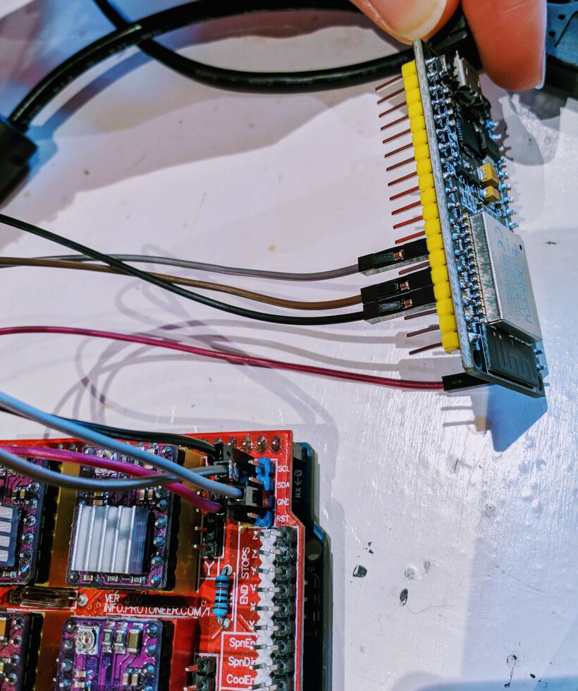
And when I opened the Serial Monitor from the Arduino connection, I saw that the message that the ESP32 was continuously sending out was being received by the Arduino! It was coming in letter by letter, but that was fine, since I was only expecting to send one number at a time.

With that seemingly working, I reworked Douwe’s Bluetooth sniffing code to only send the number of Bluetooth devices found to the Arduino. I uploaded the code below and tested it by checking the ESP32 Serial Monitor, and it was indeed only returning an integer (and new line I guess).
// This part includes the necessary Bluetooth libraries
#include <BLEDevice.h>
#include <BLEScan.h>

// BLE devices scan
int scanTime = 1; //In seconds
BLEScan* pBLEScan;
int BLEnumberDevices;

void setup() {
  Serial.begin(115200);

  BLEDevice::init("");
  pBLEScan = BLEDevice::getScan(); //create new scan
  //active scan uses more power, but get results faster
  pBLEScan->setActiveScan(true);
  pBLEScan->setInterval(100); // the interval
  pBLEScan->setWindow(99);  // less or equal setInterval value
}//void setup

void loop() {
  BLEnumberDevices = GetBLEDevices();
  Serial.println(BLEnumberDevices); //Send to the Arduino
  delay(1000); // wait for a second
}//void loop

//Scan the number of BLE devices
int GetBLEDevices() {
  BLEScanResults foundDevices = pBLEScan->start(scanTime, false);
  int BLEnumberDevices = foundDevices.getCount();
  // delete results from BLEScan buffer to release memory
  pBLEScan->clearResults();
  return BLEnumberDevices;
}//int GetBLEDevices
I added the same bit of code to the Arduino motor program to check the Serial that I’d used for the test and print the results returned from the ESP32.
Trying to upload my code to the Arduino I got uploading errors because the Arduino IDE could no longer locate the Arduino. I had already connected the Arduino Uno to the ESP32 with the TX and RX pins, and apparently the Arduino was defaulting to those, and no longer to the USB connection. When I unplugged the TX and RX wires, the uploading worked again.
However, something didn’t work. And even after struggling for an hour or two, I just wasn’t able to figure out why. For one, I could no longer open the Serial Monitor to see what was being send to the Arduino. While the TX and RX pins were connected, the Arduino IDE wasn’t able to find my USB connection to the Arduino. I still can’t explain how I managed to get it to work for the simple test before ¯\(°_o)/¯ . I looked back at my photos to see how I’d connected things, but it was the same as I was trying now, except that more wires were connected to other parts, such as the motor and the NeoPixels.
Not being able to look at my Serial Monitor while the ESP32 was connected to the Arduino shouldn’t be a reason for the actual transmitting of the data not to work. I’d created a simple program to activate the motor when the number of Bluetooth devices received from the ESP32 was above or below a certain number, but no part of that conditional was ever activated. The hard part now was that I had no idea what the Arduino was actually getting from the ESP32, because I couldn’t check it.
I knew that the ESP32 was sending an int, but even if I made the readString on the Arduino be an int as well, it never made the motor move. I tried to look for answers online, and found this extensive explanation of “Serial Inputs”. Here I saw that I could use a byte instead of an int, since I knew that the number of Bluetooth devices wouldn’t be higher than 255, and the information said that Serial was able to send a byte. I therefore made BLEnumberDevices and readString a byte, uploaded to both boards yet again (while disconnecting the wiring in between the two boards), but still, the motor remained silent.
I tried using SoftwareSerial to make two other ports on the Arduino into a TX and RX, but I still couldn’t open the Serial Monitor on my Arduino after I reconnected the ESP32 to these to new TX and RX ports.
At ±16:00 I had to make the tough decision that I just had to let the ESP32 go sadly. At this point I still didn’t really have a lamp that functioned well, only separate bits and pieces, and I really needed to first have a working lamp that opened and closed based on something. I felt very bad for Douwe, since that meant taking out his contribution to this project, the Bluetooth sniffing code, but after 2-3 hours of struggle I just couldn’t make it work with the knowledge I had at this time (If I ever find myself wanting to connect the Arduino and ESP32, perhaps I could try some thing from this page, which I found later while writing my documentation).
Bringing Everything Together
With the Bluetooth part missing, I needed some other way to make the lamp move based on some sensor. During the brainstorm we’d already discussed a light sensitive sensor, to make the lamp open and close based on the amount of light. Since I’d played with a phototransistor during the “Embedded Programming” week, this seemed the safest way to proceed, with only an hour remaining on Tuesday.
I got an LDR (light dependent resistor) that is typically used on breadboards from Henk and looped it through a hole at the top. Loes and I looked up how to connect an LDR to an Arduino, and saw that it’s sort of a like a “T-junction” to an analog port with the LDR on one side going to 5V, and 10K resistor going to GND. Loes quickly grabbed some wires and shrink sleeves and soldered such a T-junction with a resistor in between.
Using the “CNC Shield pinout” I figured out where the A0 pin was diverted to and connected the LDR. I wrote a really simple program that did and analogRead of that pin and then write out the value with Serial. This seemed to work fine, and I let it be, since there was one final thing to fix before the day at the lab ended; getting an end-stop inside the lamp.
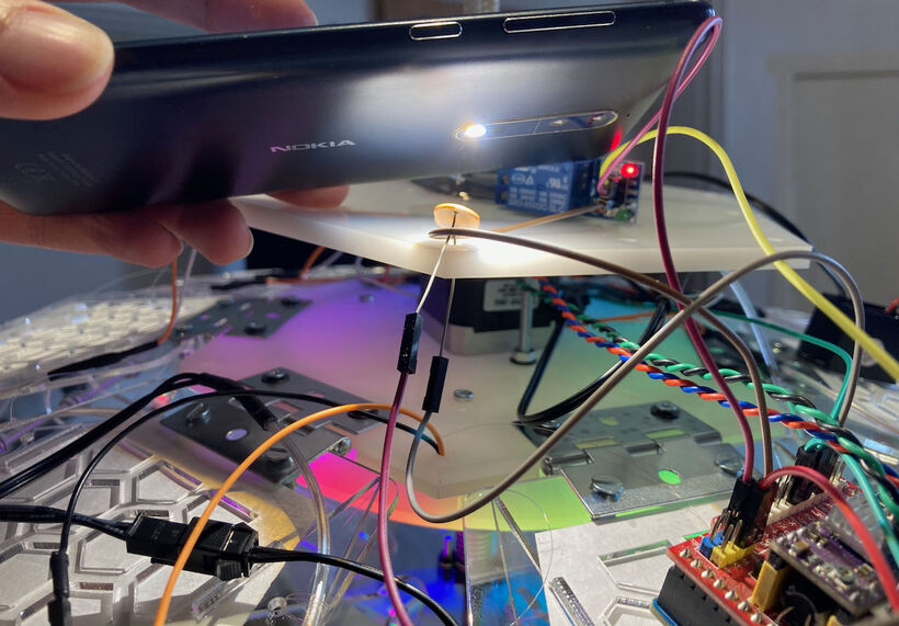
Some time after noon Henk had given us an end-stop to work with, since our lamp could possibly break itself if it opened too far. Furthermore, I could use this in my programming to calibrate an “absolute zero” every time the lamp was powered on, no matter how far it had opened or closed at the point that it was shut down.
Loes had been working on a way to attach the end-stop inside our lamp, using a long metal rod and glueing the end-stop to the end of the rod. We wanted the end stop to be activated when the small moveable hexagonal plate in the center would move up.
With the end stop fixed inside the lamp, and its 5V, GND and data line connected to the Arduino (we had run out of GND and 5V points at that time, and Loes had created some “Y-junction” cables to go from two to one), I again wrote a really simple program to do a digitalRead on the end-stop pin (D2), and then write it out with Serial. When we pressed the little arm on the end stop to make contact, it switched from printing 1 values to 0 values, so we had a working end stop! (๑•̀ㅂ•́)ง✧

I quickly tried to write a program that would use the end stop and the motor, but somehow the motor would stop opening the lamp before it ever reached the end stop. At that time I didn’t understand why yet. Something I had to figure out soon.
Now that I knew that all the separate parts were functioning; the NeoPixels, the motor, the EL wire, the LDR and the end stop, I still had to program it all into one. However, the day was at an end, so I figured I’d try to abstractly “recreate” the lamp’s sensors and outputs at home using a breadboard and continue programming there.
Loes and I did notice how the top side of the lamp was one GIANT mess of cables, and we asked Douwe and Nicole to look into this and come up with a (simple) solution on/before the next morning.
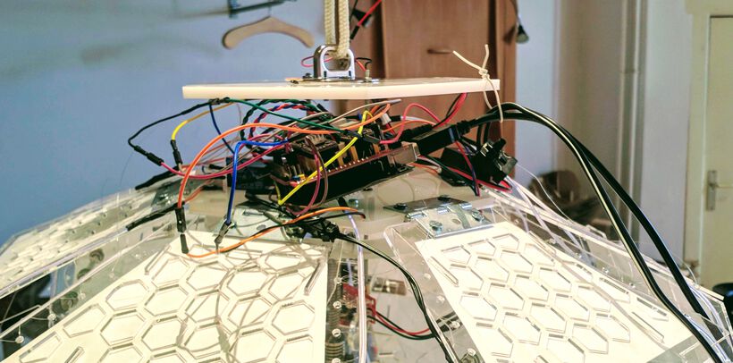
And so, this is how Loes and I left the lamp at the end of Tuesday. Still a lamp that wasn’t truly functioning, and that was, well, quite a cable mess. And we were less than 1 day away from having to present it (⑉⊙ȏ⊙)
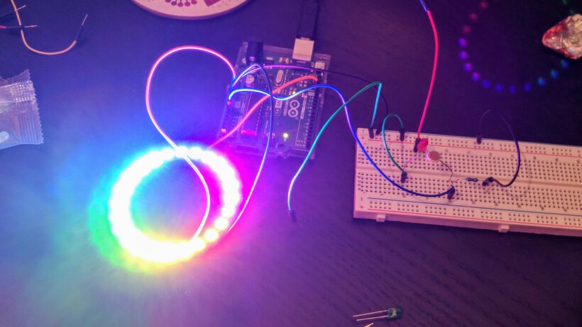
That evening I sadly didn’t have all that much time to program, because I was in an interview for an hour (for a book that I wrote that recently came out). I did set up a tiny NeoPixel ring that I could bring home from Loes, and another LDR set-up in my breadboard. I then used loads of Serial statements in my code to understand what the theoretical motor was doing at any time.
I managed to figure out why the lamp’s motor had (seemingly) stopped before it had reached the end stop. I had programmed the NeoPixels to turn on after the lamp had opened far enough and twinkle. However, one loop of “twinkling” took quite a while, and the motor could only move 800 steps farther upward once the NeoPixels had done one round of twinkling. The motor thus hadn’t stopped, but the microcontroller was still working on the NeoPixels for most of the time. I therefore removed any twinkling action of the NeoPixels until the lamp had fully opened and the motor wasn’t needed anymore. In general this page on the Adafruit NeoPixel library helped me to rework parts of Loes’s NeoPixel code into the final versions.
I decided to create five lamp “states”:
- Calibrate | The lamp is powered off. When it’s powered on it will first move open until it reaches the end stop. During this opening I show the rainbow pattern on the NeoPixels.
- Full Open | Once it reaches the end stop, it’s in “Full Open” mode. During this mode it will twinkle yellow-orange-red-pink lights, using one of Loes' functions.
- Closing | If it’s too bright, the lamp will want to close (because it can’t be the only shining light). The motor will start to move the hexagonal plateau down, thereby pulling the lamp’s petals closed. At first the NeoPixels will be light blue-purple-ish (another function from Loes), and at the end it will become deep blue and fade out.
- Closed | The lamp is in “Full Closed” mode and everything is off (although for the final lamp the EL wire remains on).
- Opening | If the room is dark enough the lamp will open, moving the hexagonal plateau upwards. At first only the EL wire is on, after a while the NeoPixel ring will fade in (from yellow), until it reaches the end stop.
By the end of the evening I had some dummy version working (I didn’t have an actual end stop, so I used a “number of steps” approach, e.g. if(total_steps > closed_state_steps) ...). In the video below you can see it first in the Opening state, then reach the Full Open state. I then come in with my flashlight and not point it at the LDR for a while (filming with one hand and operating a flashlight was difficult it seemed), but eventually I shine on the LDR, and the lamp goes into Closing state, and eventually reaches the Closed state.
Back in the lab early, together with Loes, I really wanted to test my dummy program on the real lamp. I naturally had some kinks to iron out, but after about an hour I had a lamp that could cycle through its states on its own! (ノ◕ヮ◕)ノ*:・゚✧
There was still one problem. It would only function properly when we had attached both a 12V adapter and I had the USB from the Arduino plugged into my computer. When I took the USB out, the lamp’s motor would stop once the NeoPixels turned on. Perhaps the power wasn’t enough once the lights turned on?
Henk gave us a 5V 1.5A adapter to attach the NeoPixels to. However, the NeoPixel ring went crazy! The lights were all over the place, flickering and changing colors (⊙_☉) Perhaps the 1.5A was too low?
EDIT | I realized during the Output Week a few weeks later that I’d forgotten / didn’t know that I had to connect the GND of both power supplies together as well, otherwise you’d get the flashing pixels.
I’d brought a 5V 8A adapter, and we tried with that, but the flickering remained. We were really out of time to try and figure out why this was happening, so Loes and I decided to just use the USB connection from the Arduino to a 5V adapter (which did work) and the 12V adapter to power the lamp. Sadly, we hadn’t taken the USB cable into account to go through the top hexagon plate, and thus had to loop that thick cable around the outside.
While I kept tuning the code (the EL wires weren’t always going on when I wanted), Loes replaced the rope by which the lamp was hanging by a nice looking metal wire, Douwe was working on the video, and Nicole had created some plates with the laser cutter to hang from the top hexagonal plate behind which the wiring would be hidden.
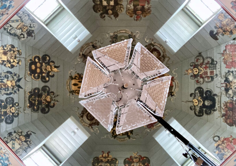
Presentation Time
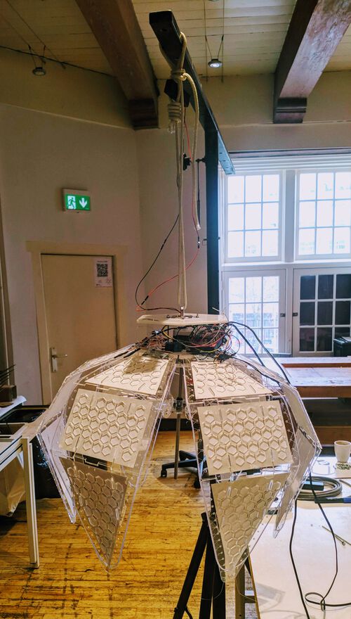
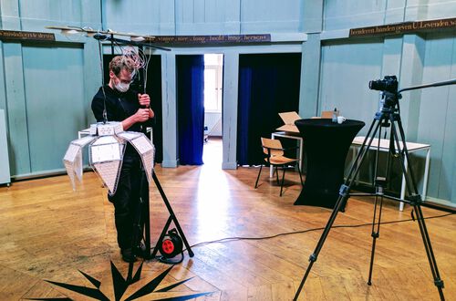
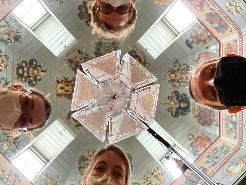
At around 11:00 the lamp was “finished” enough to transport it upstairs and into the amazing Theatrum Anatomicum, which has such lovely old paintings on the walls and ceilings. Douwe had made a set-up in the center of the room to take videos of the lamp in action.

Although the lamp was working as I wanted most of the time, at some points it would suddenly start “twitching”. This could happen at any opening state (not only when it was fully opened), and it could happen with any light routine, although the twitching was often paired with the rainbow light state.
Having run out of time to figure out why this was happening, I found out that I just had to power off the full lamp and turn the power back on again to make the lamp “reset”.
As the window blinds slowly moved down, the lamp went from “Closed” state into “Opening” and finally “Fully Opened” state, just as it was supposed to. Seeing it behave like that, knowing the stress the coding had been, doing it all in barely a day, felt really amazing!
We actually added another pole with lights hanging from it next to our lamp, which we could turn off and on and make the lamp open and close again, without having to wait on the window blinds (the lamps themselves are just out of view on the image below).

Seeing the lamp open and close in the dark, Loes and I realized that it actually looked best when the EL wire was always on. I therefore made one more adjustment to my code to keep the EL wire on from the start (all that trouble that Loes went through to be able to turn on and off the EL wire! ಥ_ಥ )
Personally, I liked the rainbow state the most, because I just like vibrant colors (⌐■_■) . That was really the main reason why I added the rainbow lights to the Calibration phase.
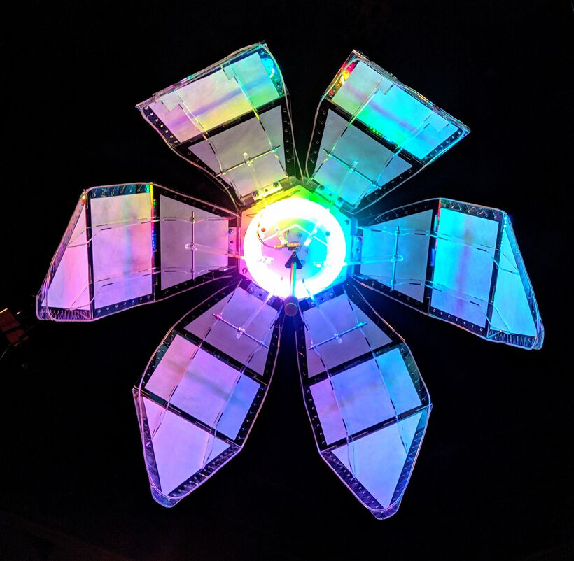
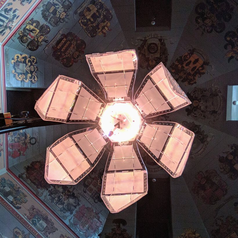
I quickly made a temporary adjustment to the code to keep the NeoPixels off as it opened and turn blue as it went into the “Fully Open” state, because it just looked so amazing when seeing it from below on video (the little red blip at the end is the end stop LED we later realized):
Some more shots of the lamp in its various stages:
And Douwe turned it all into a really awesome video (we called our lamp “Flo”), that we presented during the Regional and Global reviews:
Reflections
Every “machine” week I think that well, I can’t possibly spend even more time on my project than I did this week, and every time I’ve been proven wrong by the next machine week ಡ_ಡ This week was no different. From the first Thursday till the next Thursday, I did nothing else than work on this lamp. Brainstorming how it should look, designing it, prototyping it in cardboard, putting it together, and creating the lamp from acrylic. Of course, everything just takes more time and more errors than you expect at the start.
Then on the last two days before the final presentation I had to make sure that the lamp was actually programmed, only being able to use Loes' NeoPixel routines, and Henk’s stepper motor example, but having to figure out the rest on the spot.
What went wrong
Well, enough went wrong, but the biggest thing is probably that I wasn’t able to figure out how to make the ESP32 talk to the Arduino (correctly). I only had a few hours to learn this / figure it out, and I must’ve done something wrong, or misunderstood something (>﹏<) I’m really sorry that this meant that Douwe’s Bluetooth sniffing program couldn’t be used.
Initially I wanted to incorporate an origami/paper approach to cover the bottom of the lamp’s petals. However, I failed to get a good origami pattern working. I therefore decided to try and continue with exploring ways to properly use a machine to pre-cut/etch the paper in the “Wildcard Week”.
I also had things going wrong with that first acrylic plate somehow changing thickness substantially along its sides, and taking me an hour to figure it out. That we had to keep both the 12V adapter connected to the CNC shield of the Arduino and the 5V adapter into its USB port to make the lamp behave normally. That the wiring was just one big mess and we only barely managed to hide most of it. That I could only manage to program a few basic states of the lamp responding, and not using all of Loes' NeoPixel functions. That the lamp sometimes started twitching when we finally hung it in a dark room, while I didn’t know why.
What went well
We had a functioning lamp in the end! Ok, it behaved rather simply (mechanically), only reacting to light, but still, it was doing all that on its own. So I’m pretty proud of having made that, especially knowing that 10 weeks ago I wouldn’t have even known where to start.
We also managed to reach our goal of getting an “ooooooooohh” from Neil (๑•̀ㅂ•́)ง✧ (well, that was my goal anyway, haha)
What I would do differently
I should’ve realized sooner that in the end, even though I was in charge of the construction of the lamp, and had no programming tasks assigned, that I would be doing most of the programming, and thus that I would need to be the one that had to connect the Arduino to the ESP32. Perhaps if I’d taken an ESP32 dev board from the lab and my own Arduino along on the 4 days I took a break in the 2nd week, I could’ve made it work.
Although I think it would’ve been smarter if I’d taken up some task related to programming, and then also took charge of bringing it all together, from the start of the project, I just really wanted to design the lamp itself. I actually already knew this decision would come to bite me during the final days, but I still decided to take this route.
Wrapping up
In all honesty, I did too much on this lamp. The tasks ended up being weighed very unevenly. Especially when it became clear that, besides the creation of basically the entire lamp’s exterior itself, I also had to pick up a large chunk of the programming, even more so when I never received whatever Nicole did on the motor programming. These weren’t two healthy weeks for me, both physically and mentally.
Nevertheless, I had a lot of fun working together with Loes during our lab days! It was easy to hop between both of our tasks, and help the other out using things we were both more skilled in. And I’m damn proud of what we managed to put together! (⌐■_■)
All Files Together
You can read all about the specifics of what my fellow team mates did on their own sites: Douwe Schmidt, Loes Schakenbos, and Nicole Bakker.
And finally, see a short summary of this week on our Group Page.