Electronics Production
For this week's group assignment, our group needed to characterize and test the properties of a Roland SRM20.
Spindle Speed: Rotation frequency (degrees or revolution per unit time)
Plunge Rate: Rate a which endmill lowers into stock when cutting (distance/time)
Depth of Cut: Total distance to cut into stock (distance)
Tooling: The process of designing and engineering tools used to manufacture components
Roland SRM20 Specifications
Work Area: 8" x 6" x 2.38"
Loadable Workpiece Size: 8" x 6" x 2.8"
Table Size: 9.14" x 6.17"
Max Tool Size: 1/4" or 6mm
Spindle Speed: 3000-7000 rpm
Operating Speed: 1.18 in/sec or 30mm/sec
Mechanical Resolution: 0.00008in or 0.002mm
Acoustic Noise Level: 45-65dB (A)
Computer Interface: USB
Computer OS: Win 10, 8, 7
Computer OS: 32 or 64 Bit
Size: 18" Wide x 17" Deep x 17" Height
Weight: 44lbs
Power: 110V / 2.5A
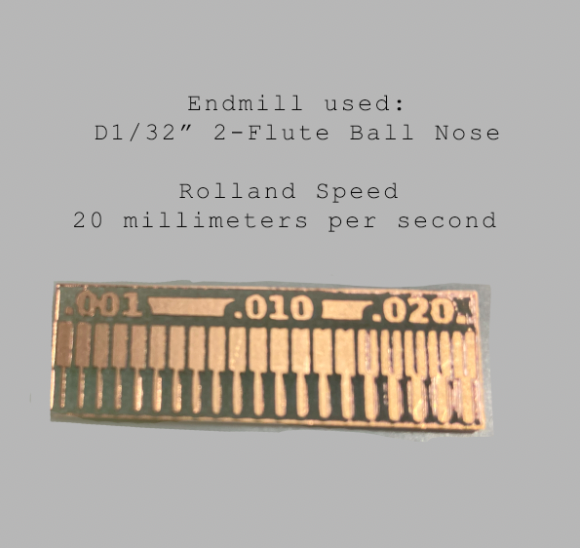
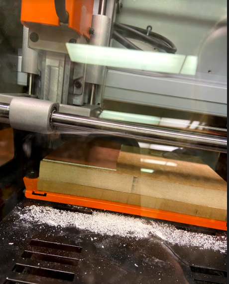
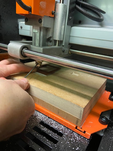
Rolland Endmill Test Cut
We Decided to go a little extreme and test what would happen to our test cut putting the Roland speed at 20mm/sec. As shown in our diagram… it did not cut that great.
Creating my Module in MODS
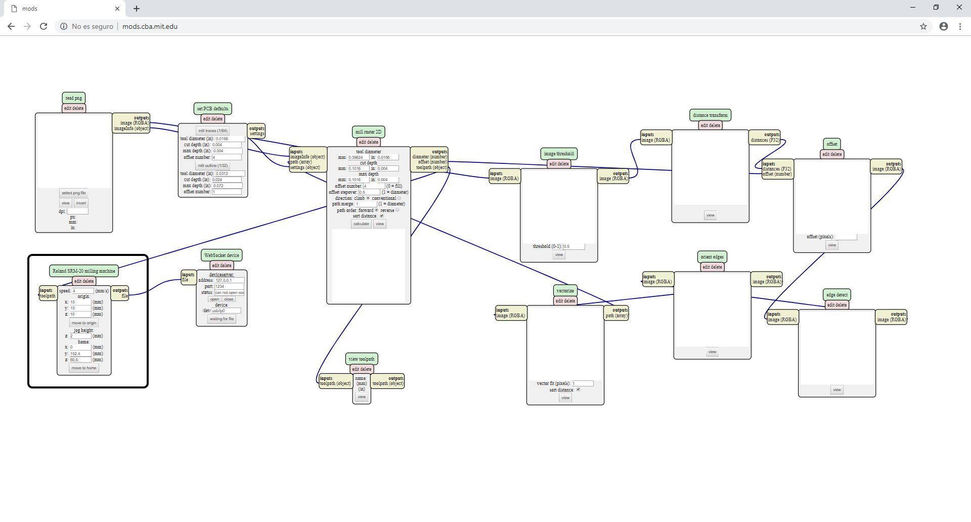
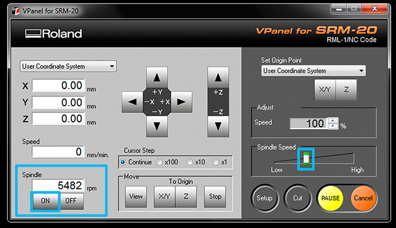
Creating my Trace Image In the program MODS I Select ROLAND > MILL > SMR20-MDX20 , PCB then I Right clicked in the white space and select MODULE > OPEN SERVE MODULE > SAVE FILE . Next I connected the elements by clicking on OUTPUT of RolandSrm-20milling machine and clicking again in the INPUT of the save file module to make the connection/ wiring between them. After that was completed I opened my image traces file so I would be able to form wires between my components. I first went to READ PNG MODULE SELECT- PNG FILE - to select my traces image. Then I needed to set my PCB default 1/64 MILL TRACES since that was the size of my bit. Next in Mill Raster 2D module I clicked Calculate. This saved my files automatically. I set my origins In module Roland SRM-20 milling machine at:
x0(mm) - 0
y0(mm) - 0
z0(mm) - 0
zjopg - 12
Speed - 4 mm
We turned the speed way down to the recommeded speed, instead of the 20mm/per sec we had tested in our group.
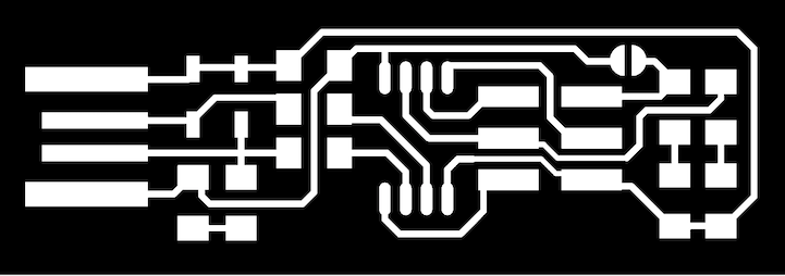
Here is the png trace I used.
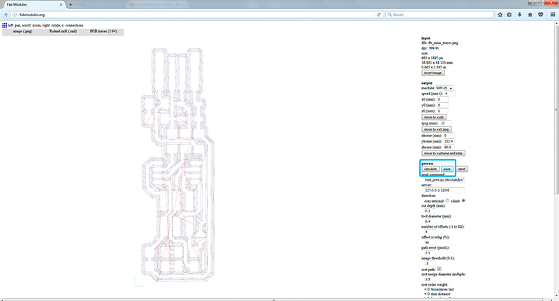
Here is how I was able to preview my trace pathway before saving to my downloads

I downloaded the outline cutout design png and SET PCB Default module by clicking in MILL TRACES 1/32. Then In Mill Raster 2D module clicked in Calculate. I made sure the coordinates read x0(mm) - 0
y0(mm) - 0
z0(mm) - 0
zjopg - 12
Speed - 0.5
I then exported my design files from my laptop into a memory card and plugged in into our computer connected to the Roland.
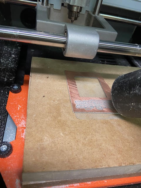
Next I turned on the Roland Modela and opened up VPanel for SRM-20. While the roland was warming up I got my board blank ready. I attached double sided tape to the back side of my copper board blank making sure it was EXTREMELY flat, with no bubbles or bumps.
Then I felt around to find that flattest part of our “sacrificial board” to place my board blank. The sacrificial board is the piece of wood secured on our machine to protect the machine from getting damaged if we were to mill too far down into our material.
Then I placed my board blank onto the sacrificial board and pressed down to secure the board.
Then I set my X/Y origin in Vpanel by using the x/y arrow keys and then selecting Set origin X/Y in Vpanel.
To sent the Z to zero I first had to screw in my mill bit farther up into the collect screw shaft and then Move the Z slowly with the control panel around 3-5 mm above the PCB plate. Then manually I loosen the collect screw and land the end mill on the surface.
Slowly loosen the mill bit with an allen wrench so that it drops gently to the surface of your board. Then re-tighten the end mill with the screw on the collet.
I saved the Z origin in the control panel.
Uploading my Traces PNG Design
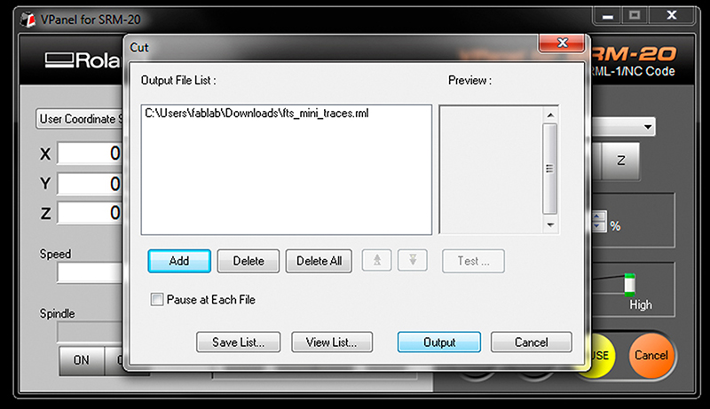
I selected “Cut” on the control panel. A new window appeared where I selected my trace cutting file, then I clicked on Output and the machine started cutting.
After the Roland stopped I vacuumed up the cut dust to see my traces. .
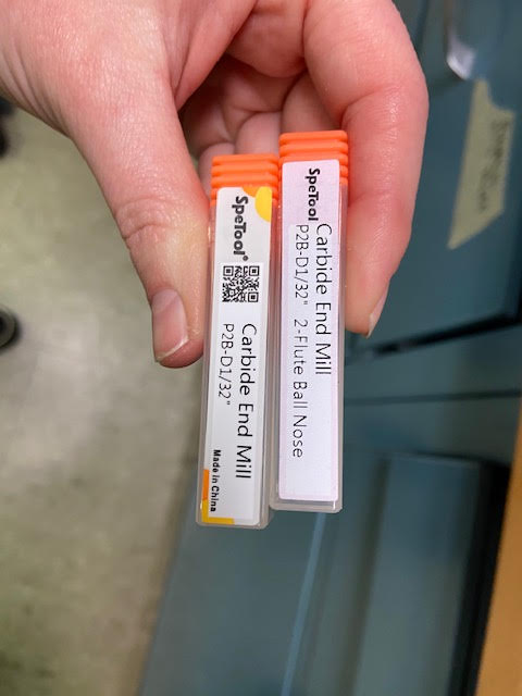
Then I had to switch out my end mill size to the 1/32 end mill. I repeated the Z origin procedure and selected “Cut”. Then I selected my outcut/holes file and clicked output in Vpanel
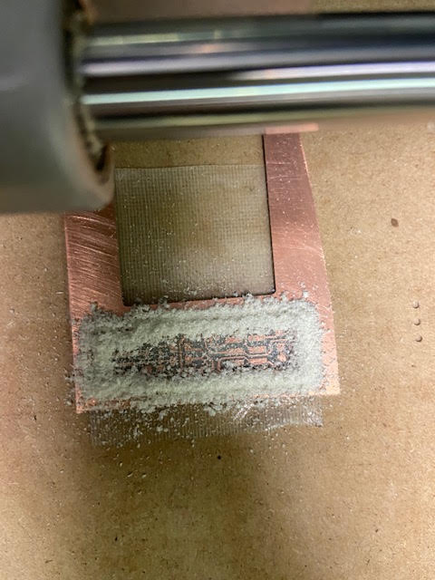
Here Is my cut right after the Roland finished!
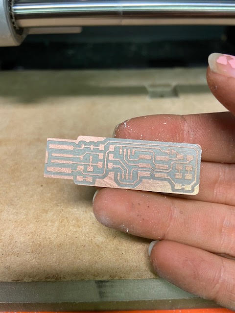
I next removed the dust with the vacum I pealed off the tape.
Building the FabTinyISP
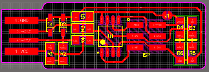
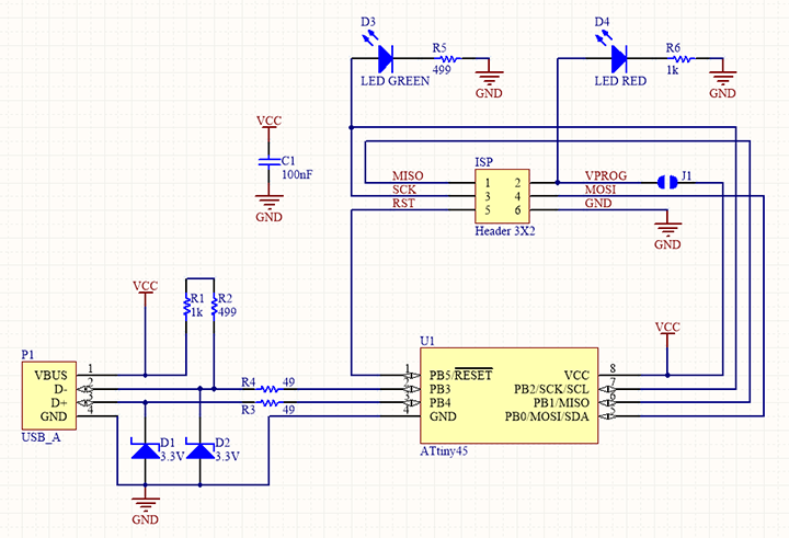
I used these to templates to follow where to solder each of my board components
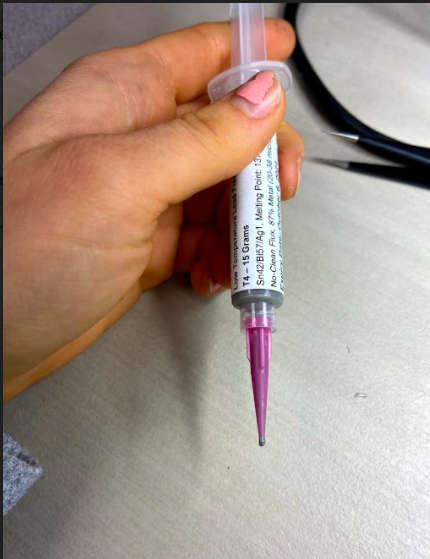
I used this solder in a syringe to adhere each component to my board. After adding a small dot of solder on my board in the location based on my template to place my component, I placed my component using tweezers to that specific location. Then I applied the heat gun to melt the solder and permanently adhere the components.
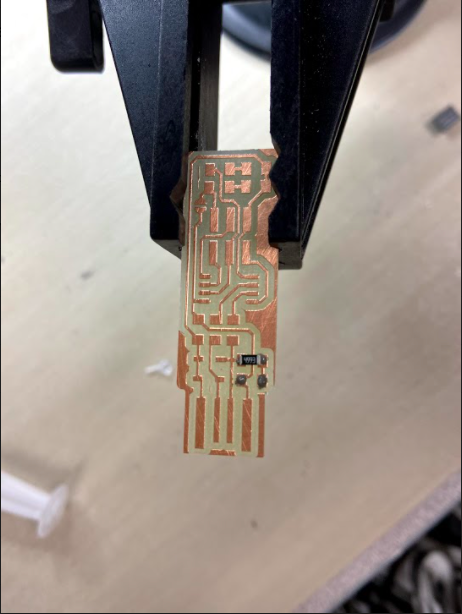
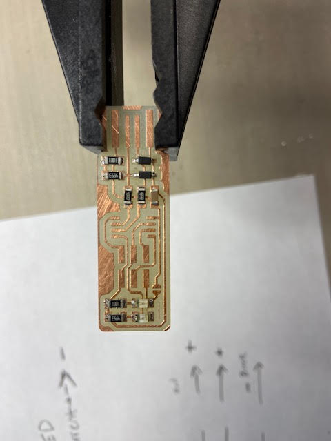
Here I placed my first components onto my board
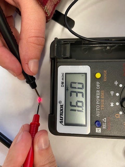
Here I used a multimeter in the diode check mode; to determine the positive and negative end of the LED. The LED glowed slightly when the red probe was on the anode and the black probe was on the cathode.
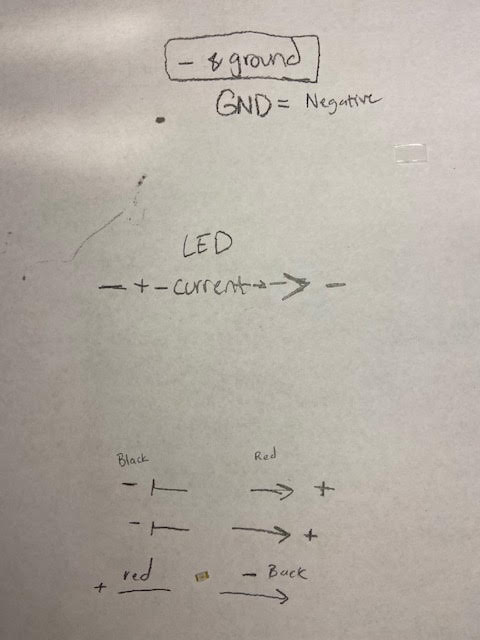
I also created this sheet to place my LEDs on to remember which way they where supposed to face before I adhered them to my board
All my components and LEDS on! I had only one mishap where I accidentally bumped my board and two components bumped off.
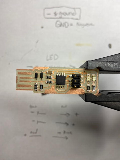
All parts on! after this I added the solder to the end strips that create the usb connection.
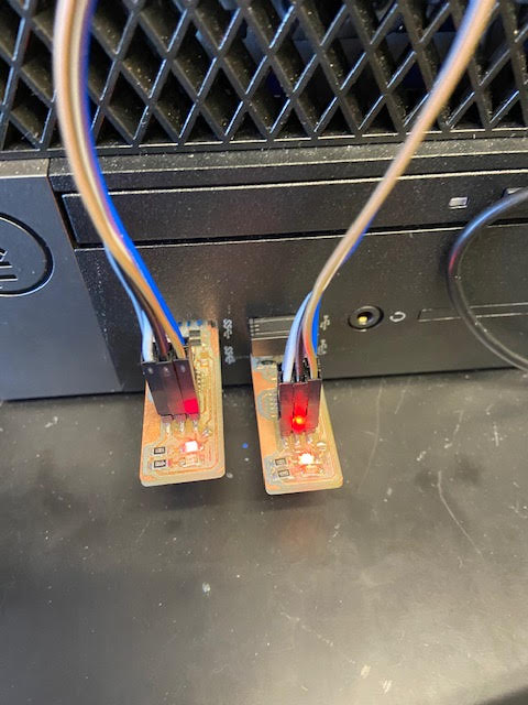
Then we pluged our boards in to check if the LED light would turn on, it did!
Programing FABTinyISP
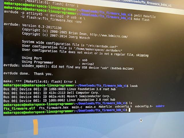
I enter the code sudo apt-get install avrdude gcc-avr avr-libc make into my schools Linux computer. Then I Download the firmware source code and extract the zip file (on Linux, unzip firmware_45.zip). I then ran make Once the command completed, a file called fts_firmware.hex appeared

Then I Edited the file called Makefile under the gedit command line and entered usbtiny since that was the device I was using to transport the code from another board onto my board.
I plugged my board into the USB port, and then also connected the programmer to the ISP header on my board. I made sure all the wires aligned identically in location to the board I was pulling the code from.
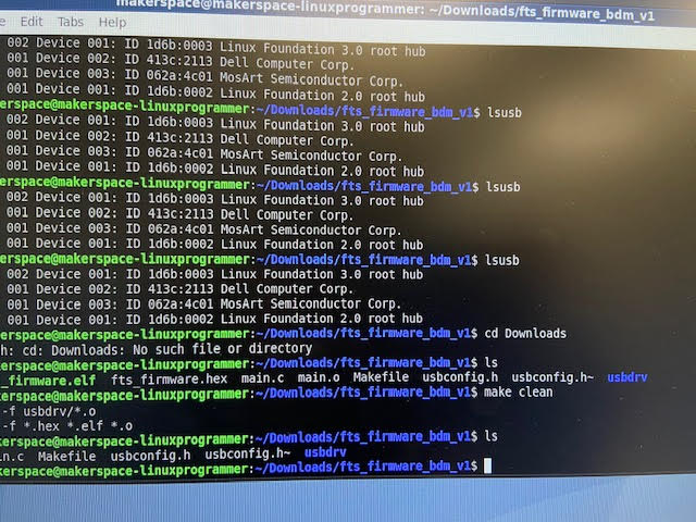
I Ran make flash. This erased the target chip, and programmed its flash memory with the contents of the .hex file. Then in the terminal we typled lsusb At this point, My board along with 3 other people in my class's board was not programming. Once we called in our expert programmer on campus He released the board we were using the program each of our boards with was acting finicky. Once we got a board that was programmed and working properly all our boards were able to be properly programmed.
Here is the link to my project files link here!