EMBEDDED PROGRAMMING
This week I programmed my circuit board in a variety of different programming languages and environments.
In Week 7, I designed and built a PCB. Now I'm working on programming it to do interesting stuff.
The assignment:
- Compare the performance and development workflows for different microcontroller families (in groups).
- Read the datasheet for the microcontroller you are programming.
- Program the board you have made to do something, with as many different programming languages and programming environments as possible.
Group Work
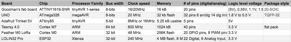
During our Thursday lab, the class worked in a group to identify different boards, along with their performance information and processor families. From researching the board manufacturers and studying datasheets, we were able to put together this information, on what each board had in terms of processor families, clock speed, memory, and more.
Additionally, we programmed several of the boards to run the standard Arduino "Blink" sketch. We found instructions on manufacturer websites on how to program a board. For many of them, we needed to install the right Board Manager after adding its URL in the Arduino IDE preferences.
Then we went to the Tools dropdown menu to choose the correct board that we were using. We had some issues with some boards not showing up when we tried to select a port, but other boards worked, and we were able to get the Blink sketch working a couple of different processing families.
Here is the Teensy 4.0, from the ARM family, running Blink.
And here is the RedBoard UNO, from the AVR family, doing the same.
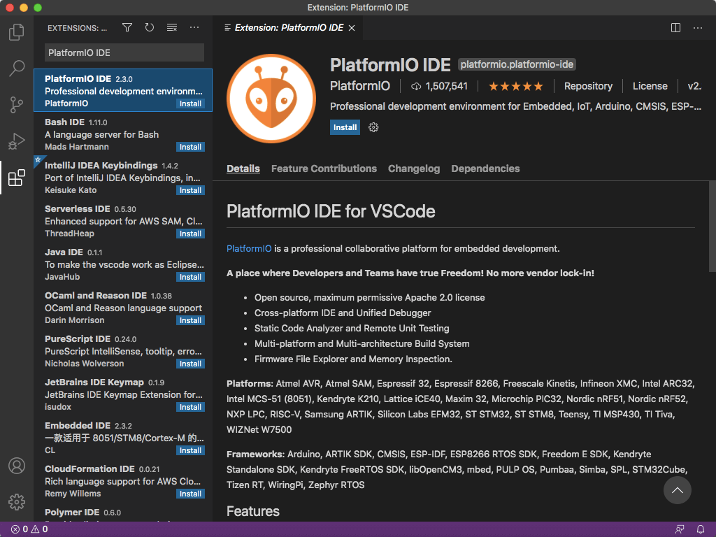
This was all done in the Arduino IDE (integrated development environment). An IDE is a software that contains tools for writing and debugging code. Another IDE that Professor Goodman recommended for this week was the PlatformIO extension.
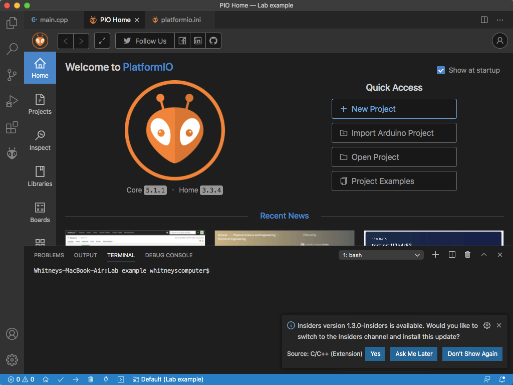
I downloaded Visual Studio Code and installed PlatformIO on it.
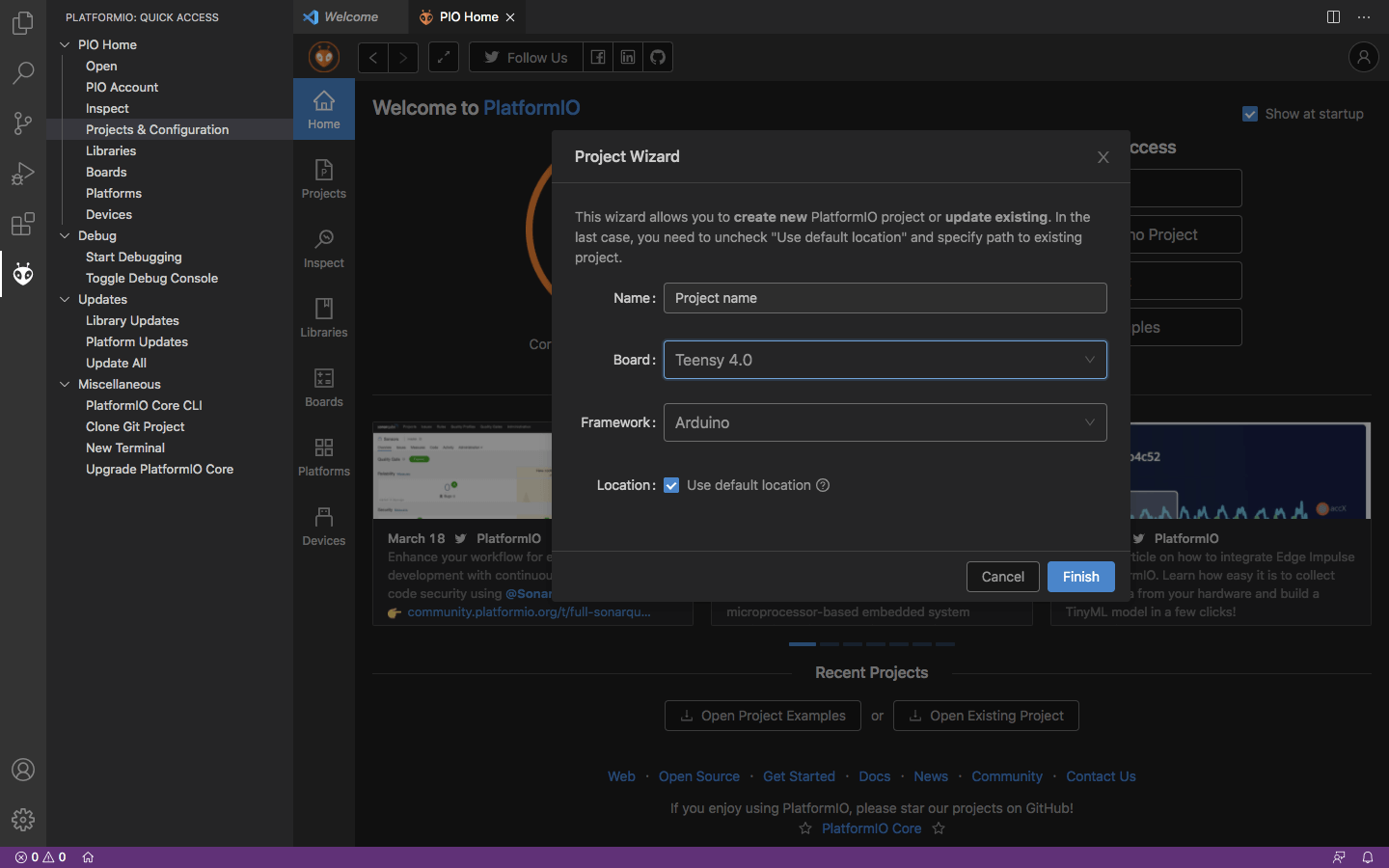
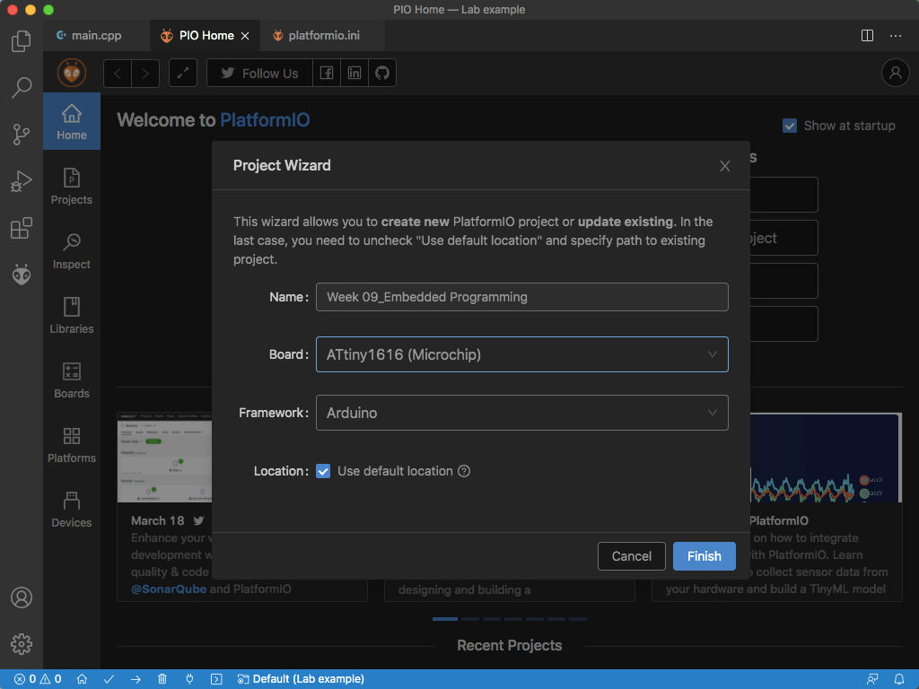
I recreated the Blink sketch for the Teensy in this IDE. Here it was easier to program the board, it that there were fewer steps to set it up. All I needed to do was create a new project and select my board from a given list.
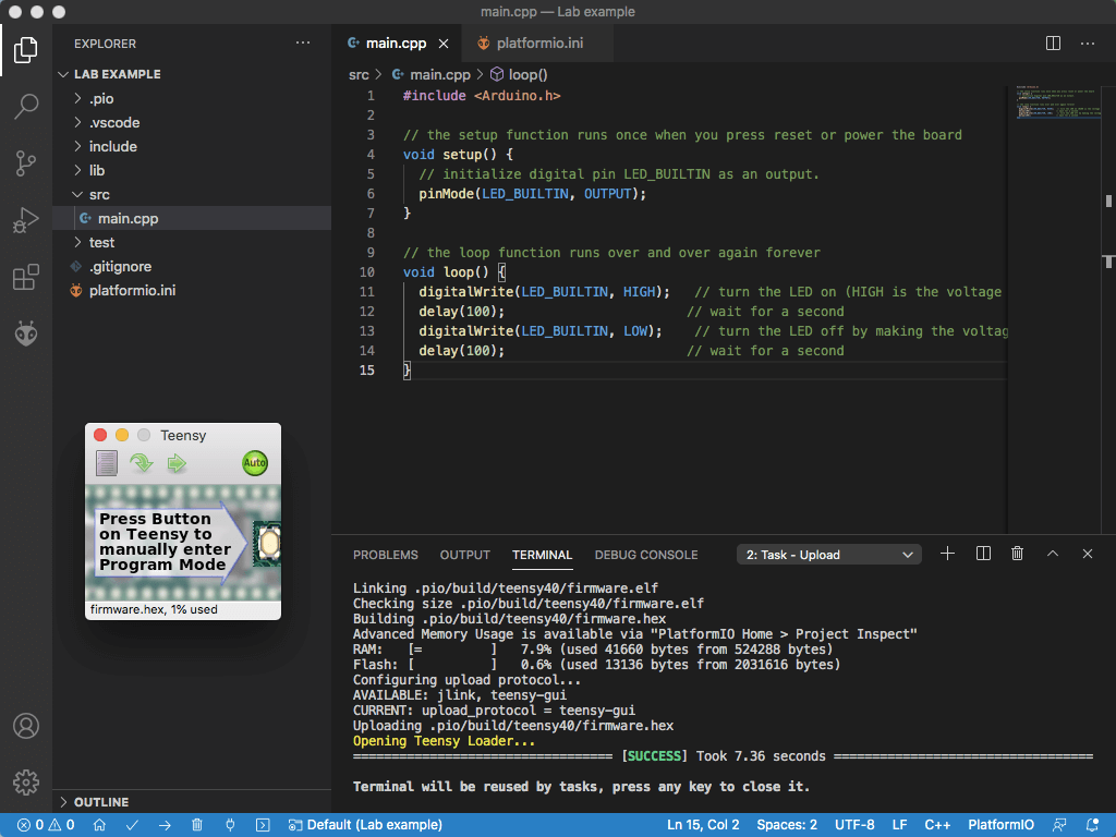
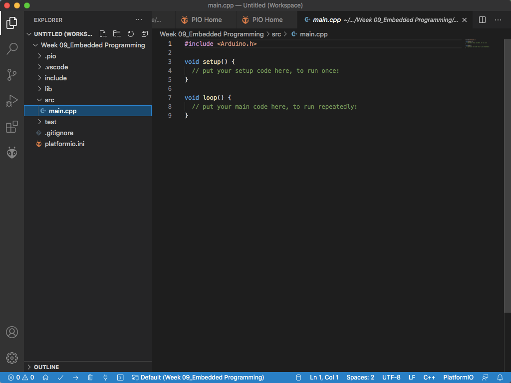
I copied the Blink sketch from Arduino into "main.cpp" and changed the delay times so I could see if the board was getting programmed by the code in the new IDE. This worked!
Next, we decided to try removing the delay altogether. This made the LED stay on continuously. Professor Goodman explained how without a delay, the LED is actually turning on and off at the board's clock speed. We used an oscilloscope to compare the operating speeds of different boards.
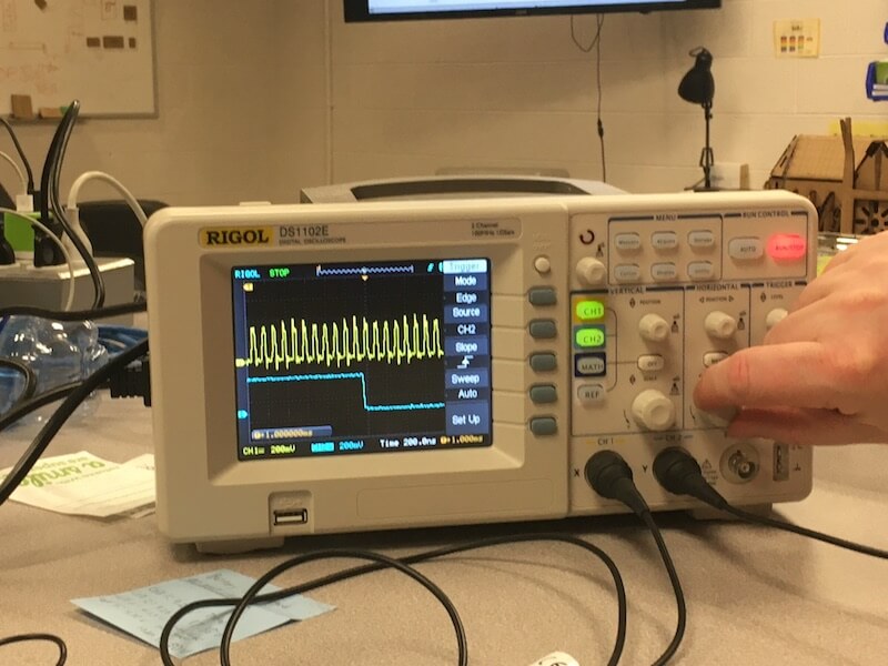
On the digital screen, we could see that the Teensy compared to the Feather was incredibly fast. The Feather was operating at around 1 million blinks a second, and the Feather was at 33 million blinks a second. This makes sense considering the Teensy's very fast clock speed of 600 MHz.
Microcontroller
One of the goals for this week was to start learning about the microcontrollers that we're using. To do this we can look at the datasheets for the ATtiny1616. This microcontroller is part of the AVR 1-series family and uses a flexible, low-power architecture.
Here are some of the important features of the ATtiny1616.
| CPU | AVR® 8-bit |
| Clock Speed | 20 MHz |
| Flash Memory | 16 KB |
| SRAM | 2 KB |
| EEPROM | 256 bytes |
| Operating Voltage | 1.8V to 5.5V |
| Package style | 20-pin SOIC300 |
| I/O lines | 18 programmable pins (6 digital/12 analog) |
Programming
This week I programmed my board from Week 7, and more broadly, I learned about the processes for programming boards in different IDEs.
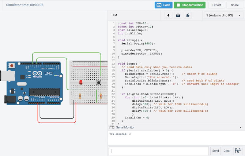
With one LED and a button on my board, I decided to write a code that would blink the LED a certain number of times after the user enters a number in the serial monitor and presses the button. I started writing this code in Tinkercad's circuit simulation space to test it out.
By the way, as Neil and Prof. Goodman explained in their lectures, Arduino is multiple things; it's a physical board layout, a C-based programming language, an IDE, and more. I be refering to Arduino as all of these things as some point.
Here I recreated my circuit board's components, using an Arduino UNO, and set up the basic structure of the code.
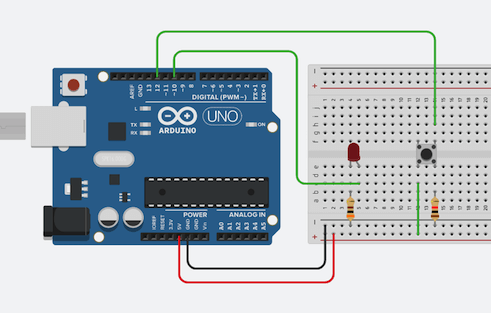
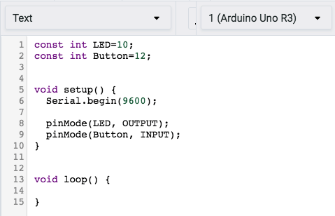
I made sure to assign the components to the correct pins and pin modes. "Serial.begin" tells the processor the baud rate at which to work. Void setup() will be run once when I upload the code, and Void loop() will repeat over and over.
Here was one of my early attempts at writing the code that would make the LED blink however many times. The issue with this was that the LED would continue blinking beyond the number that the user enters.
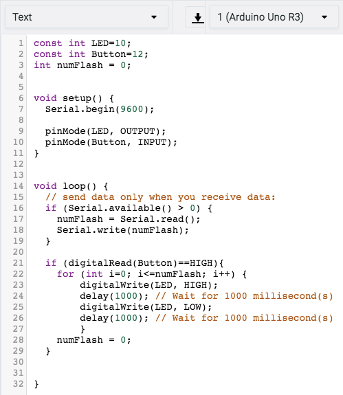
It turns out that I was using "numFlash" as the number of times to run the for loop, but I had stored that variable as a character input from the user. So, I converted the character input to an integer. I did this in a kind of funky way, by subtracting the letter zero. I also found out that there is a difference between "serial.print" and "serial.write", the former sends ASCII characters and the latter sends data bytes.
You can view my Tinkercad code in action HERE.
Arduino IDE
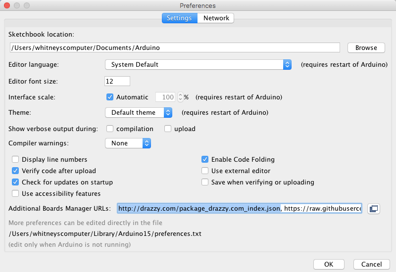
Next, I brought this code into the Arduino IDE and configured the settings to match my board type. Because I'm using an ATtiny, I needed to install a core that would run on my mircocontroller. In Week 7, I added the megaTinyCore by Spence Konde to my Arduino IDE.
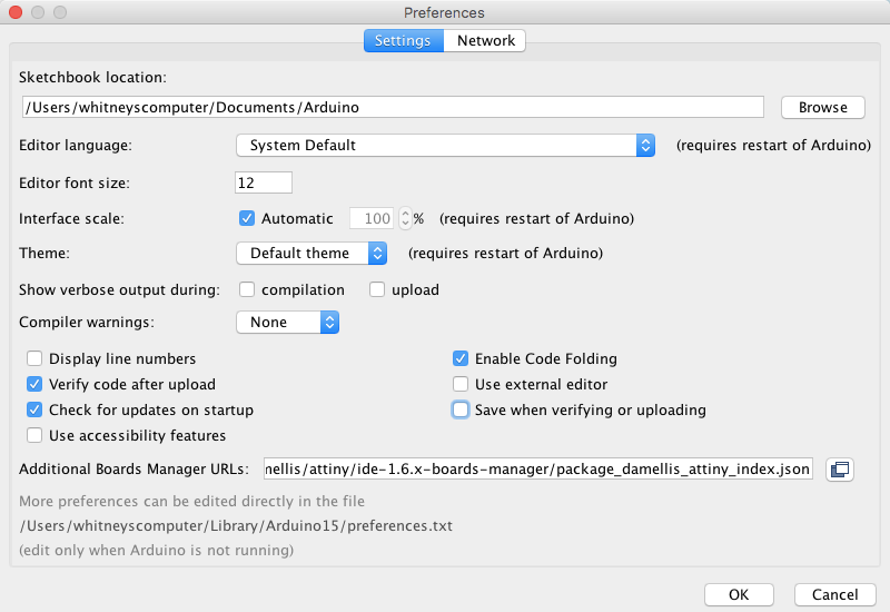
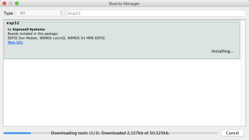
To do this, I went to Arduino > Preferences... and added an Additional Board Manager URL, which I got from the Installation.md instructions on the megaTinyCore's GitHub site. Then, I went to Tools > Board: > Boards Manager and searched for the ATtiny1616 to install the megaTinyCore.
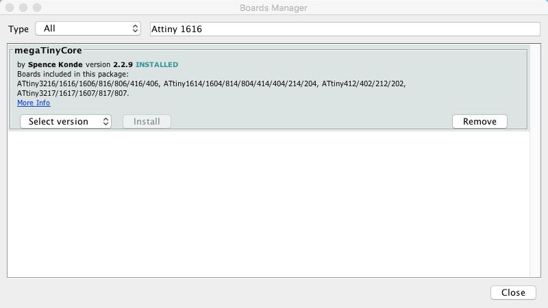
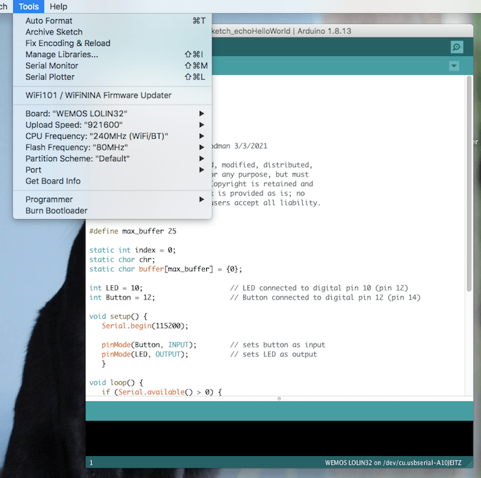
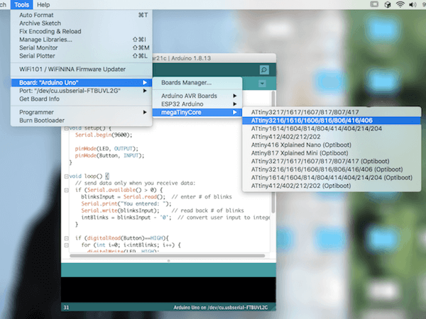
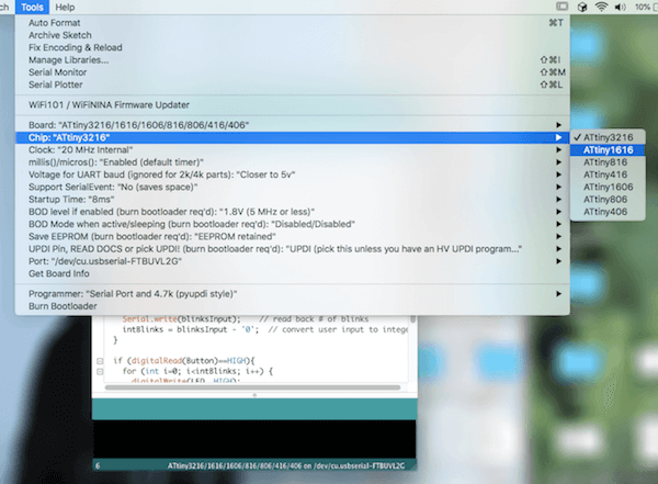
Once I had the core, I could find and select my board and chip from the "Tools" menu.
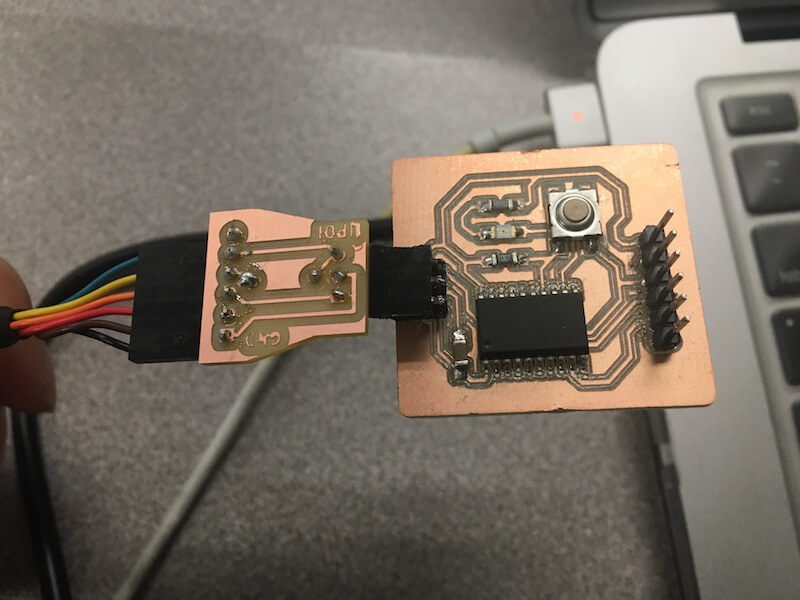
Then, I plugged my board's programming pin into the computer using an FTDI USB-to-serial cable, and an FTDI to UPDI adapter.
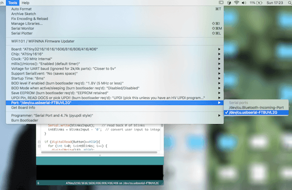
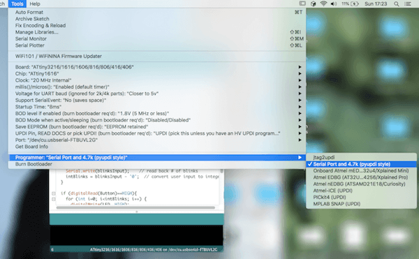
After that, I selected my port, the 'usbserial' one, and I chose the programmer. Pyupdi is a Python tool for programming AVR microcontrollers with a UPDI interface and serial port.
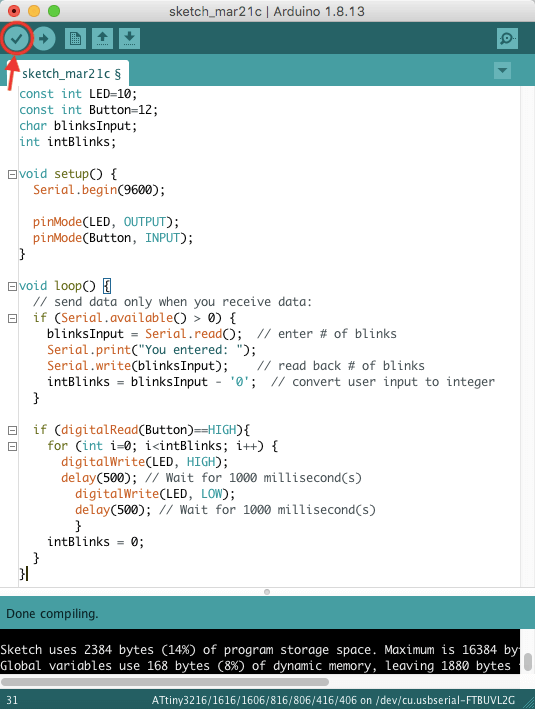
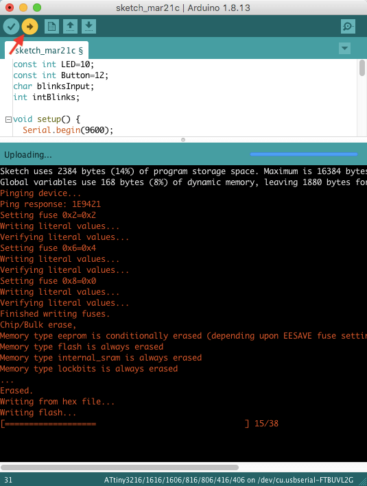
Now that I had my board hooked up, I compiled and uploaded my code. This went well, no error messages yet.
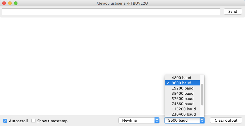
In the Serial Monitor, I set the baud rate to 9600. However, when I ran the code by entering a number, then pressing the button on my board, the LED flashed continuously instead of the input I gave it.
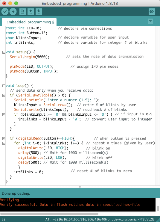
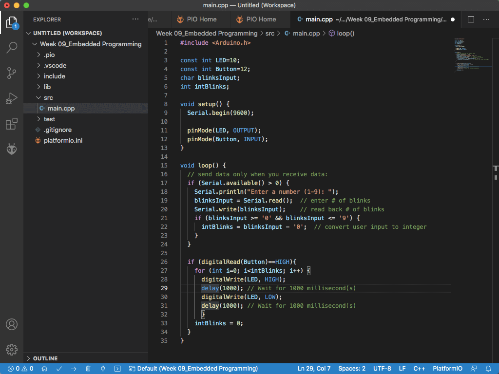
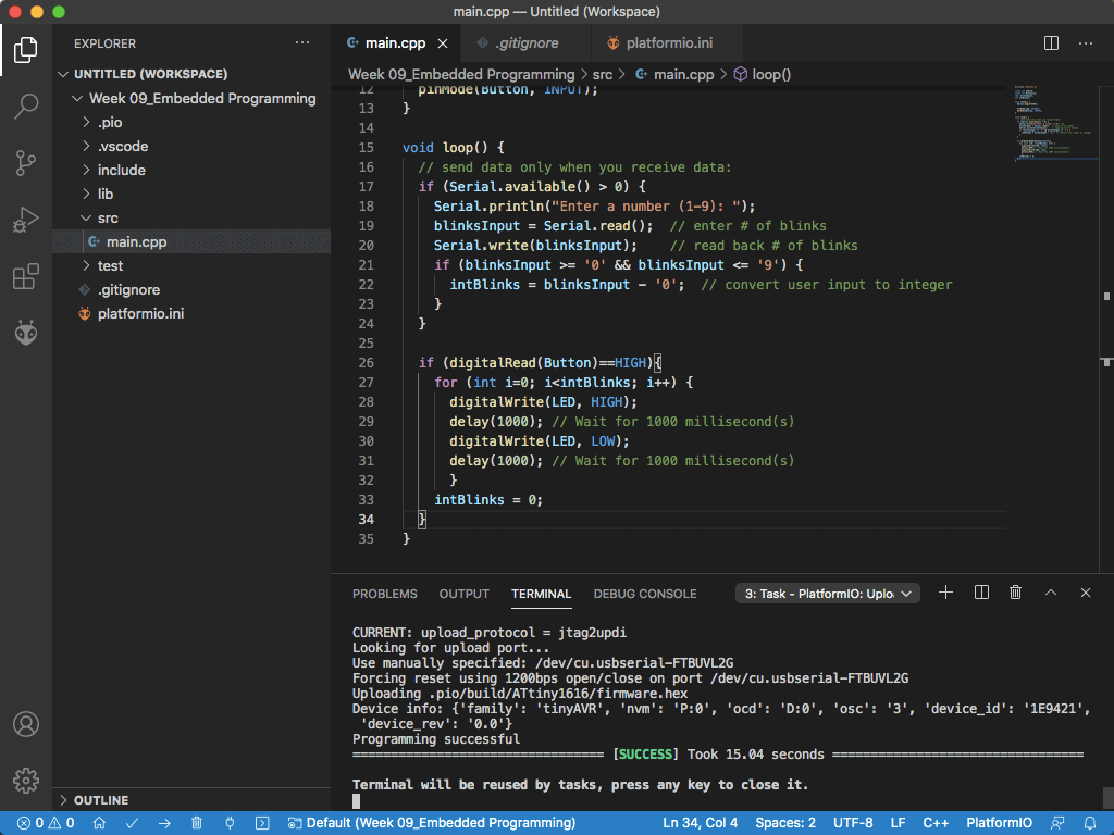
We think the issue was when I entered a number, the Arduino IDE was recognizing the return key as a newline character. I changed this and ran the code again, and it worked! As a reminder, this code will make my LED blink a specified number of times. That number is entered in the Serial Monitor, and the blinking will begin when the button is pressed. See the comments below for further explanation of my code.
PlatformIO IDE
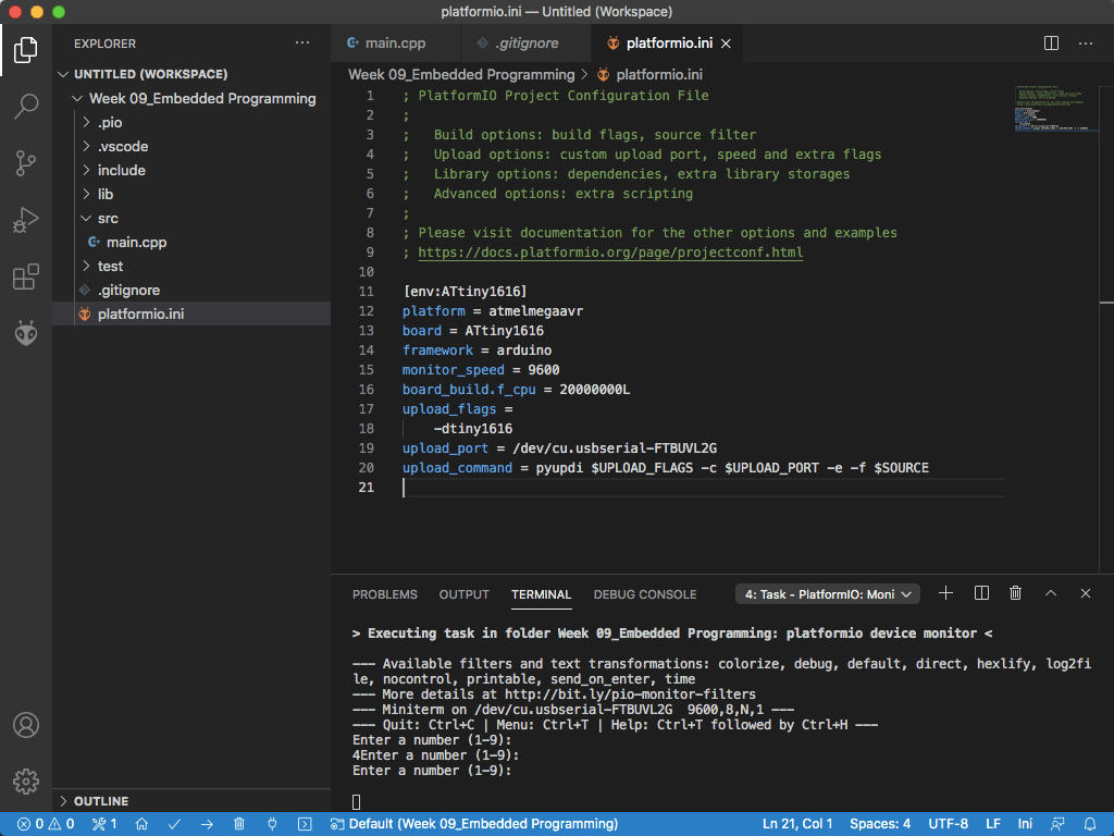
Next, I wrote the same code in C++ using the PlatformIO plug-in for Visual Studio Code. I had to download VSCode and install the PlatformIO from the Extention Manager before I began. From there, I could create a "New Project" where I selected the ATtiny1616 as my board with an Arduino framework. Under the file called main.cpp, I added my code and built it.

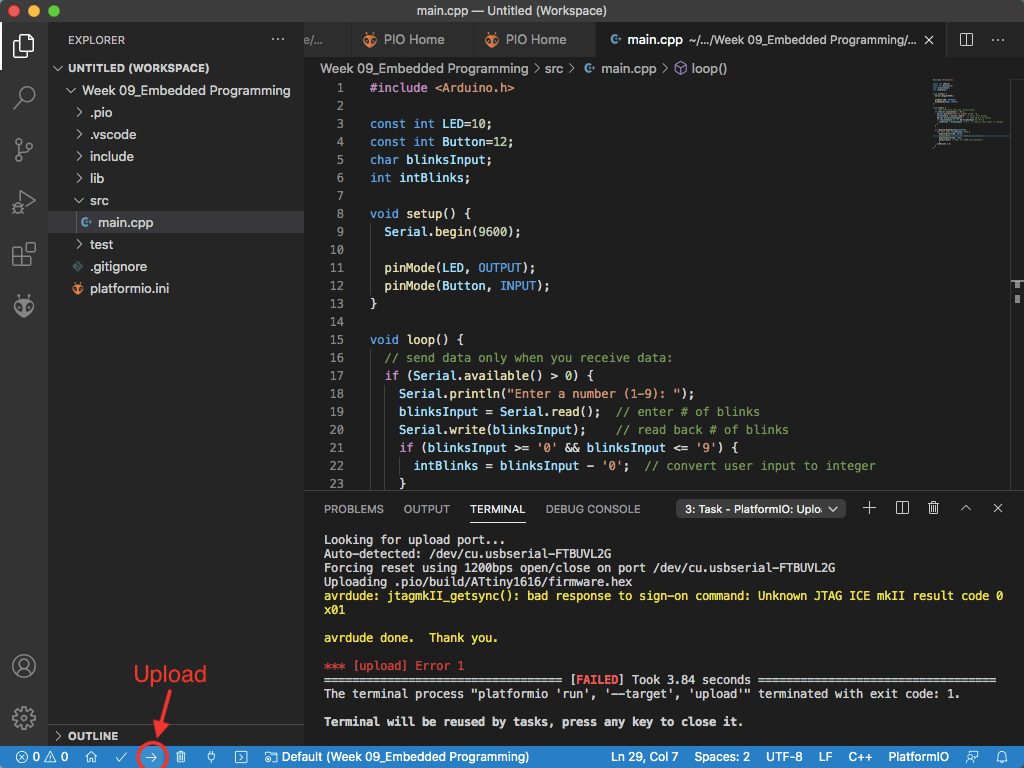
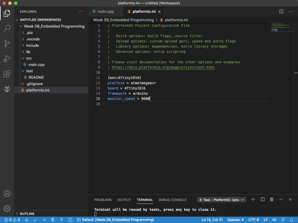
When I went to upload my code, I got an error message. The problem was that I had not installed the programmer, pyupdi. By referencing some installation instructions on a few different sites, I installed pyupdi using these commands in the terminal and by editing the platform.ini file to recognize the programmer and serial port.
$ pip install https://github.com/mraardvark/pyupdi/archive/master.zip
$ pyupdi -d tiny1616 -c /dev/cu.usbserial-FTBUVL2G -i
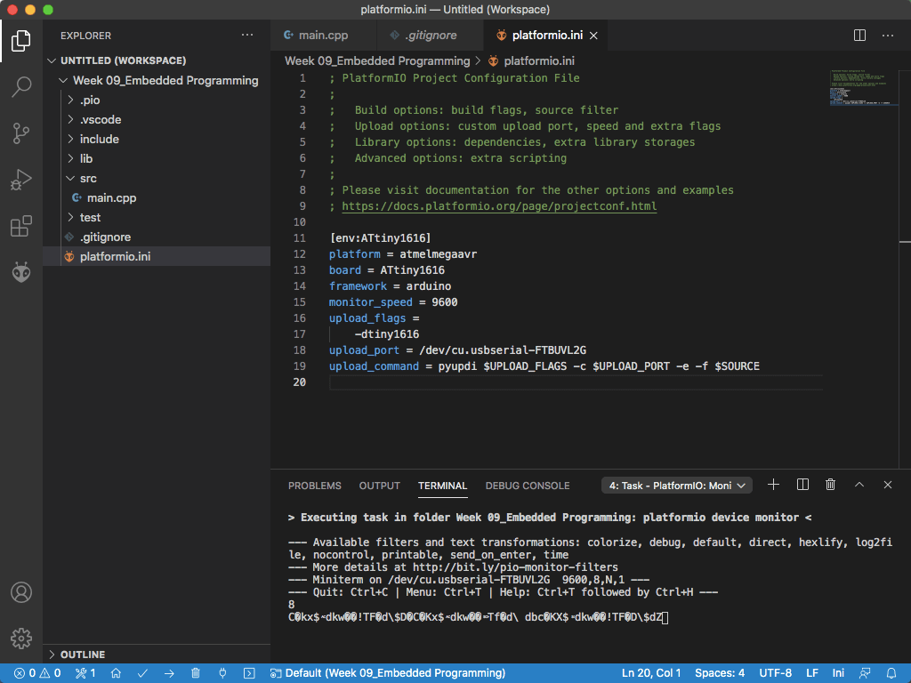
I was able to upload my code after making these changes, but when I entered a number for the blinks, I got a weird string of characters. Noah suggested that this was a frequency error, so I changed this by adding a line of code "board_build.mcu = 20000000L".
Finally, this code uploaded successfully, and when I entered a number into the serial monitor, the right input was read out.
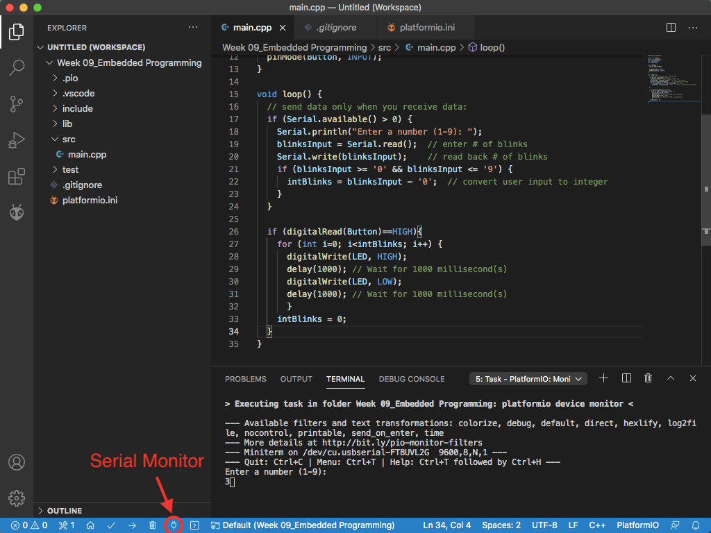
Then, when I pushed the button, it worked! In this example, I typed in 3 and the LED blinked 3 times.
This week I learned the processes for programming different microcontrollers. I used Arduino and C++ to create a simple program on my board, which I executed in the Arduino and PlatformIO integrated development environments.
Resources
- Datasheets: ATtiny1616
- Software and IDEs: Arduino | Visual Studio Code | PlatformIO IDE
- megaTinyCore by Spence Konde
- Installing Pyupdi: Programming the ATtiny 1-series (skip to INSTALL PYUPDI) | Configuring Atmel megaAVR
- PlatformIO help: Getting Started | ATtiny1616
- Coding References: Arduino Tutorialspoint C++
- Arduino Sketches: Blink, Digital Read Serial, Fade, Button, State Change Detection, Dimmer, Read ASCII String
Design Files
Updated: March 23, 2021