INPUT DEVICES
This week I learned about sensors and how to program them.
This was the assignment:
- Probe an input device(s)'s analog and digital signals (in groups).
- Measure something: add a sensor to a microcontroller board that you have designed and read it.
Group Work
During our lab, Prof. Goodman gave a presentation on input devices and three different ways to read a sensor.
- Digital inputs: these send either a high or low signal to the microcontroller.
Ex. switches, rotary encoders, passive IR sensors. - Analog inputs: these can send a range of data to the microcontroller through varying voltage levels. Ex. thermistor, potentiometer, phototransistor, Hall Effect sensor.
- Digital communications: this is for communicating between two microcontrollers. Binary data is being transmitted and received.
As a note, input sensors require either a pull-up or pull-down resistor. In order for the pin readings to not fluctuate, a resistor makes it so that the default state is either high or low, depending on if you used a pull-up or pull-down resistor respectively. In other words, a "pull-up" resistor pulls the voltage up to VCC, and a "pull-down" resistor pulls the voltage down to GND.
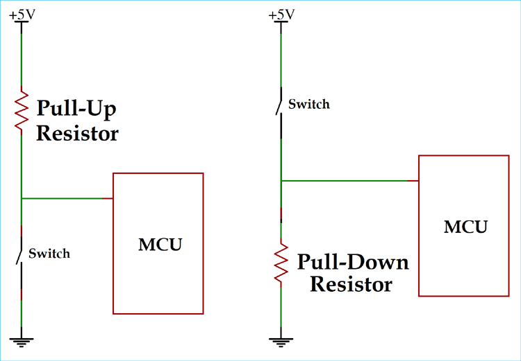
Some microcontrollers, like the ATtiny's I will be using, have pull up resistors built into the chip and they can be activated via the Arduino code.
Here's a little more description on some of the devices we have in the lab.
- switches - an on/off switch is a physical break in the electrical connection
- rotary encoders - a knob that can detect specific positioning and can rotate fully in either direction.
- PIR sensors - detects infrared energy, such as human presence.
- thermistor - changes resistance based on temperature.
- potentiometer - uses a voltage divider with a sliding connection between VCC and GND. Useful for scenarios that need a 0-100% range, such as volume.
- joysticks - these are 2 potentiometers placed on X and Y axes.
- phototransistor - changes resistance based on amount of light present
- Hall Effect sensor - detects if the flow of current is perpendicular to a magnetic field. This could be used to detect a turning movement in a specific direction.
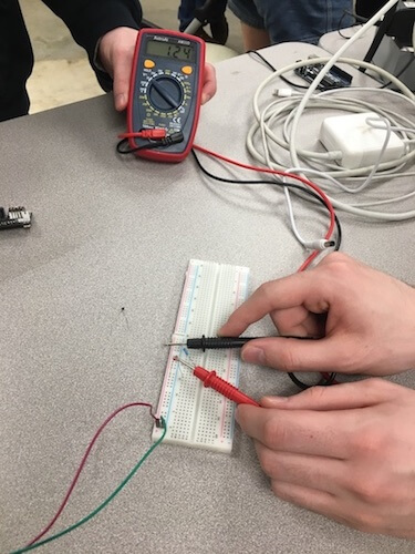
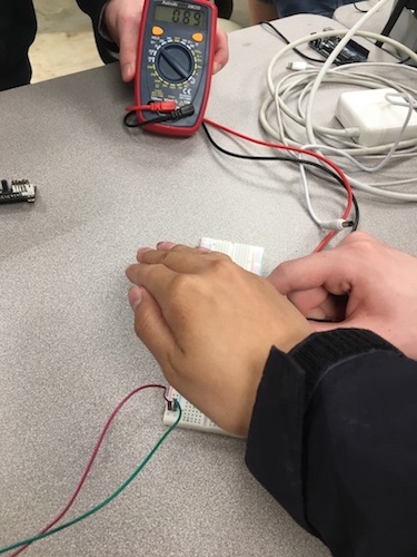
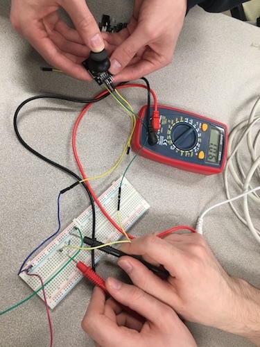
In my group, we tested a few of these input sensors. Below, we hooked up a phototransistor and pull-down resistor to the power and ground of a battery pack. When we covered the phototransistor with our hand and probed the sensor with a multimeter, we could see that its resistance and voltage values changed.
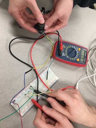
Here we tried this again with a joystick and the voltage changed when we shifted it.
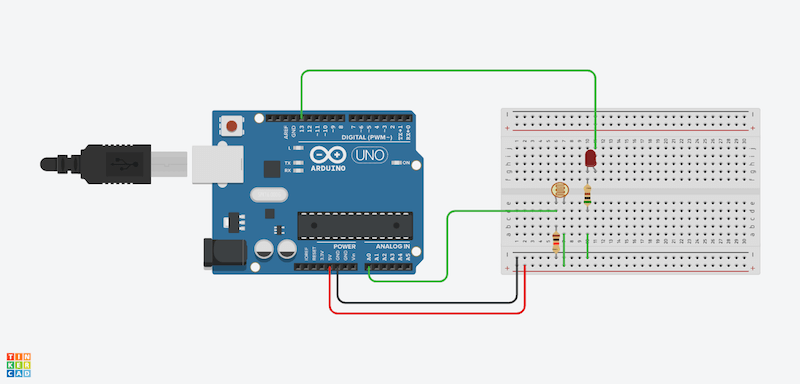
After that I used Tinkercad to model a circuit with an Arduino Uno and a phototransistor as an input device. As the brightness increases the resistance and voltage decreases. I've set the code so that the rate of the LED blinks changes depending on whether the sensor reaches a certain threshold. Click HERE to see my circuit in action.
Thermistor Sensor
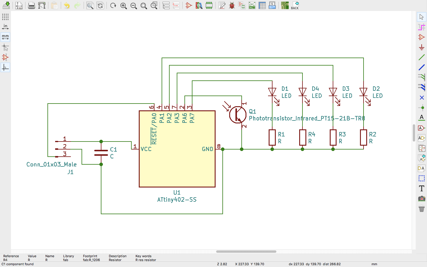
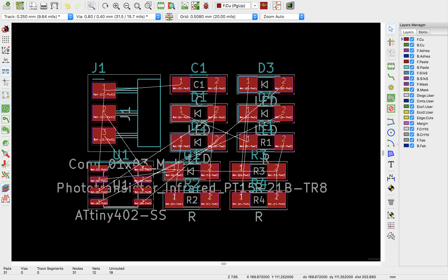
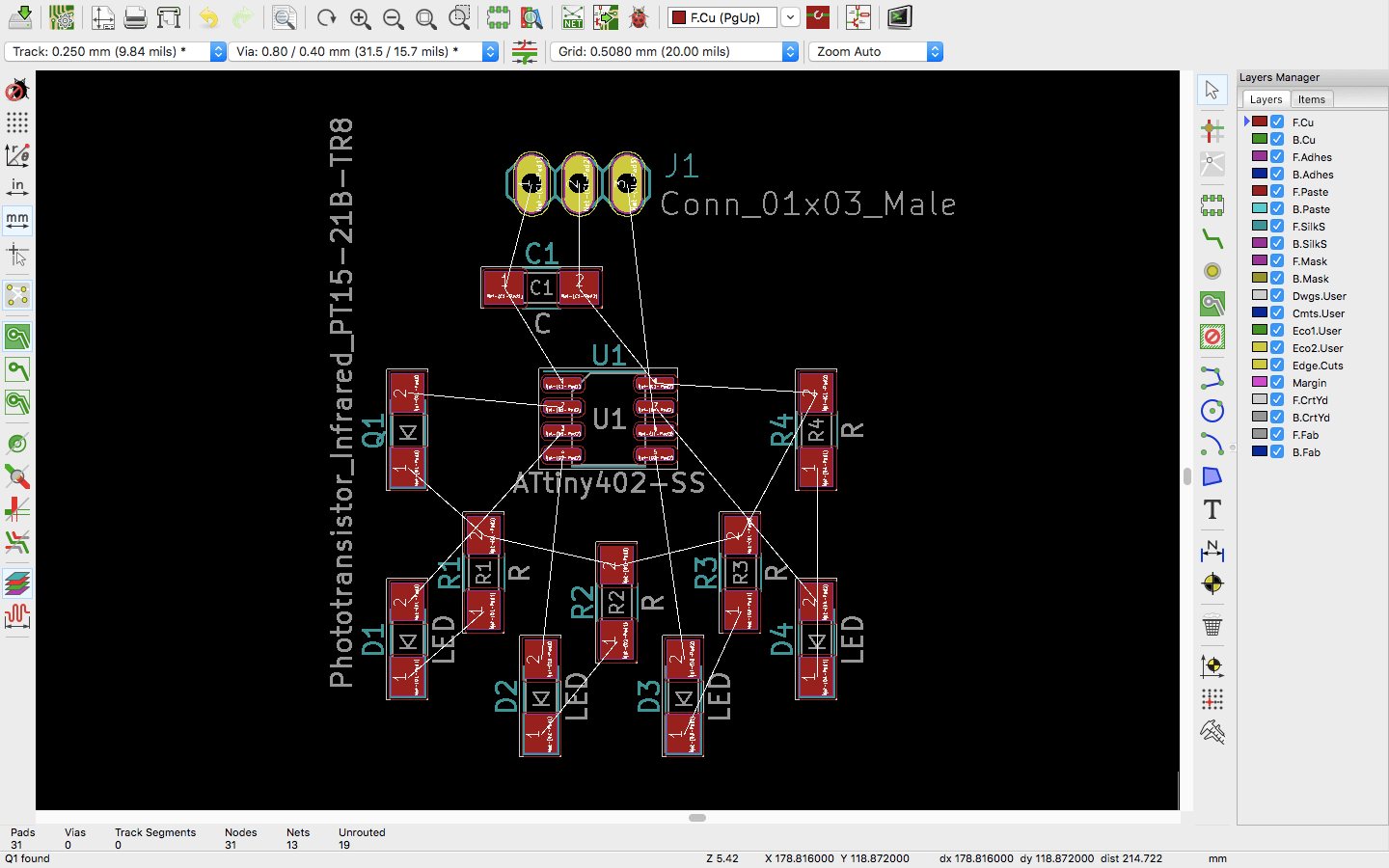
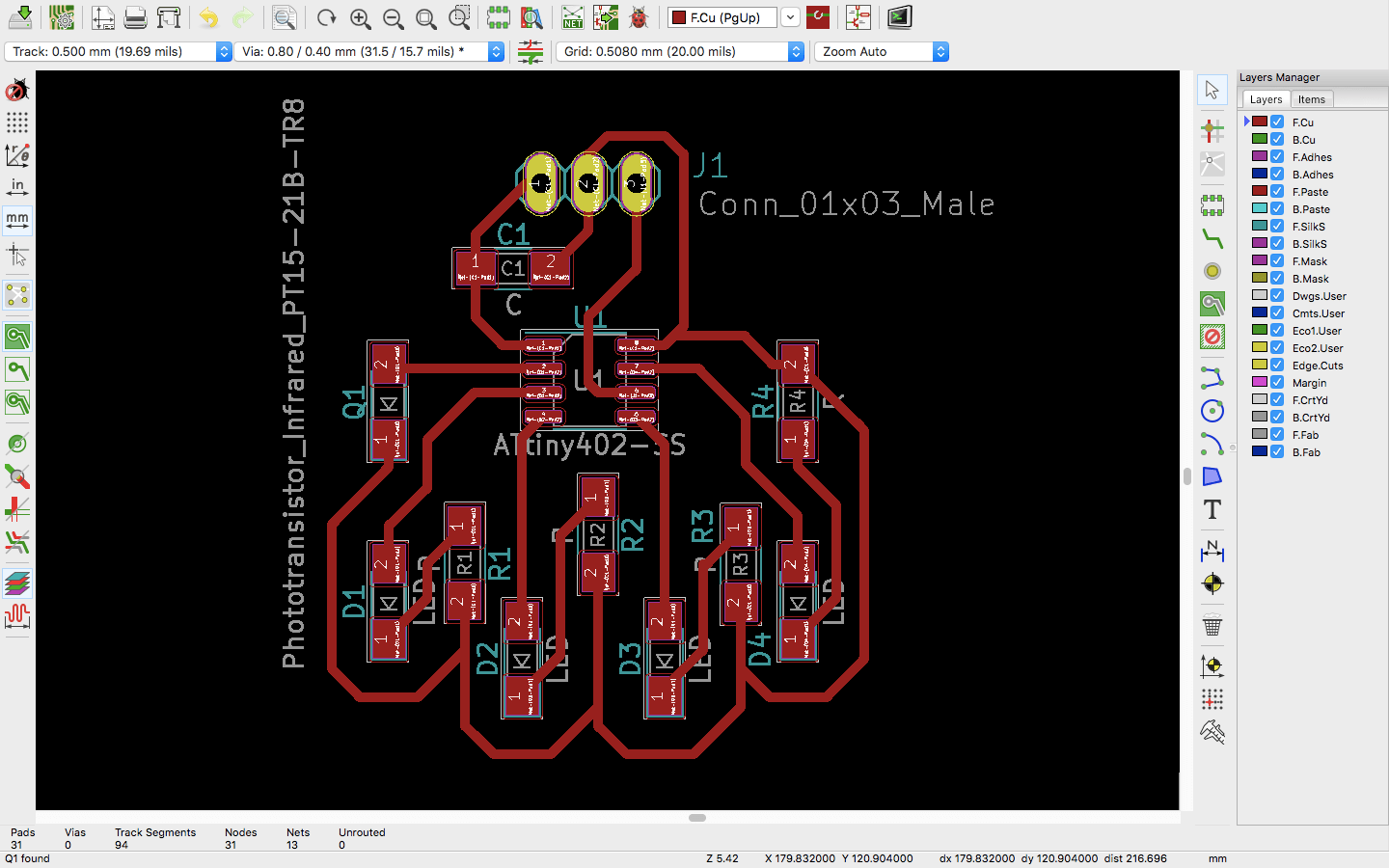
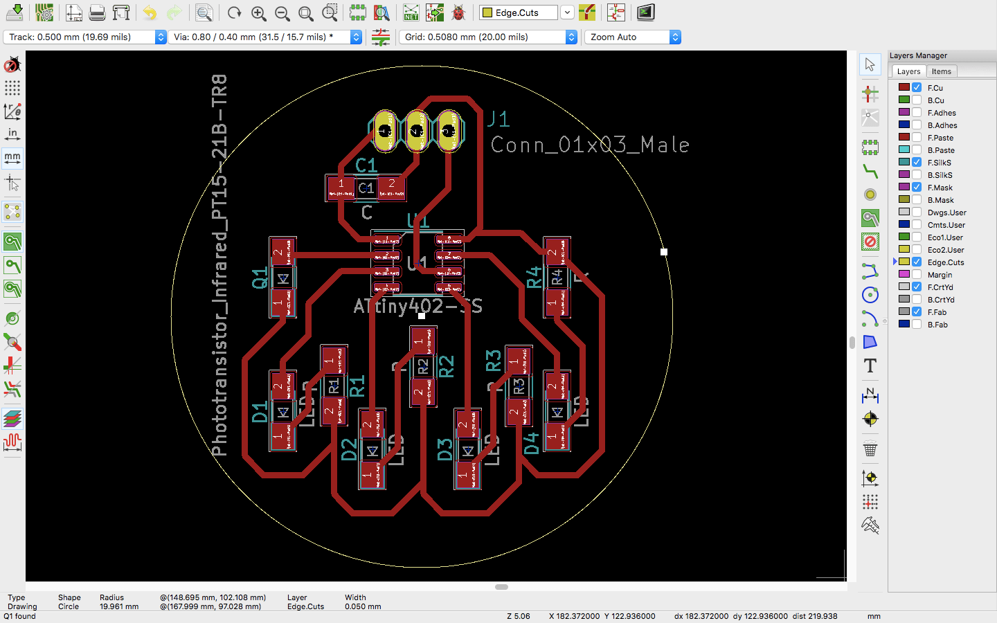
For my input device I used a thermistor which detects temperature. Here is the KiCad schematic and footprint diagram I made. The diagrams say phototransistor, but I decided to use a thermistor at the last minute. This worked out since the two have the same footprint.
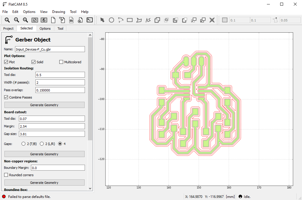
Next, I exported the Gerber files and set them up in FlatCam. I used a speed of 120 for everything, and -0.1 mm as the height for the traces and -1.61 mm for the outline and holes.
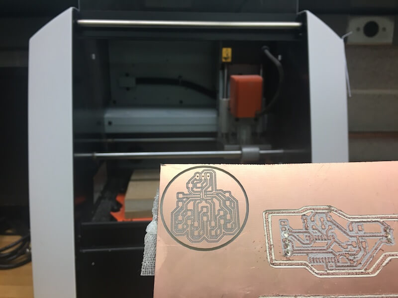
I generated the NC files from FlatCam and then prepared the Roland. As usual, I secured the copper board to the bed and used the 1/32" ball nose endmill to zero the origin. When I milled it, the traces came out very well, but the outline and the holes did not go through far enough. I had already removed the plate when I realized this, so I cut away the excess as well as I could.
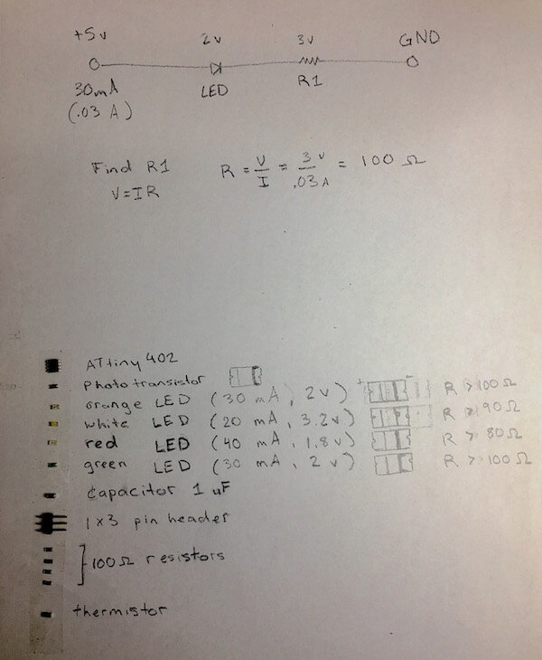
After that was soldering. I gathered up my components on a piece of paper that lists them all. For my chip, I used an ATtiny402. Here I am also making note of the components' polarity. All the LEDs have marks on the cathode side, and the thermistor sensor I'm using doesn't have a direction. (Ignore the photoresistor.)
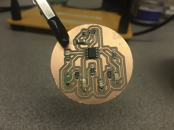
Here's my board after soldering. I switched out one of the resistors for a stronger one when I noticed the white LED was way too bright.
Programming came next. I used the Arduino IDE, and since I was using a new kind of ATtiny, I made sure to select the right tool settings.
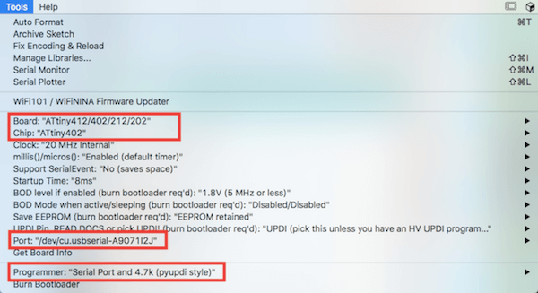
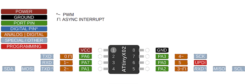
Here is the pinout diagram that I referenced. By the way, the ATtiny402 is made up of six GPIOs pins that can be used for either digital or analog devices.
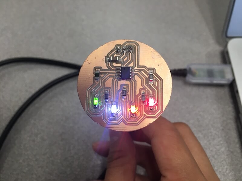
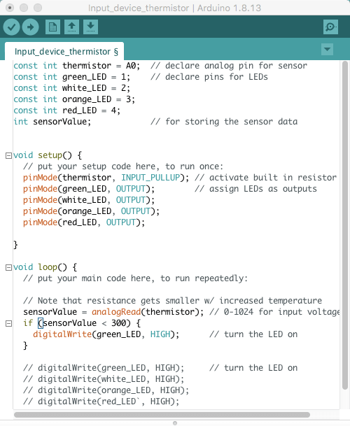
I set up my code with the digital and analog pin numbers assigned to integer constants, and I made all of the LEDs to be outputs. Just to test my board, I set all of the LEDs to high.
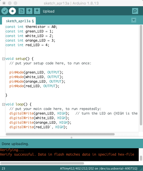
Something weird I found was that after soldering, the white LED would not turn on when I checked it with the multimeter, but when I removed it from the board and tested it again it worked. This happened with a couple of white LEDs, but I guess it didn't matter because when I programed my board, all of the lights turned on.
Next, to use the thermistor I created a variable to hold the sensor value and activated a built-in pull-up resistor. In the loop function, I used analogRead() to read the sensor and store its value as the variable I created earlier. After that, it was a lot of uploading and testing out different "if" statements to find the right threshold for the sensorValue.
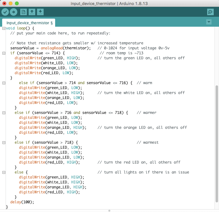
In essence my loop function reads the sensor and turns on one LED if the temperature reaches a certain point. The way thermistors work is that their resistance gets smaller as the temperature increases. The sensor gives an analog value from 0 to 1024, depending on the voltage through the component (0v to VCC). So, this means that if I heat up the sensor, resistance and voltage will decrease and the sensor reading should go toward zero too.
I tried using a decreasing sensorValue for the "if else" statements in my code, but this didn't work. I changed the values to be increasing, and I realized that I had it flipped. Since I used a pull-up resistor, the default voltage was VCC, so the sensorValue of 0 is actually 5 volts and when the sensorValue increases, the voltage (and resistance) decreases.
Here is the final version of the code for the loop I ended up using.
There were a few instances beforehand where I got the LED's to turn on with the input fron the thermistor, but the lights kept flickering. I thought this was an issue with the sensor reading, but I had actually just forgot to put in a delay. This clip shows what the lights looked like with the issue.
After I added the delay, the light shifts stabilized. Here my video shows the LED's changing when the temperature increases. The board started at about room temperature and I warmed it up using a soldering heat gun. (I know this was risky, but I kept the heat low enough to not melt the solder!)
This next video is a bit longer, but it shows me testing my board somewhere in the middle of the process where I was tweaking the sensorValues in the "if" statement conditions, and the length of the delay. Since I have the code set up so that green is room temperature and red is the warmest, the video also shows how the LED's light up in the reverse direction when the board is cooling down.
Resources
- Datasheets: ATtiny402 | Thermistor NTC
- Pull-up and pull-down resistors
- Digital Pins | Analog Input Pins
- Arduino and Thermistors | Arduino example
- Potentiometer vs Rotary encoder
Design Files
(includes schematic and PCB layouts for ATtiny1616)
Updated: March 14, 2021