NETWORKING AND COMMUNICATIONS
This week I learned how to make microcontrollers send data back and forth.
The assignment:
- Send a message between two projects (in groups)
- Make and compare test casts with each of them (in groups)
- Design, build, and connect wired or wireless node(s) with network or bus addresses
Group Work
During our Lab time we worked on getting two of our boards to talk to each other. Two teams wrote the codes for the sending and receiving board separately, and then we combined them.
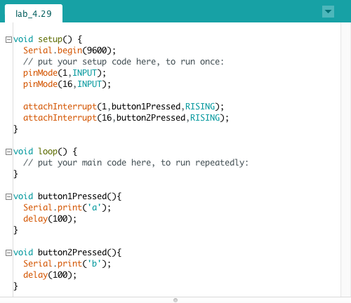
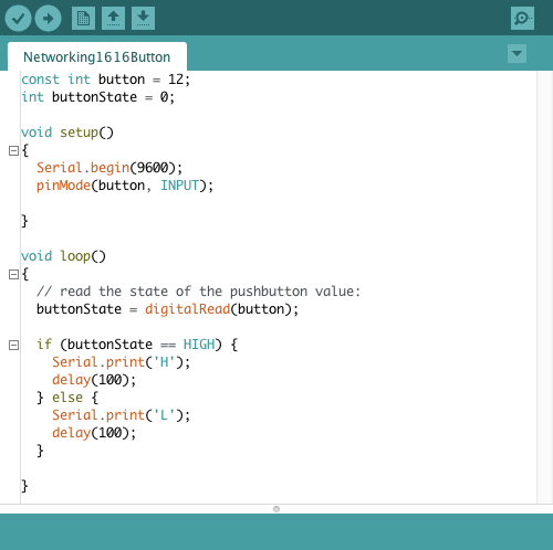
My group wrote this code for the sending device. It sends a different letter character based on which button on the board is pressed. After checking this in the serial monitor it seemed to work.
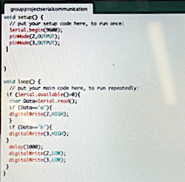
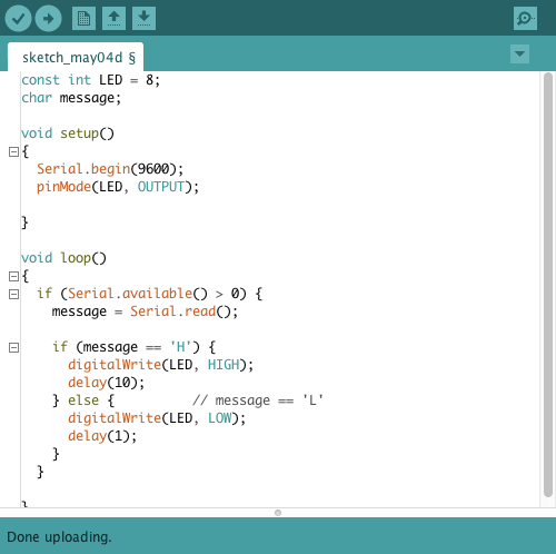
And this was the receiving code. This turned on a red or green LED based on which character was sent.
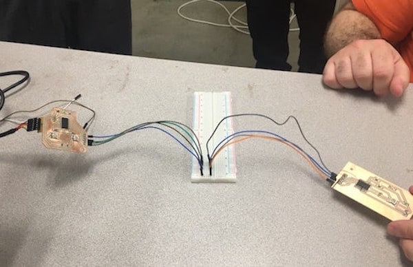
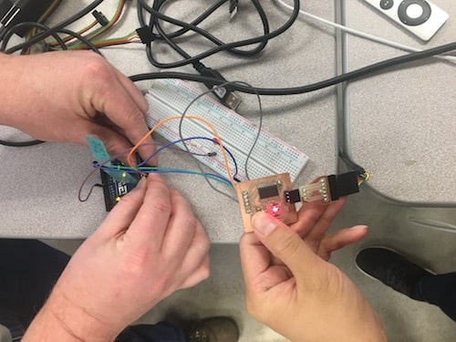
Once we had our codes working on our own computers, we wired them together. The button board is on the left and the LED board is on the right. We connected GND -> GND, VCC -> VCC, TX -> RX, and RX -> TX. Also, we powered it from a computer on the sending board.
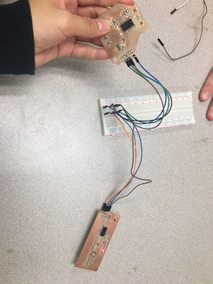
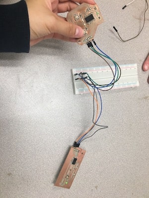
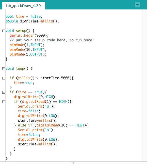
We also made a quick draw game where two players try to press a button first, and the winner's LED is shown on the other board.
Networking
For the individual assignment, I planned on using the Board that I made in Week 7, but I had some trouble because I discovered that my chip was dead. There were UPDI initialization errors when I went to upload the code.
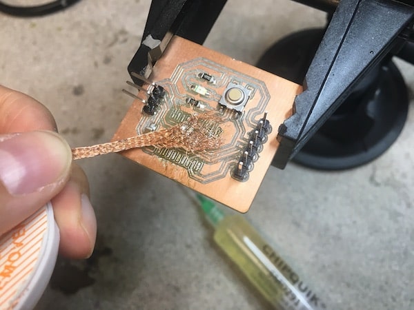
Our Lab was running low on the ATtiny1616s that I designed my board for, but after soldering and testing like 4 different chips I miraculously found one that worked! Before stuffing the board with that new chip, I cleaned up some of the traces using an Exacto blade, de-soldering braid, and flux paste. Then, I double checked for continuity to see that there weren't any unexpected connections.
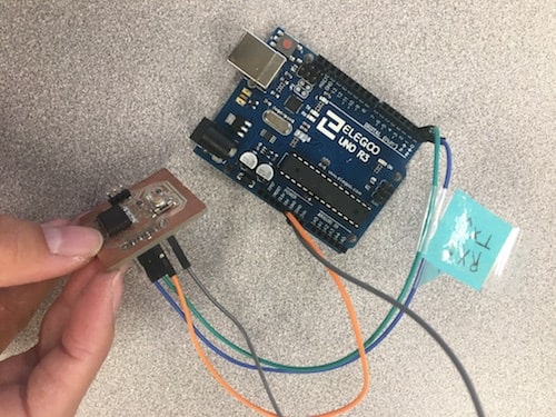
This shows how I wired the boards. I connected the TX and RX on my PCB to pins 0 and 1 on the Arduino. Here, I am using serial communication in which data gets transmitted over a serial bus, between a source and destination, one bit at a time. This is one of the most common types of networking methods, found in USBs. The serial bus uses two wires for communication, one for transmitting (TX) data and one for receiving (RX) data. The other orange and gray wires you see are power and ground.
I had some issues with the code. First the LED on the wrong board turned on when I pressed the button.
There were a few things that needed fixing. First, I disconnected the board from the computer when running the code, that way there was only one serial connection. There was an issue with the placement of the delays, and them being too long, so I fixed that too. Also, I made sure to disconnect the boards from eachother before updating the code every time.
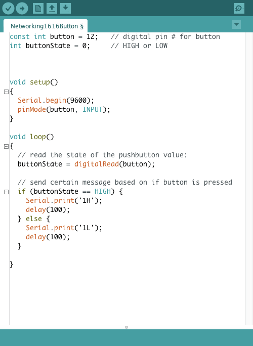
This time it worked! The first image below is the code for the sending device, my PCB, and the second image is the receiving code for the Arduino.
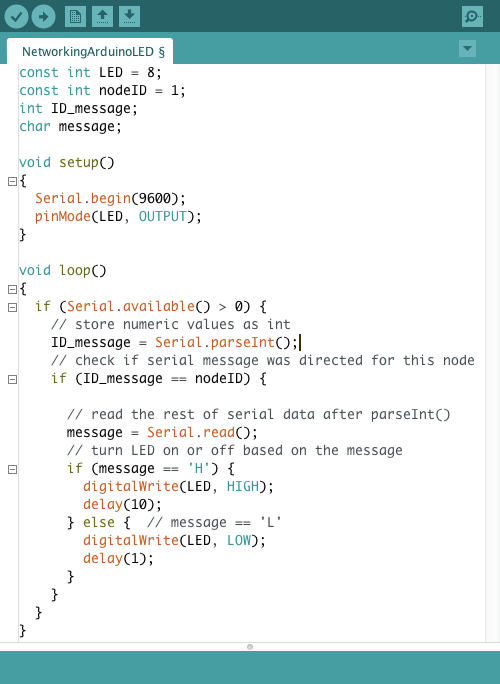
After this, I worked on addressing. I gave my receiving board a node ID and edited the code so that the receiving board would only respond to messages meant for it. Here are the updated codes.
This is the video of the serial bus communication.
Resources
- ATtiny1616 Datasheet
- Arduino pinout diagram
- Serial Communication
- Other Networking devices
- Serial.read() vs Serial.parseInt()
- Fab Academy: Mohamed Ayoub Aissaoui | Muhammed Athif Kurukkoli
Design Files
Updated: May 15th, 2021