Assignment 13
Networking and Communications
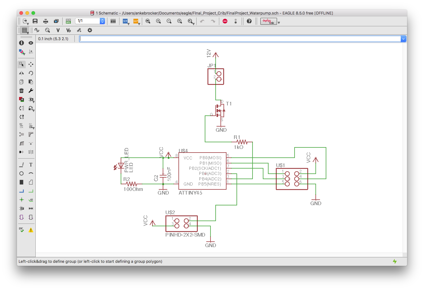
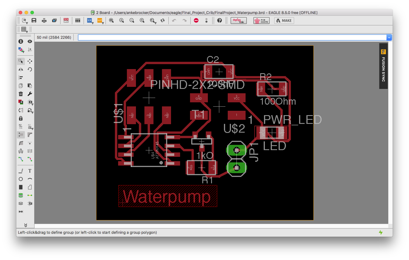
As for my final project I want to have two boards that can communicate I wanted to get this working this week already: Therefore, I built a board that controls the waterpump for the watering place of my final project. I designed the board using eagle. Underneath you can see the schematic and the board file of this board.
Schematic and Board
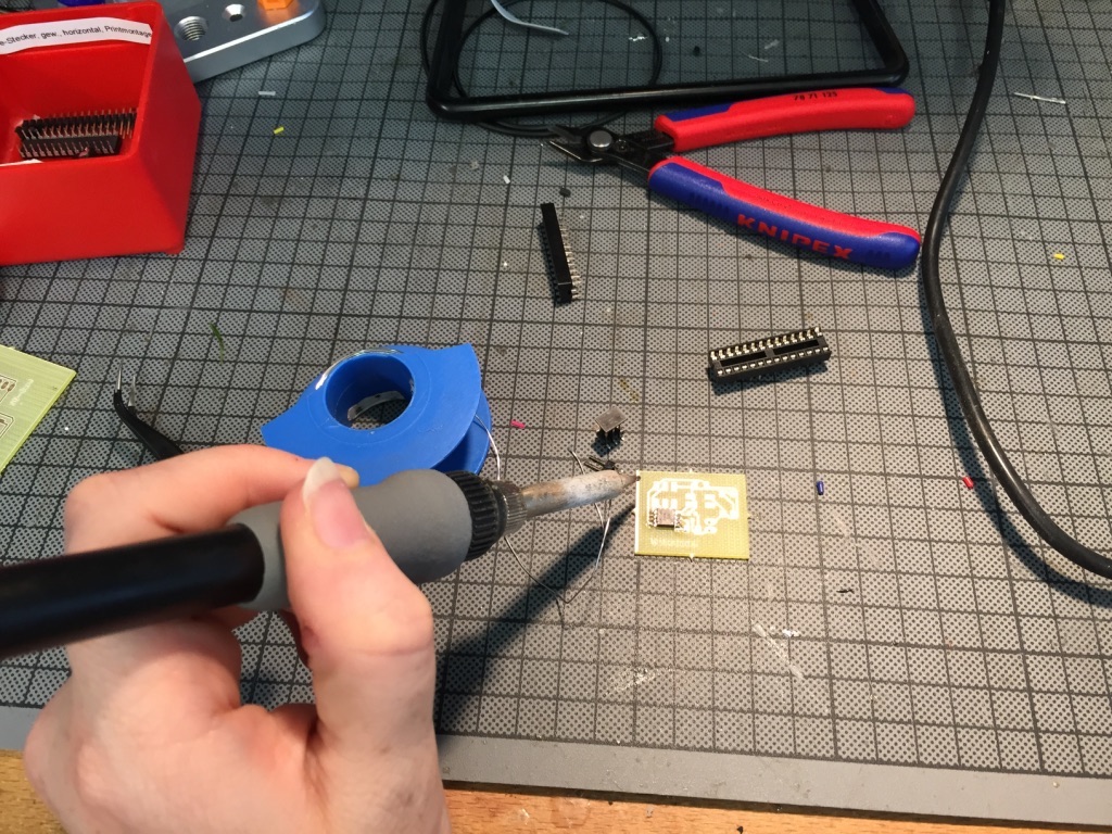
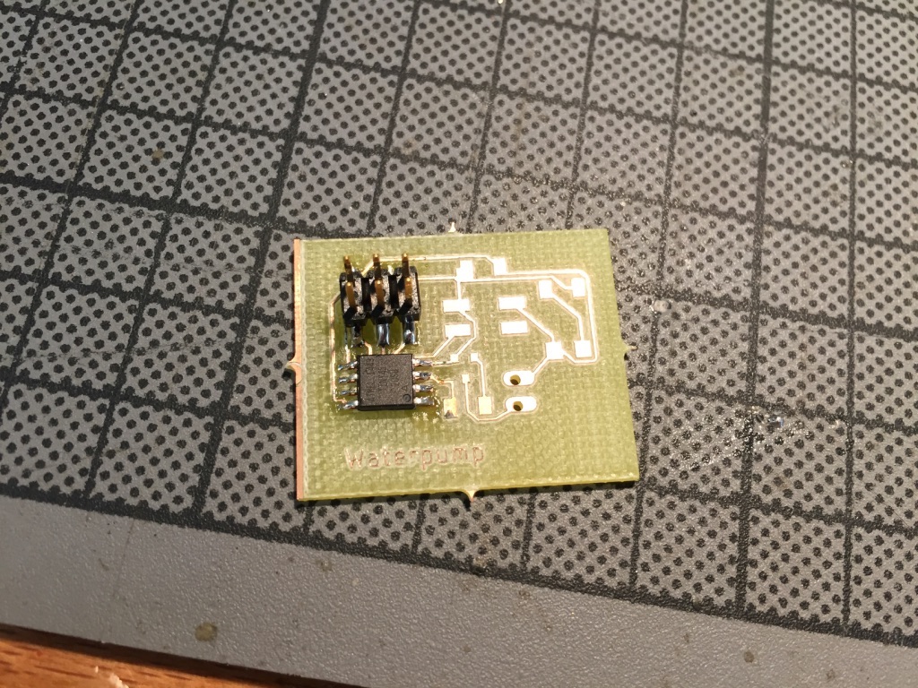
Soldering
All components used on the Waterpump board after it was milled:1. 1 x Attiny 45
2. 1 x 100nF SMD Capacitor
3. 2 x 1kΩ SMD Resistor
4. 1 x 1000Ω SMD Resistor
5. 1 x green SMD LED
6. 2 x 3 Pinheader SMD
7. 2 x 2 Pinheader SMD
8. 1 x 2 Pinheader
9. 1 x Mosfet SOT-23
Networking Protocols to Communicate
Pulse Width Modulation
The definition of Pulse Width Modulation (PWM) is: modulating the
width of the pulse. To best understand what PWM is, let us first see some basic terminologies.
Pulse-width modulation (PWM) is used for controlling the amplitude of digital signals in order to control devices and applications requiring power or electricity.
It controls the amount of power that is given to a device by cycling the on-and-off phases
of a digital signal quickly and varying the width of
the "on" phase or duty cycle. To the device, this would appear as a steady power input with an average voltage value, which is the result of the percentage of the on
time.
A very powerful benefit of PWM is that power loss is very minimal.
Compared to regulating power levels using an analog potentiometer to limit the power output,
PWM actually turns off the power output rather than limits it. Usage can be e.g. controlling DC motors or heating elements.
I2C
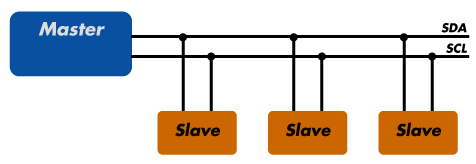
The Attiny45 also includes two pins to be able to communicate via I2C protocol. These pins are called SCL (serial clock) & SDA (serial data). I2C always needs one processor to be the master and at least one
other processor has to be the slave. But multiple slaves are also possible.
With I2C, you can connect multiple slaves to a single master and you can have multiple masters controlling single,
or multiple slaves. Since only two wires are required, I2C is well suited for boards with many devices connected on the bus.
Therefore, I decided to use a serial connection and a bluetooth module to communicate between two processors.
Programming Communication
Bluetooth-Serial Connection
I wrote two programs, one in the Arduino IDE for the microcontroller and one App in Processing to setup a bluetooth-serial communication between two processors. For the bluetooth communication I used an HC-05 module (Datasheet) for the bluetooth communication. To test if the overall setup of the bluetooth serial connection works I used the Arduino Uno as the board first. Afterwards, I programmed my self-built board.
Arduino Uno Test
Arduino IDE
       #include
                    // the setup function runs once when you press reset or power the board
                    void setup() {

                      Serial.begin(9600); // 9600 baudrate of the HC-05 Bluetooth module
                      pinMode(4, OUTPUT);


                    }

                    void On(){
                     digitalWrite(4, HIGH);
                    }

                    void Off(){
                     digitalWrite(4, LOW);
                     // delay(15);
                    }

                    // the loop function runs over and over again forever
                    void loop() {


                    while(Serial.available()) {
                      int command = Serial.read();

                      Serial.print(command);

                      if (command == 49){
                          On();
                      }
                      else {
                        if(command == 48) {
                            Off();
                        }
                      }

                      delay(15);
                    }
                    }
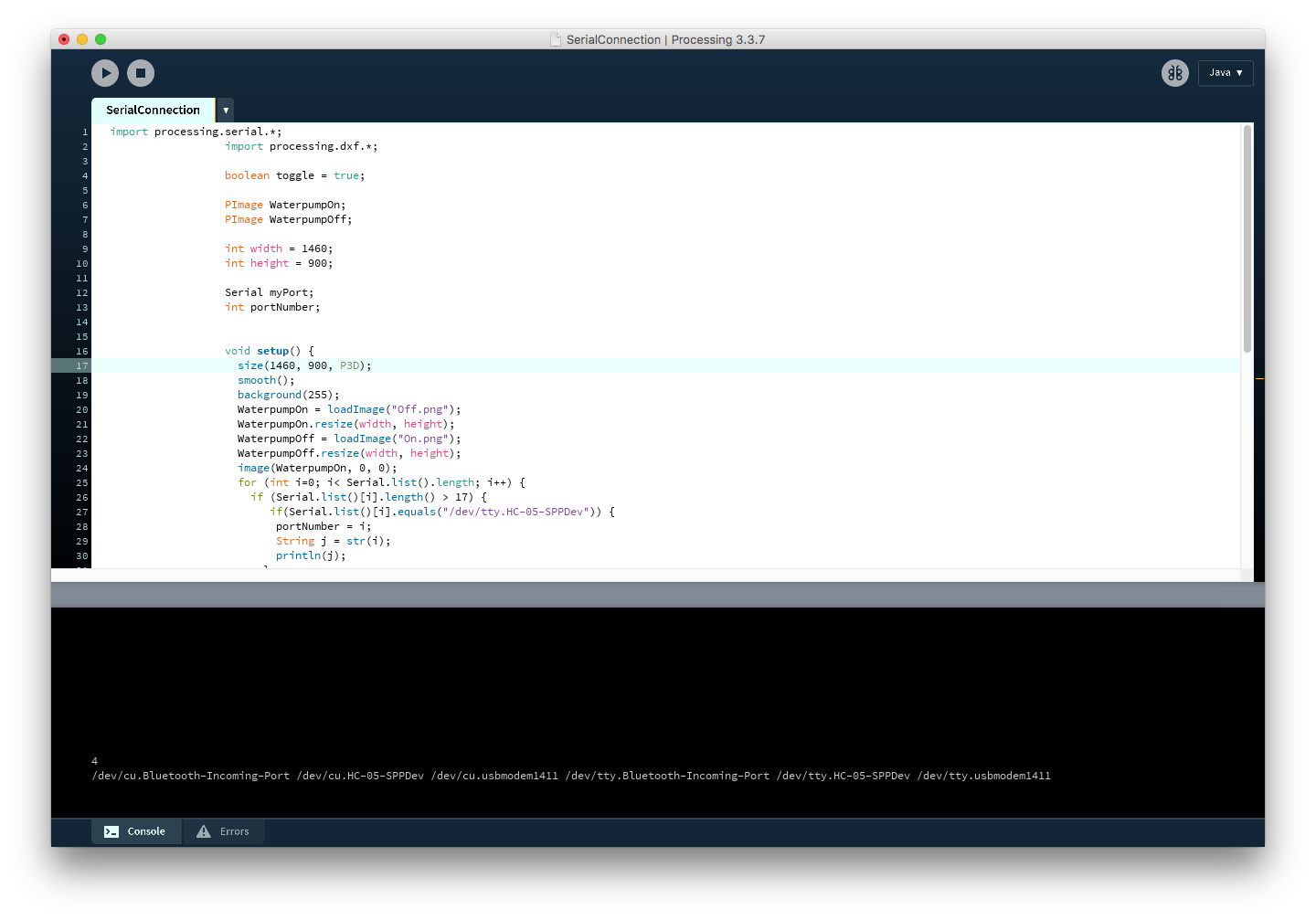
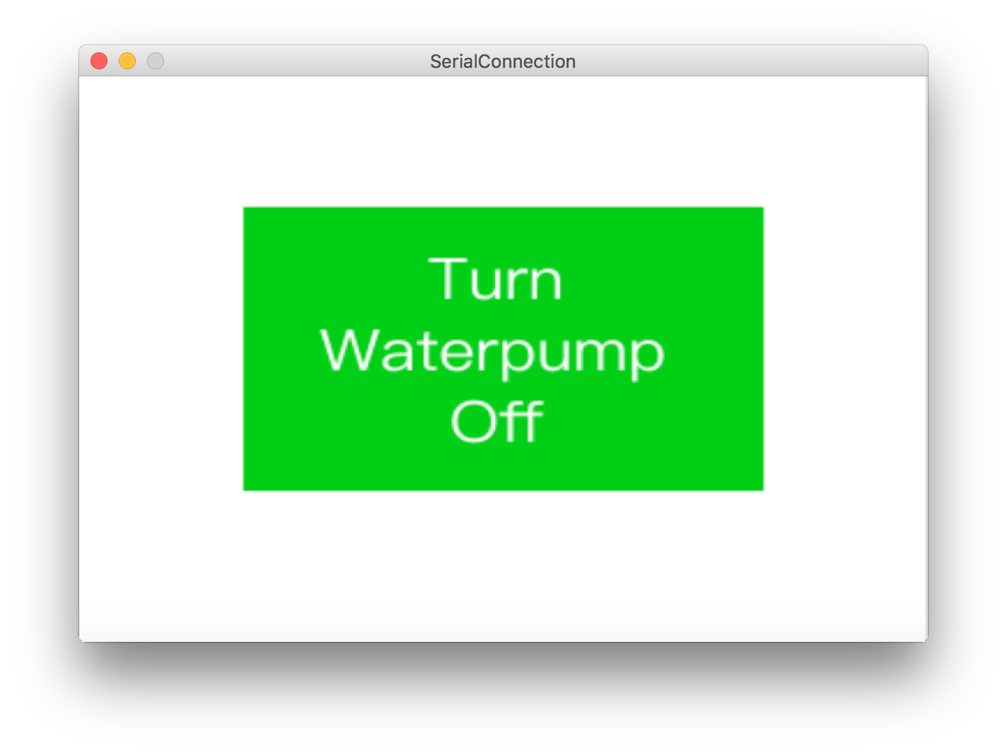
Processing App
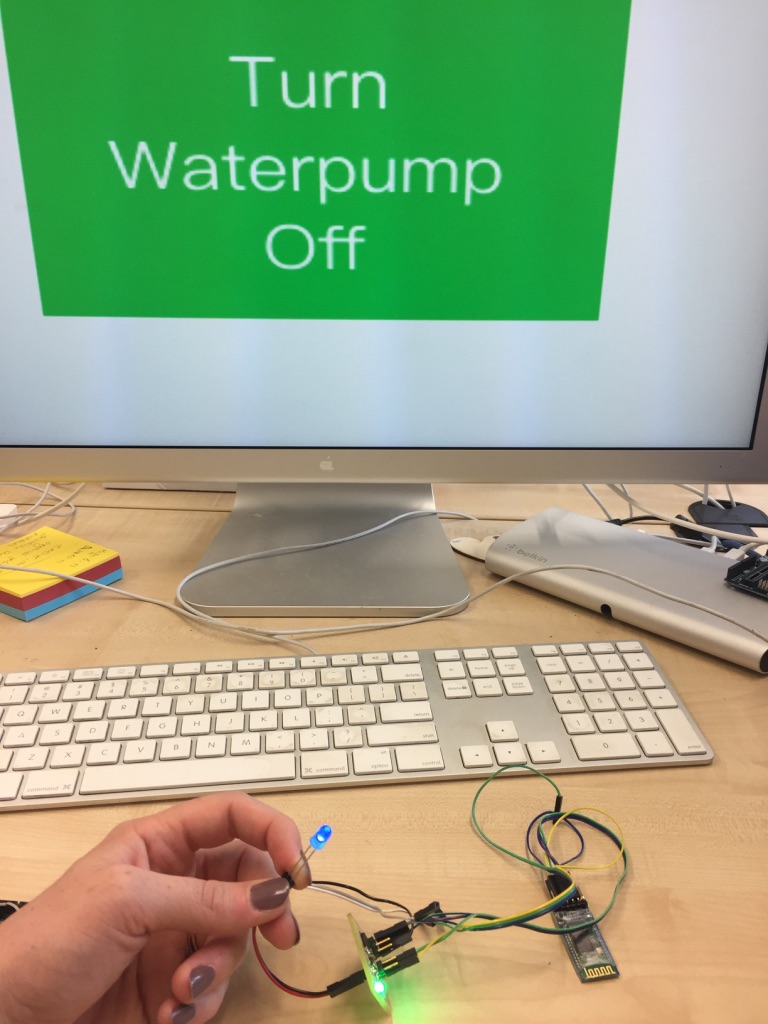
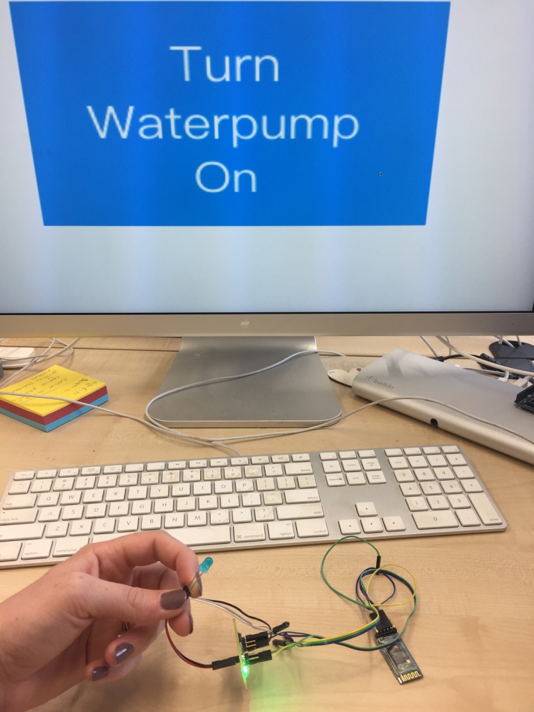
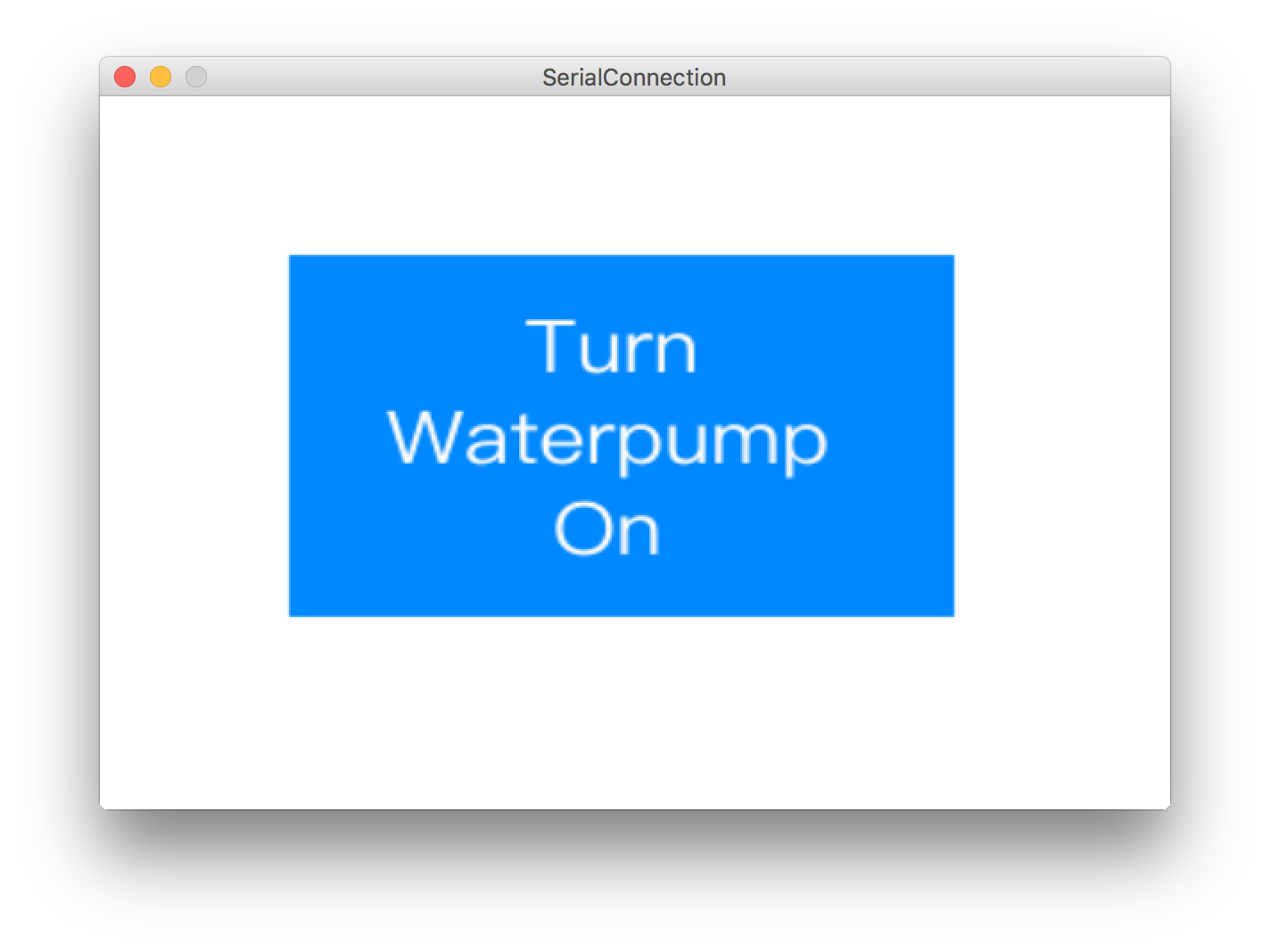
The processing App was used to send controls to the bluetooth module which controls if the waterpump is turned on or off. The interface of the app basically just shows a window with a button underneath to change the state of the waterpump and has two states (Waterpump on/off). The processing App also sets up the bluetooth communication with the HC-05 module, i.e. it chooses the HC-05 module in the connected bluetooth devices list of the Mac to send data to it.
                    import processing.serial.*;
                    import processing.dxf.*;

                    boolean toggle = true;

                    PImage WaterpumpOn;
                    PImage WaterpumpOff;

                    int width = 1460;
                    int height = 900;

                    Serial myPort;
                    int portNumber;


                    void setup() {
                      size(1460, 900, P3D);
                      smooth();
                      background(255);
                      WaterpumpOn = loadImage("Off.png");
                      WaterpumpOn.resize(width, height);
                      WaterpumpOff = loadImage("On.png");
                      WaterpumpOff.resize(width, height);
                      image(WaterpumpOn, 0, 0);
                      for (int i=0; i< Serial.list().length; i++) {
                        if (Serial.list()[i].length() > 17) {
                           if(Serial.list()[i].equals("/dev/tty.HC-05-SPPDev")) {
                            portNumber = i;
                            String j = str(i);
                            println(j);
                          }
                        }
                      }
                      println(Serial.list());

                      String portName = Serial.list()[portNumber];
                      myPort = new Serial(this, portName, 9600);

                      myPort.write("0");
                    }

                    void draw() {
                    }


                    void mousePressed() {
                      blendMode(REPLACE);
                      background(0);
                      blendMode(ADD);
                      if (toggle) {
                        myPort.write('0');
                        image(WaterpumpOn, 0, 0);
                      } else {
                        myPort.write('1');
                        image(WaterpumpOff, 0, 0);
                      }
                      toggle = !toggle;
                    }
How to set up the connection:
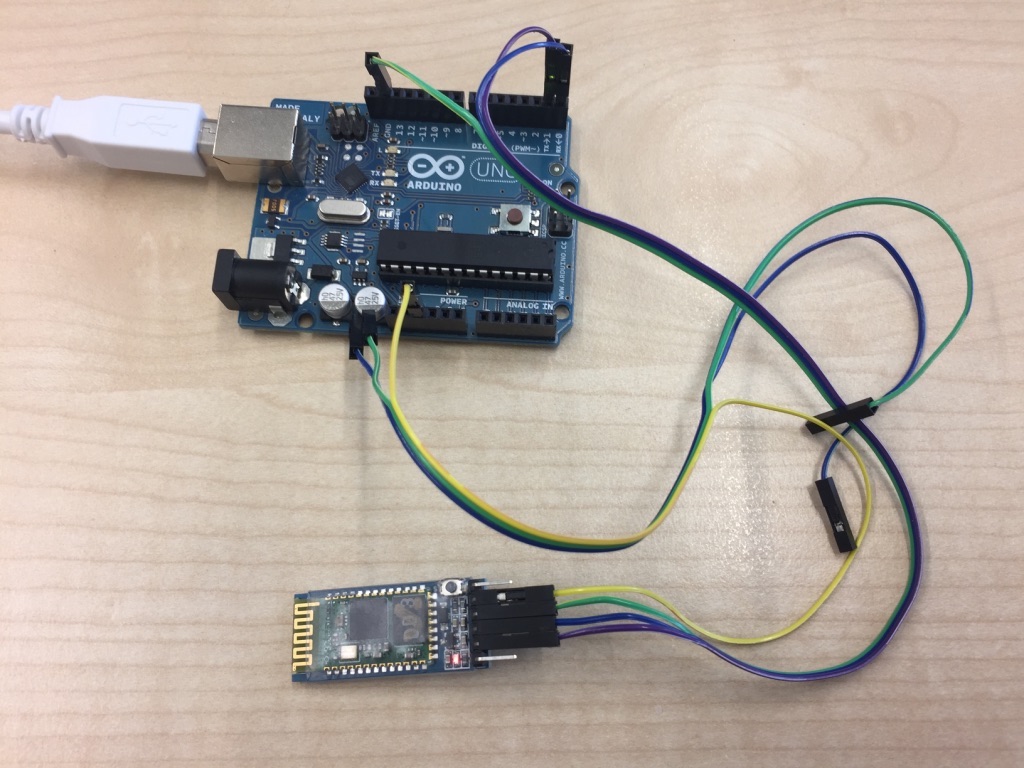
1. Uploaded the Arduino IDE program onto the Arduino.2. Connected the Arduino Uno and the bluetooth module the following way:
- GND - GND
- VCC - VCC
- RX (Arduino) - TX (Bluetooth module)
- RX (Bluetooth module) - TX (Arduino)
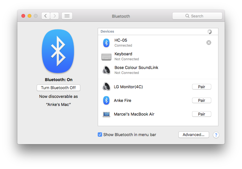
4. Connected my Mac with the HC-05 bluetooth module.
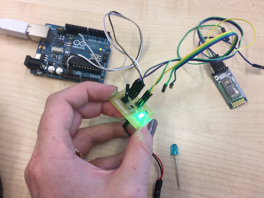
Using Self-Built Board
Arduino IDE
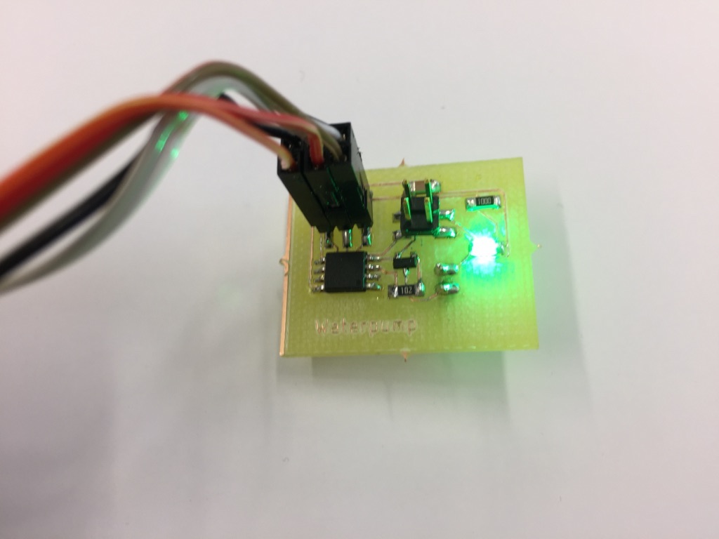
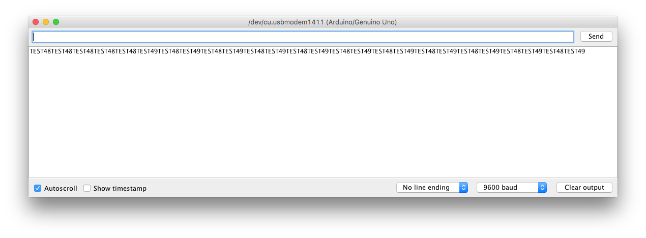
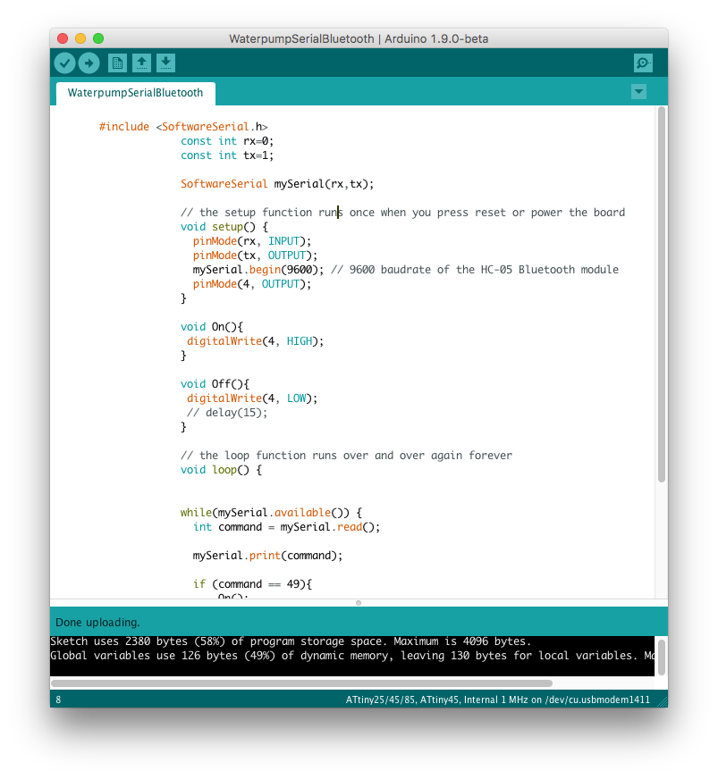
The Arduino IDE program sets up the serial communication between my self-built board and my serial port of the Mac. In the serial Monitor of the Arduino IDE I could see the commands that were received by the bluetooth module from the Mac and then used on the board to control the waterpump in my later project and in this scenario the LED.
                     #include
                    const int rx=0;
                    const int tx=1;

                    SoftwareSerial mySerial(rx,tx);

                    // the setup function runs once when you press reset or power the board
                    void setup() {
                      pinMode(rx, INPUT);
                      pinMode(tx, OUTPUT);
                      mySerial.begin(9600); // 9600 baudrate of the HC-05 Bluetooth module
                      pinMode(4, OUTPUT);
                    }

                    void On(){
                     digitalWrite(4, HIGH);
                    }

                    void Off(){
                     digitalWrite(4, LOW);
                     // delay(15);
                    }

                    // the loop function runs over and over again forever
                    void loop() {


                    while(mySerial.available()) {
                      int command = mySerial.read();

                      mySerial.print(command);

                      if (command == 49){
                          On();
                      }
                      else {
                        if(command == 48) {
                            Off();
                        }
                      }

                      delay(15);
                    }
                    }
Processing App
The Processing App is the same as the one described above.How to set up the connection:
1. Uploaded the Arduino IDE program onto the Attiny45 board using the Arduino as an ISP.
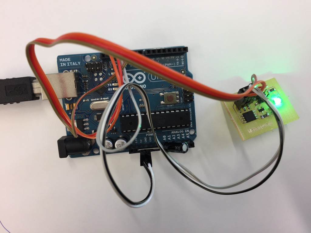
2. Connected the Attiny45 and the bluetooth module the following way:
- GND - GND
- VCC - VCC
- RX (Attiny) - TX (Bluetooth module)
- RX (Bluetooth module) - TX (Attiny)
4. Connected my Mac with the HC-05 bluetooth module.