Assignment 7
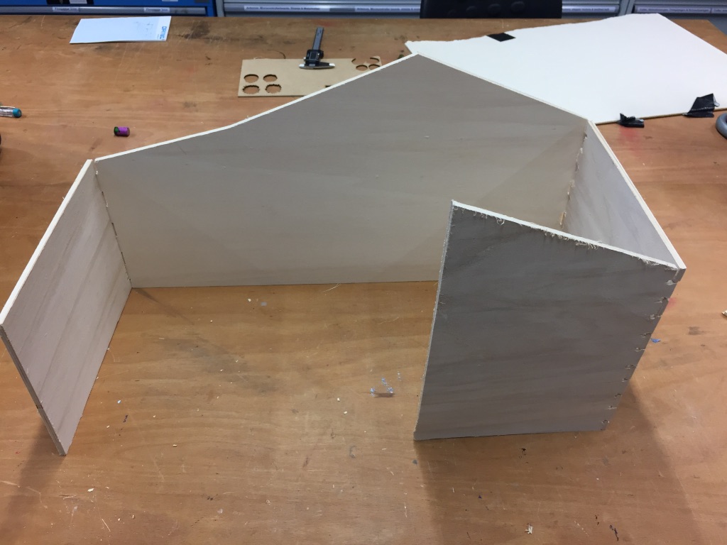
Make something BIG
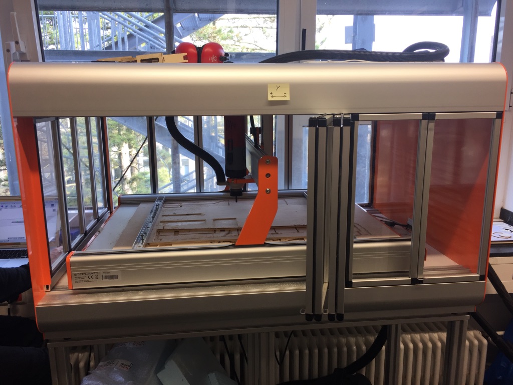
CNC machine: Stepcraft
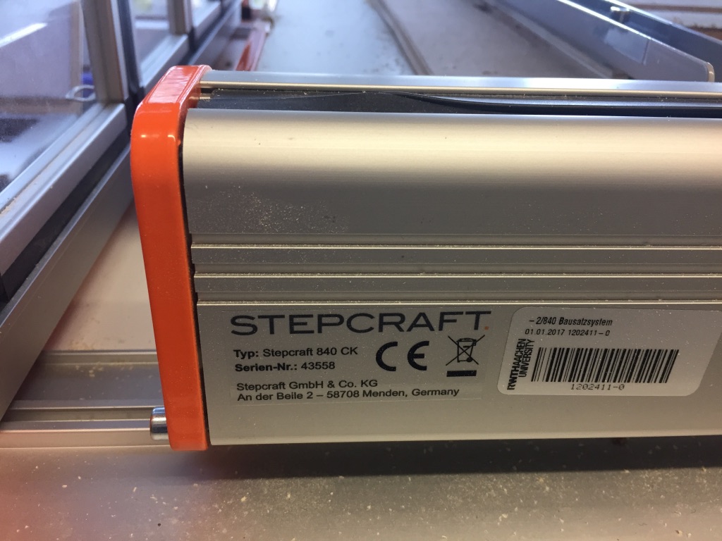
In our lab we have a Stepcraft 840 CK. As this machine is relatively new it took me longer than for the other machines in the lab to understand how to make it work. At the moment we mostly mill wood and foam with the CNC-machine but we plan to mill other materials in the future as well. We hope to have this finished during the next weeks.
Design with Fusion360
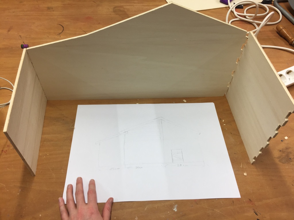
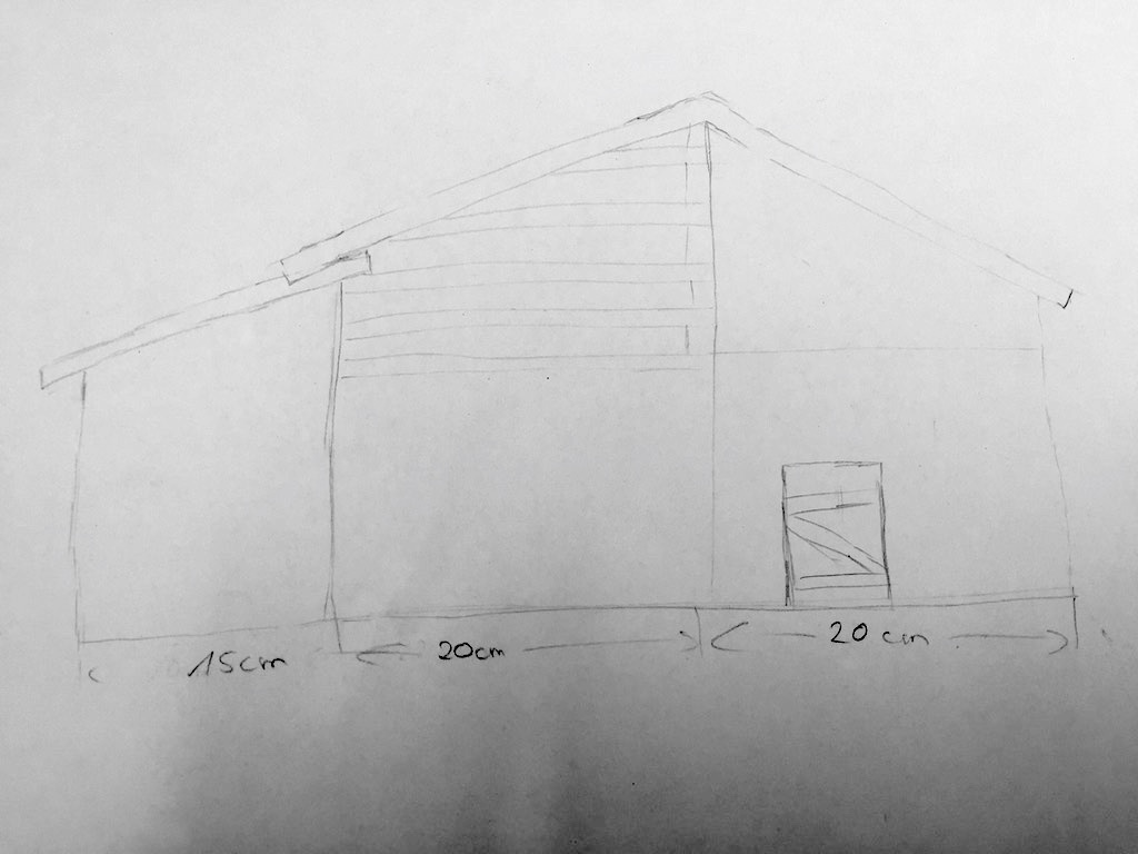
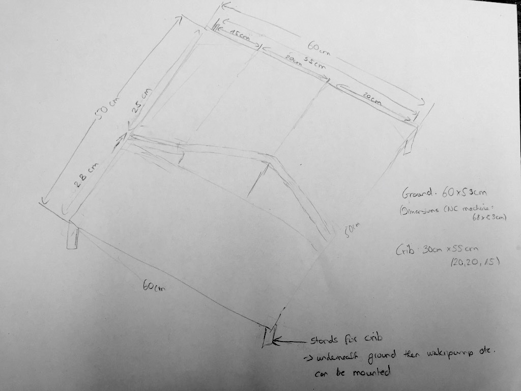
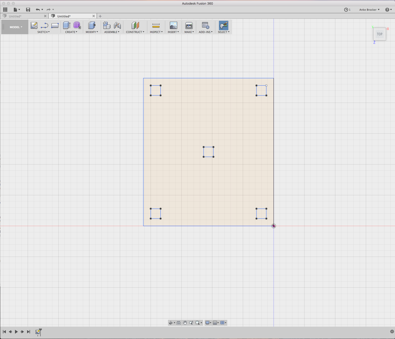
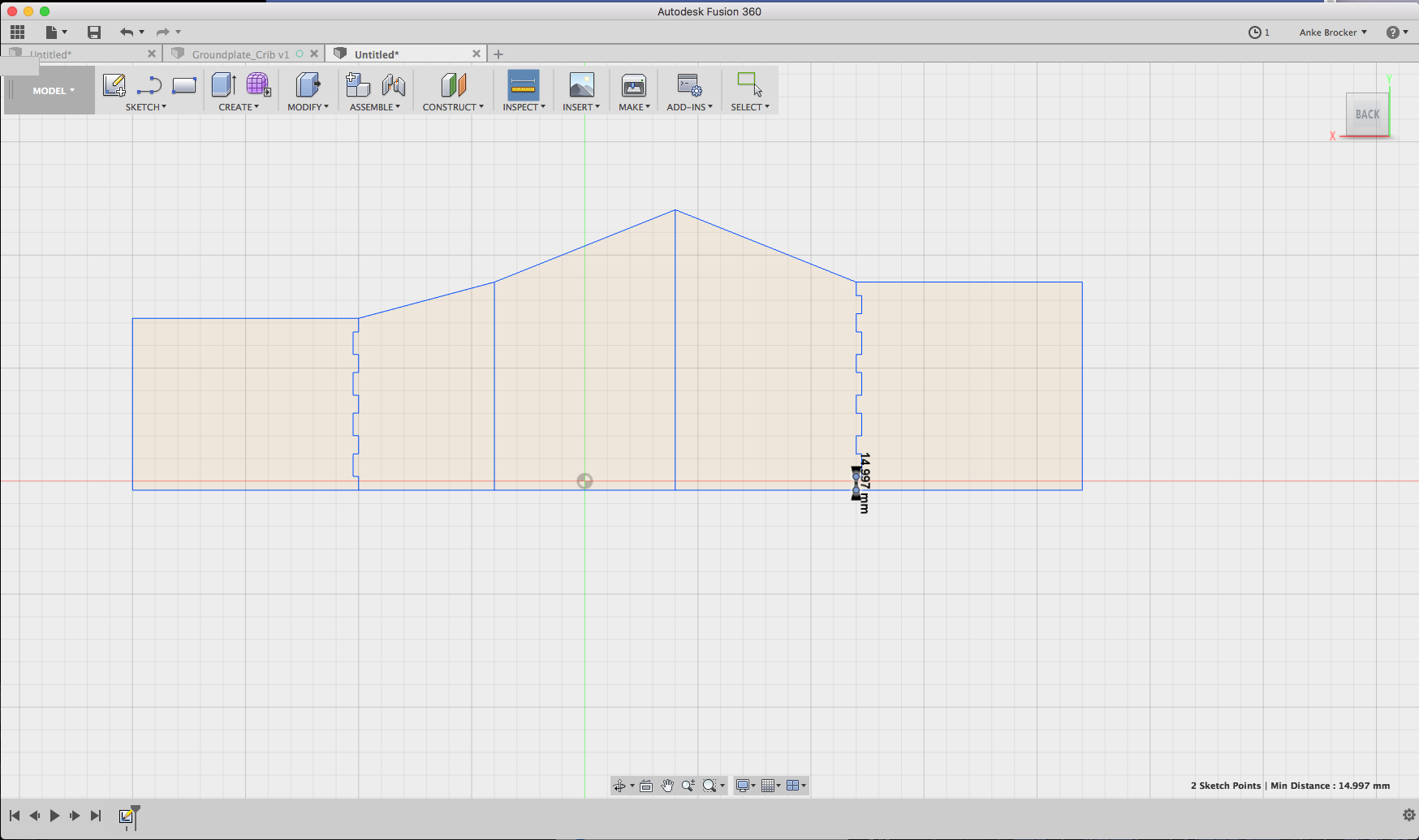
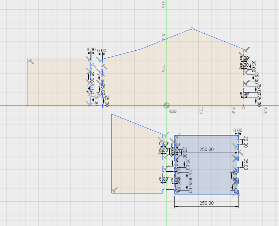
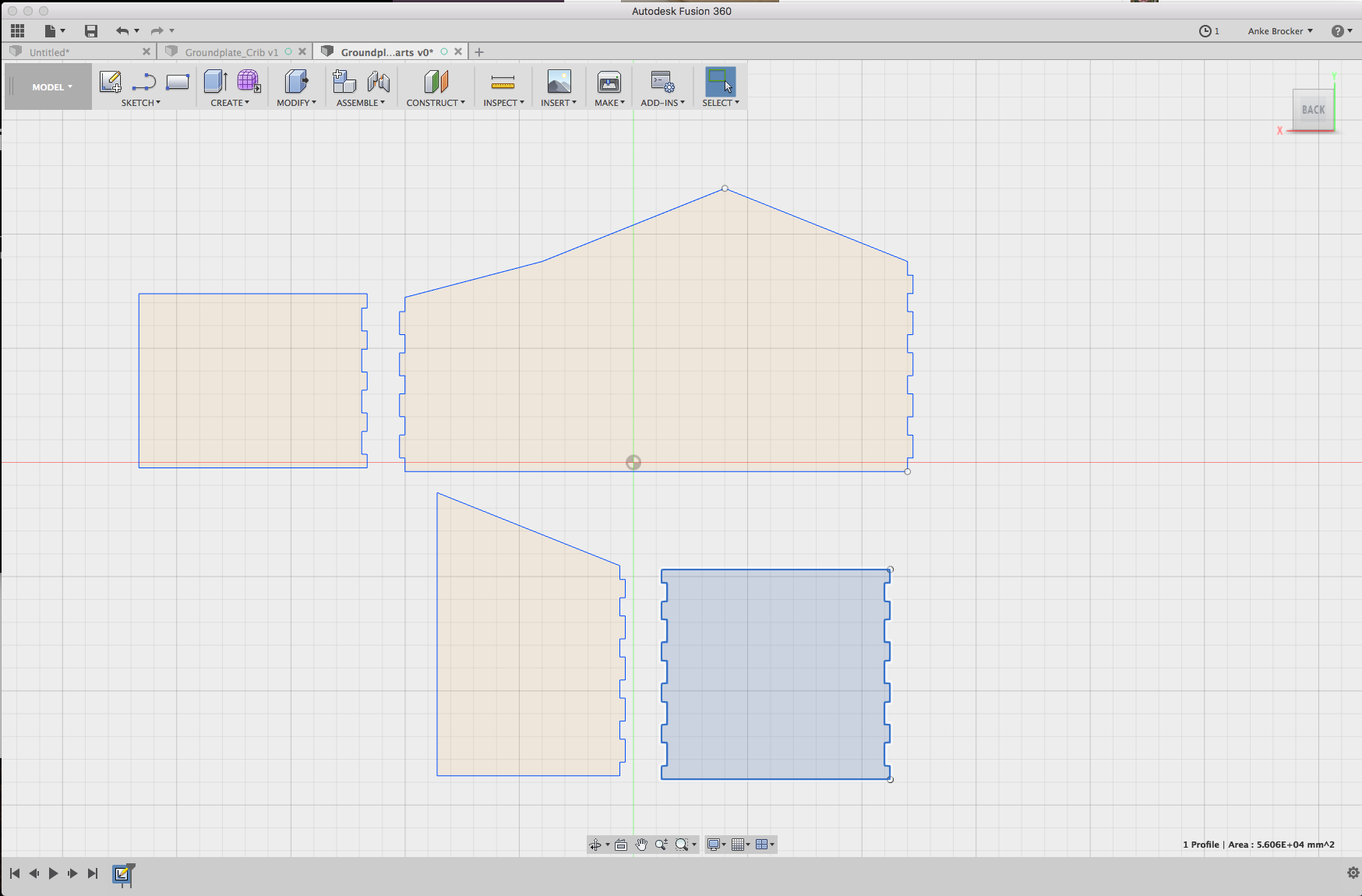
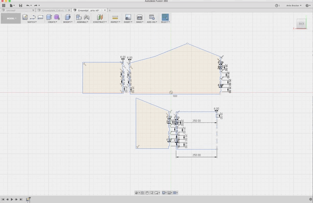
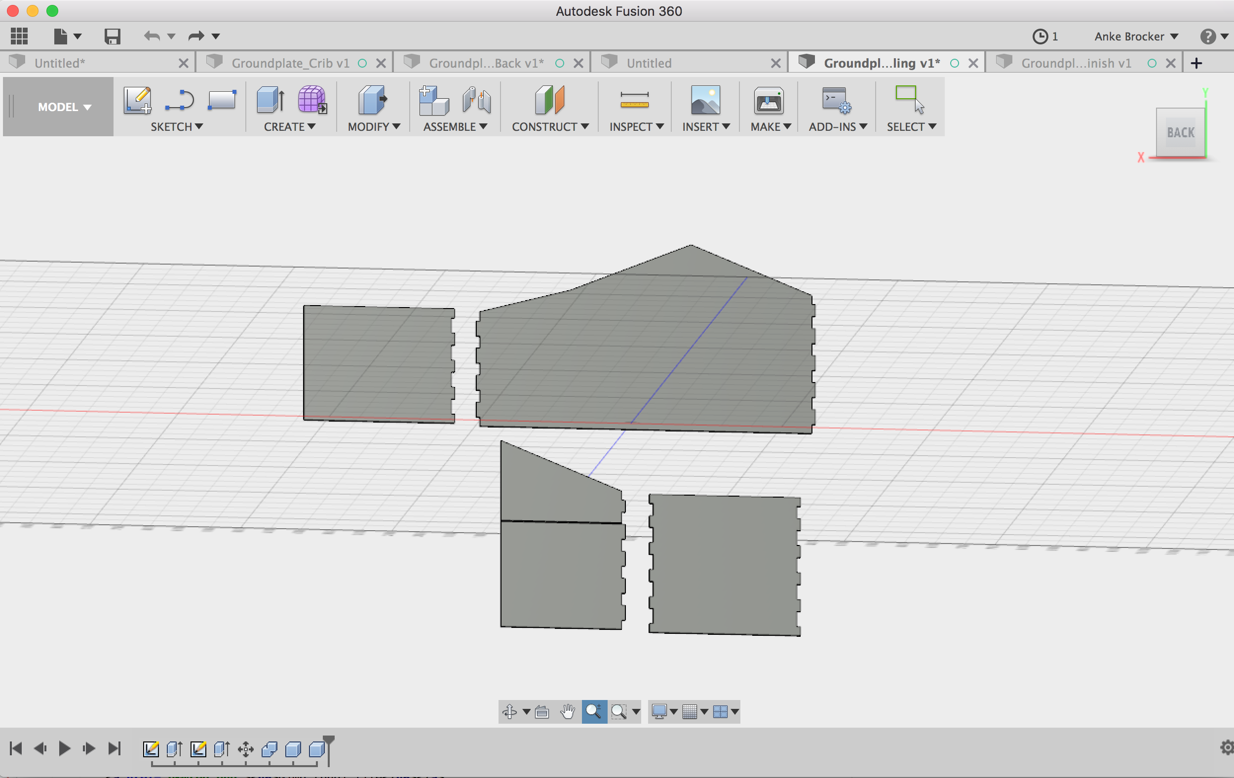
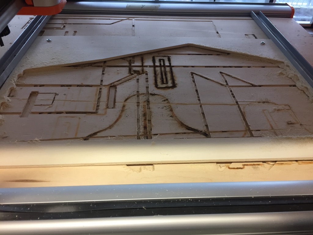
I did design the house for my crib with Fusion360. Mainly because we use Fusion360 to generate the needed gcode for the stepcraft software to mill. I have not worked with Fusion360 before, thats why I took some time to just play around with the tool. I also used this tutorial page to get a deeper understanding how to design with the software. After around an hour I felt started working on my house design.
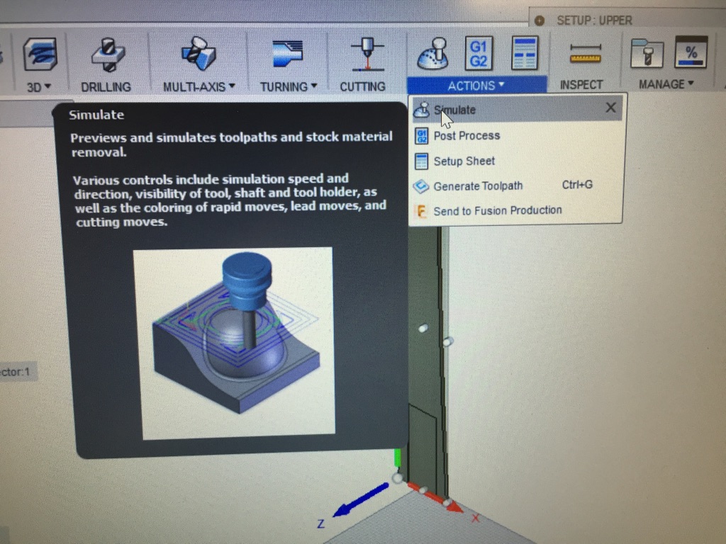
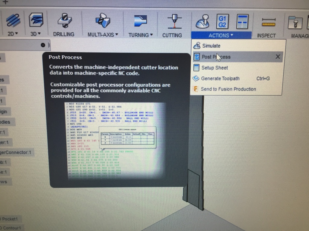
CAM processor of Fusion360
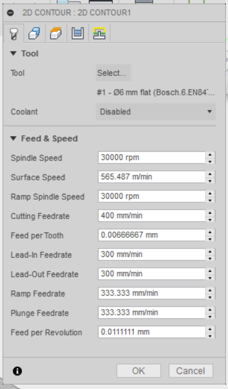
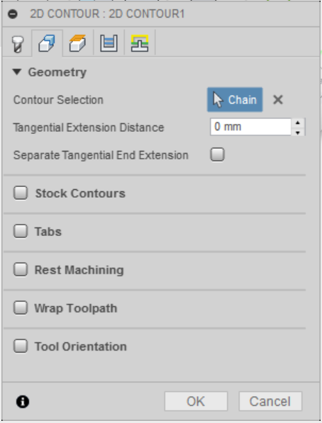
After a few cycles I was able to use the Cam processor myself. At first it did look quite complicated but in the end only around 10 clicks are necessary to prepare the object to be processed into gcode. One thing that is really important to take care of. When designing your objects in Fusion make sure that the Z-axis is pointing into the top direction. Usually this is the default but somehow in my design the Y-axis was pointing to the top. This complicated the CAM process a lot because the coordinate system was wrong.To prepare the gcode for the milling follow these steps:
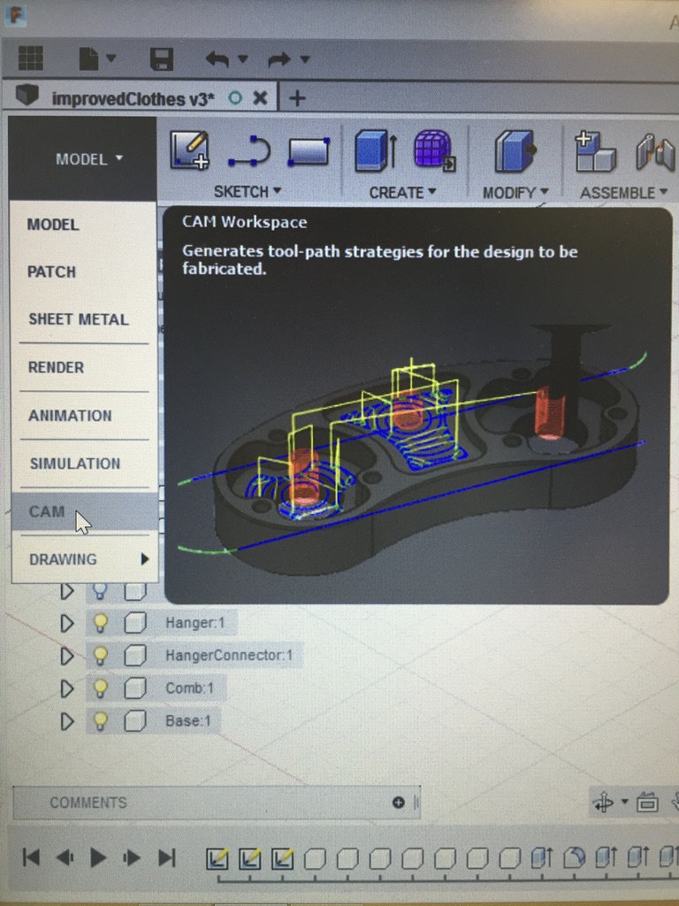
1. After designing your model you need to prepare the object to be generated into gcode for the milling machine. First of all, you need to change from the 'Model' view into the 'CAM' view
(see picture a.). Now your tap should look like this:
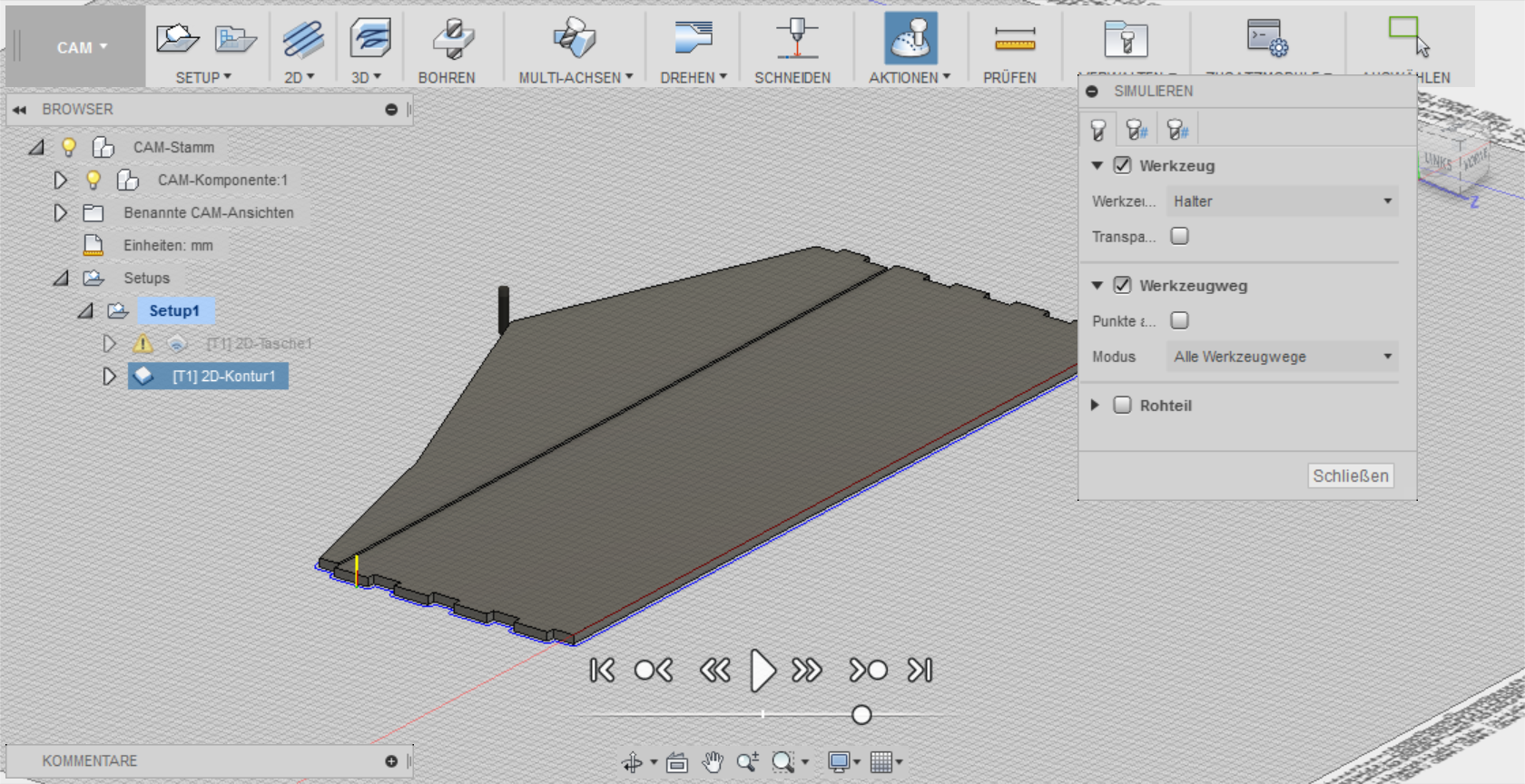
2. Now you need to define your setup, i.e. define what you want to mill. I used the 2D options that Fusion provides.
Click on the this button  to choose between the 2D options. I chose a '2D-Contour'.
3. After your have chosen an option what you want to drill you need to set some more attributes. Therefore, double-click on 'Setup' in the tree
on the left of the Fusion interface 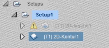 .
.
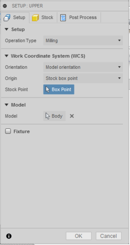
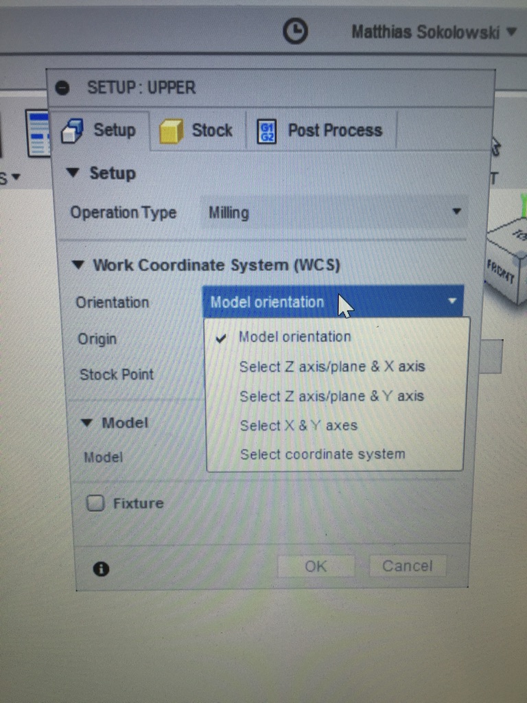
5. After you have defined the axes you need to set your attributes for the '2D-Contour'.
Therefore, double-click on '2D-Contour' in the tree
on the left of the Fusion interface .
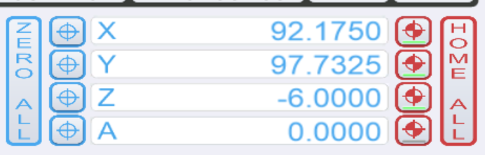
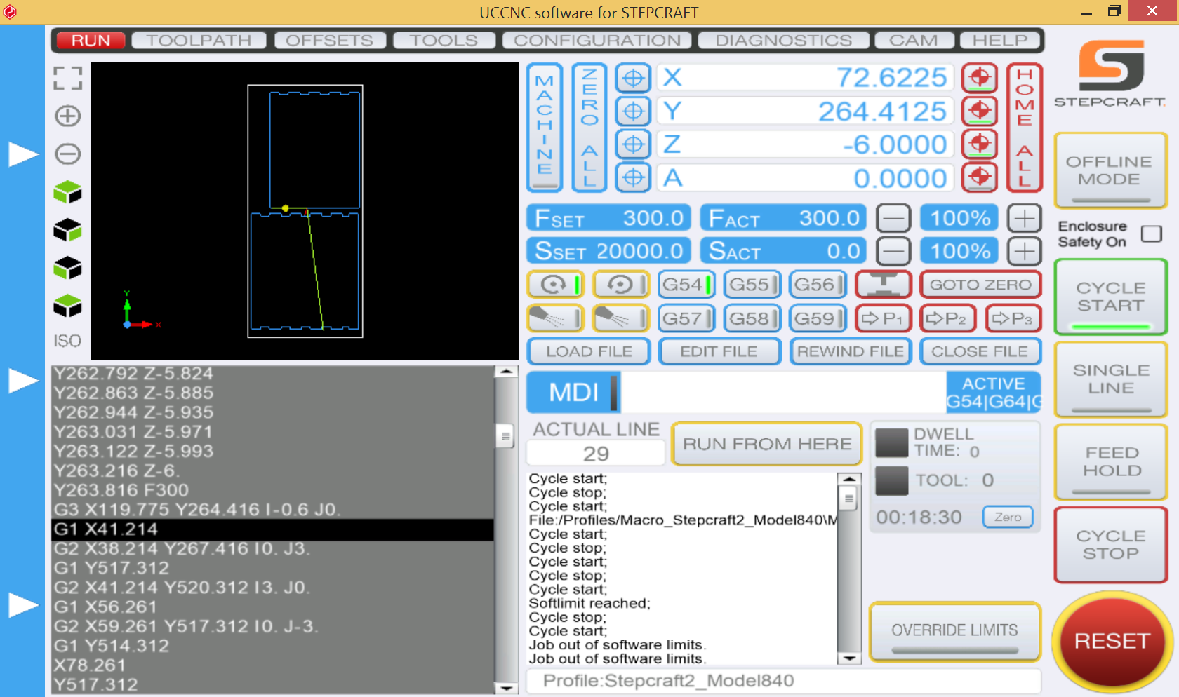
UCCNC software Stepcraft
For the stepcraft machine we have a special software to move to drilling head and start milling. The interface of the software when opening it you can see on the picture underneath. As you can see that interface is quite unclean and could need some redesign in terms of design laws.

1. Load the file you saved on your computer before into the software by clicking on the button 'Load file'
2. Start moving your drill head with the arrow keys on your keyboard to a position where the zero coordinate of your model is. Then click the button 'Zero All'
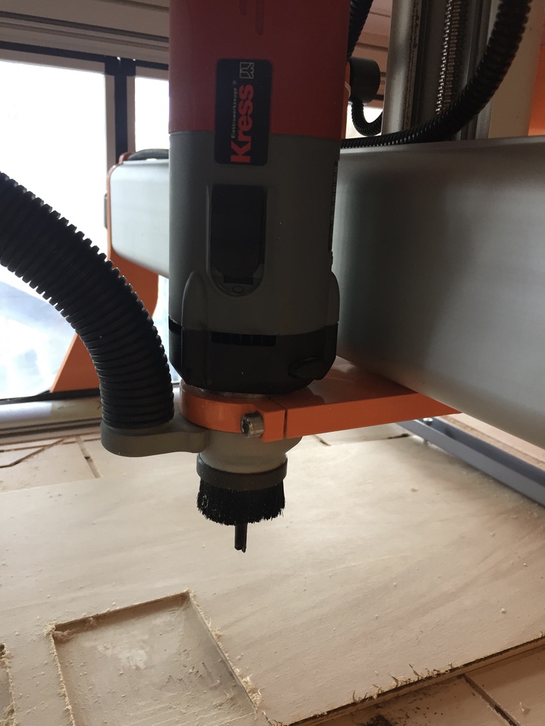
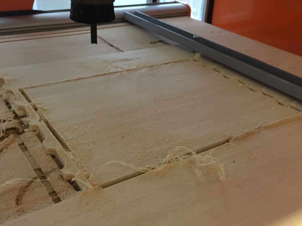
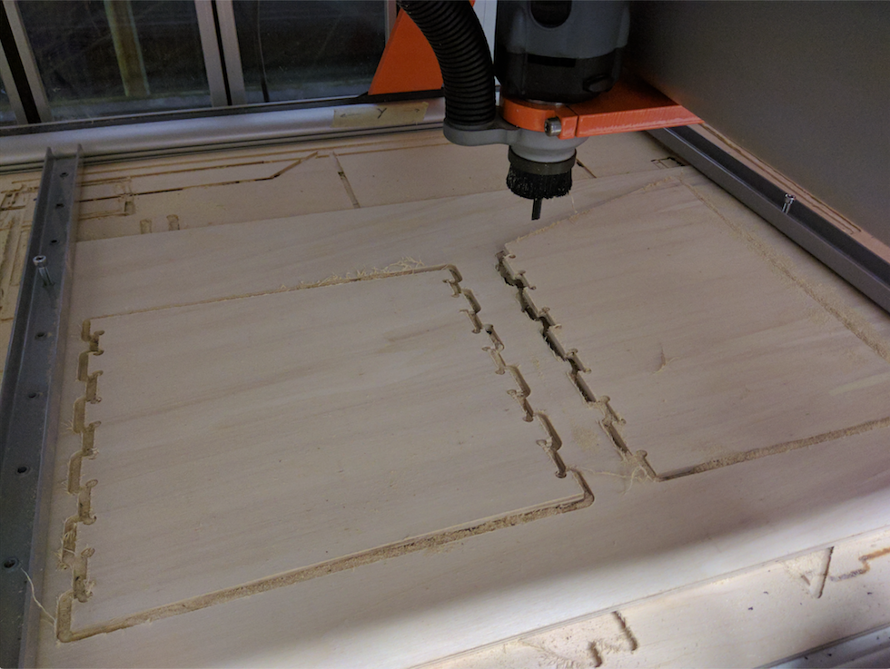
3. Check whether the object fits onto your plate in the milling machine. To check it fix your material in the machine with the help of screws so it does not move around during the mill process (as seen as an example in the picture underneath)
4. If the object fits onto the material move your drilling head onto the material in the Z-axis and press 'Zero all' again.
5. Move your drill head up again. Around 1cm from the material is fine. This is to be able to turn on the drill head without leading it to directly mill into the material.
6. Press the button 'Cycle Start' to start your mill process

During the mill process you can observe the status of the process in the stepcraft software.
Machine Setup: Parameters
- I used a feed rate of the value 300 to mill my housing. I chose that value as a faster one made a mill tool break in an earlier usage of the machine.
- I used a nut milling head with 4mm diameter.
Milling process
Turn on the drill head by reaching into the machine. Additionally, turn on the vacuum cleaner.
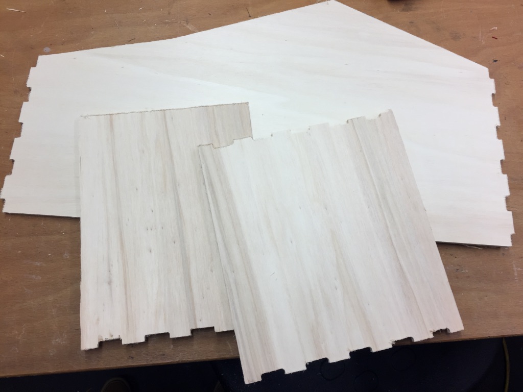
Assembling the house
What I learned about Joints
-
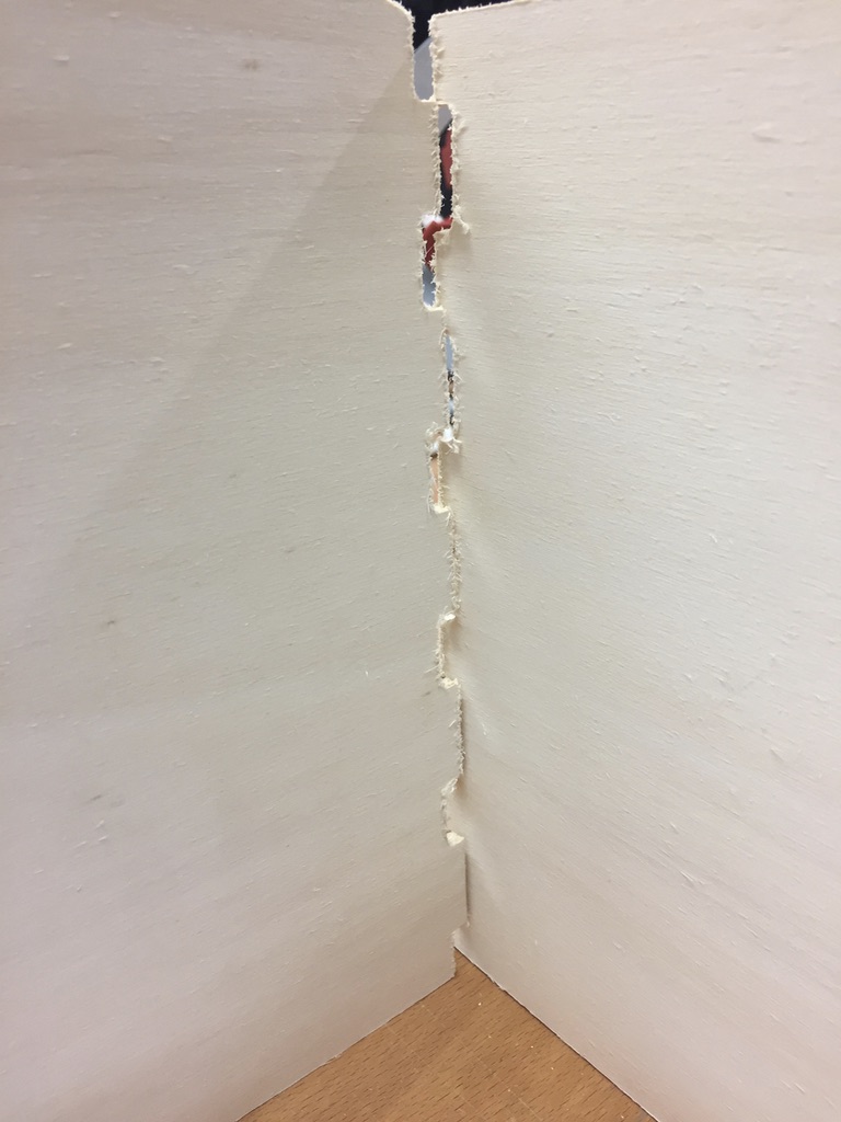
General fact: Producing objects that can be assembled and fit tightly is not the easiest process. You need to plan during the design process how you want the object
to look like in the end and accordingly choose the suitable joint type.
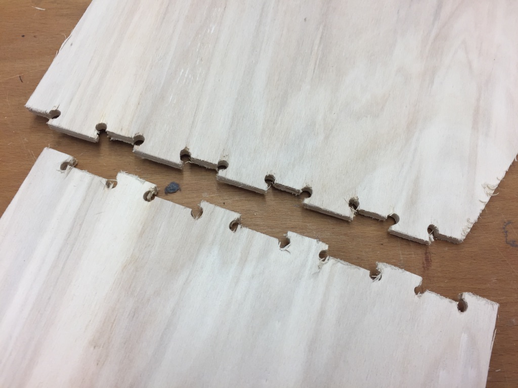
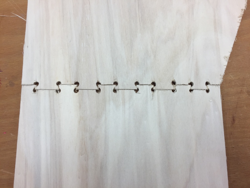
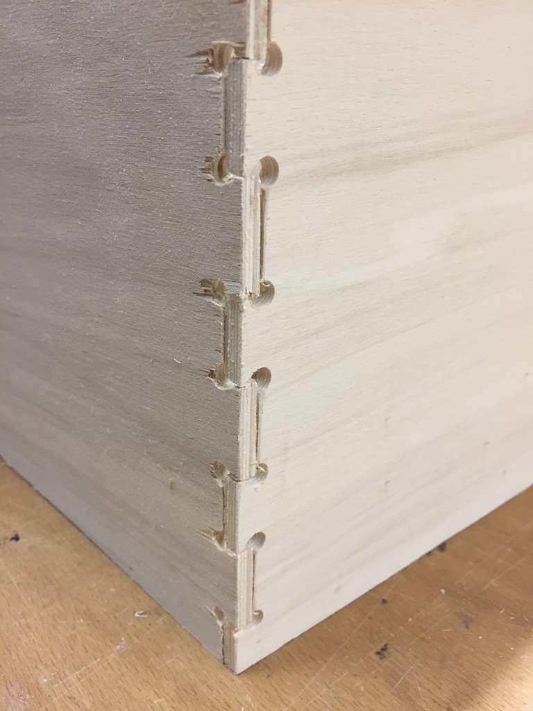
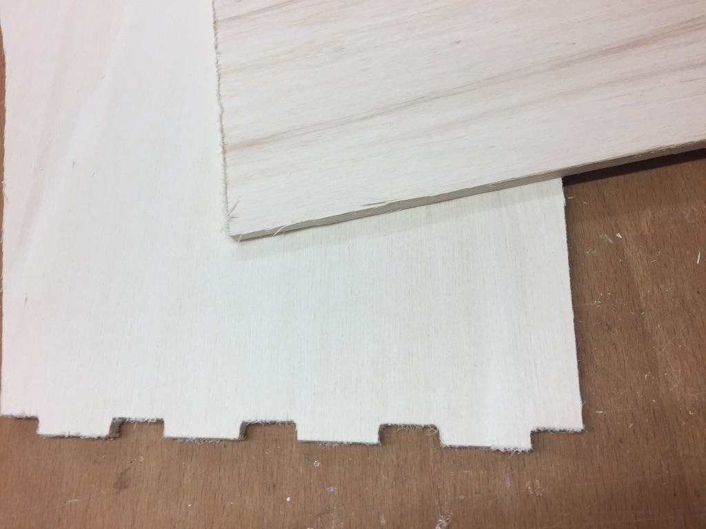
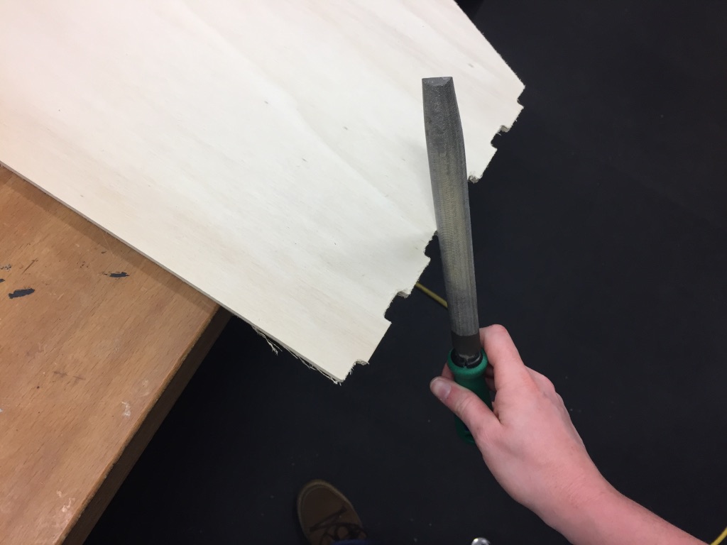
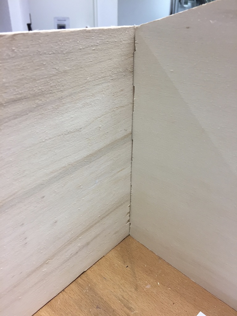
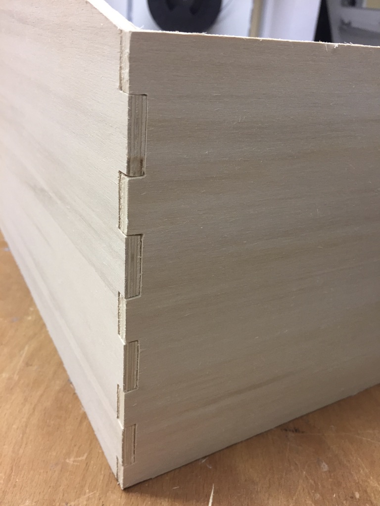
- To be able to connect parts I usually use finger joints, e.g. when using the laser cutter. The problem with finger joints when using the CNC mill is that the mill head cannot mill rectangular inner corners. It will always produce round inner corners. But round corners are not able to produce fitting parts.
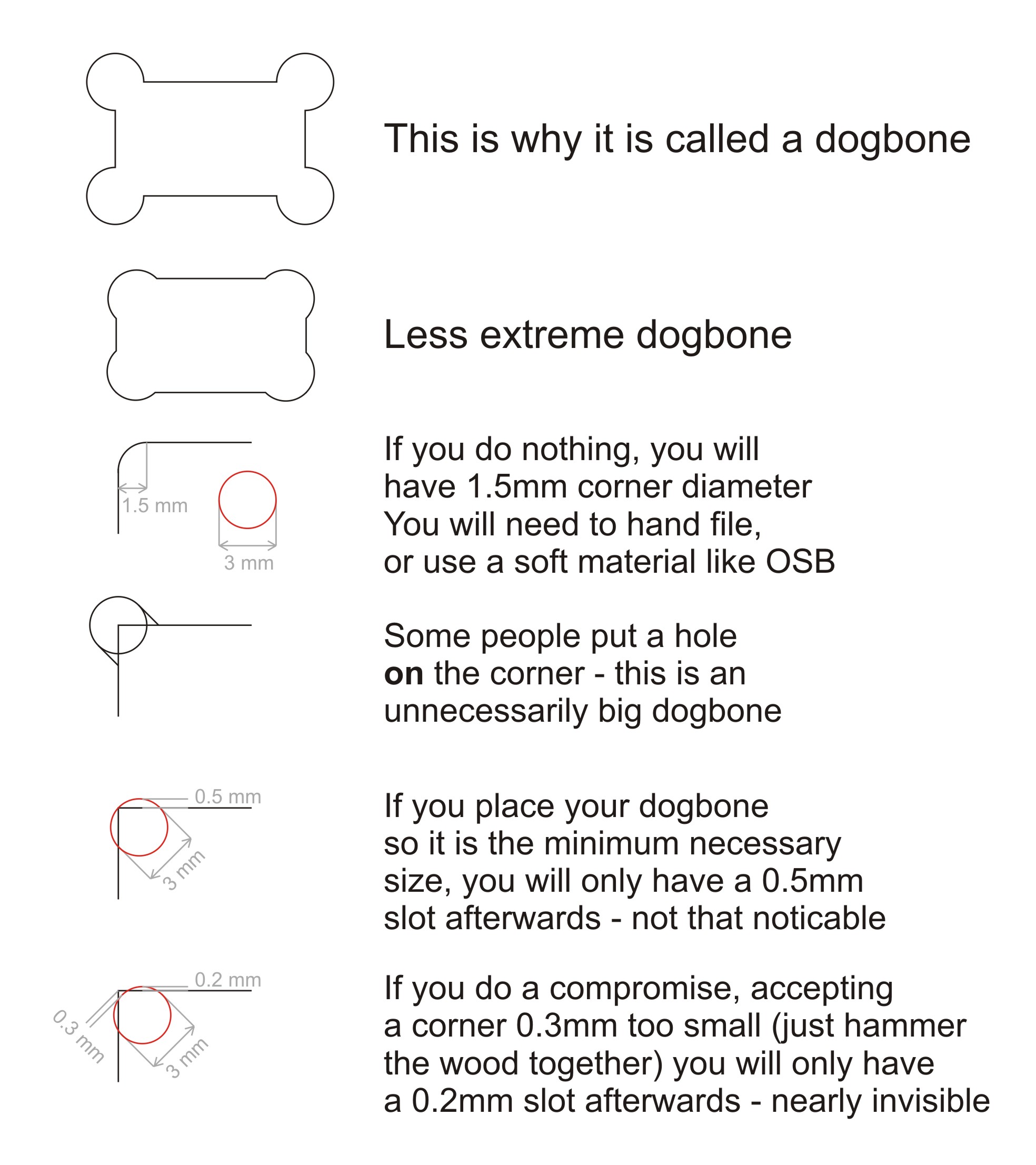
- One solution to produce tight fit parts is using dog bone joints. I found the following website concerning more elegant dogbones. The picture underneath gives very interesting information about dog bones design. When I used dog bones I just made use of a big round hole at the inner corners to produce fitting crib walls. But dog bones can look differently. You can design them nearly invisible. A very interesting fact to keep in mind for the future.
- While searching for ways how to produce a tight fit with a CNC milling machine I came across different types of other joints, e.g. blind joints, half blind joints, through joints etc. Even though flexures are not the classic joints flexures still open up the opportunity to form 3D objects by producing bendable material. More types of joints and information you can find here
How I used dogbones