Output devices
Introduction
This weeks assignment requires us to add an output device to a microcontroller board I've designed, and program it to do something.
Since this assignment is actually based on previously acquired skills, I will not go deeply into details of designing, milling and soldering, since they are documented already in Electronics Design and Electronics Production assignments.
Board design
I will first use the same board I made for an Input Device assignment.
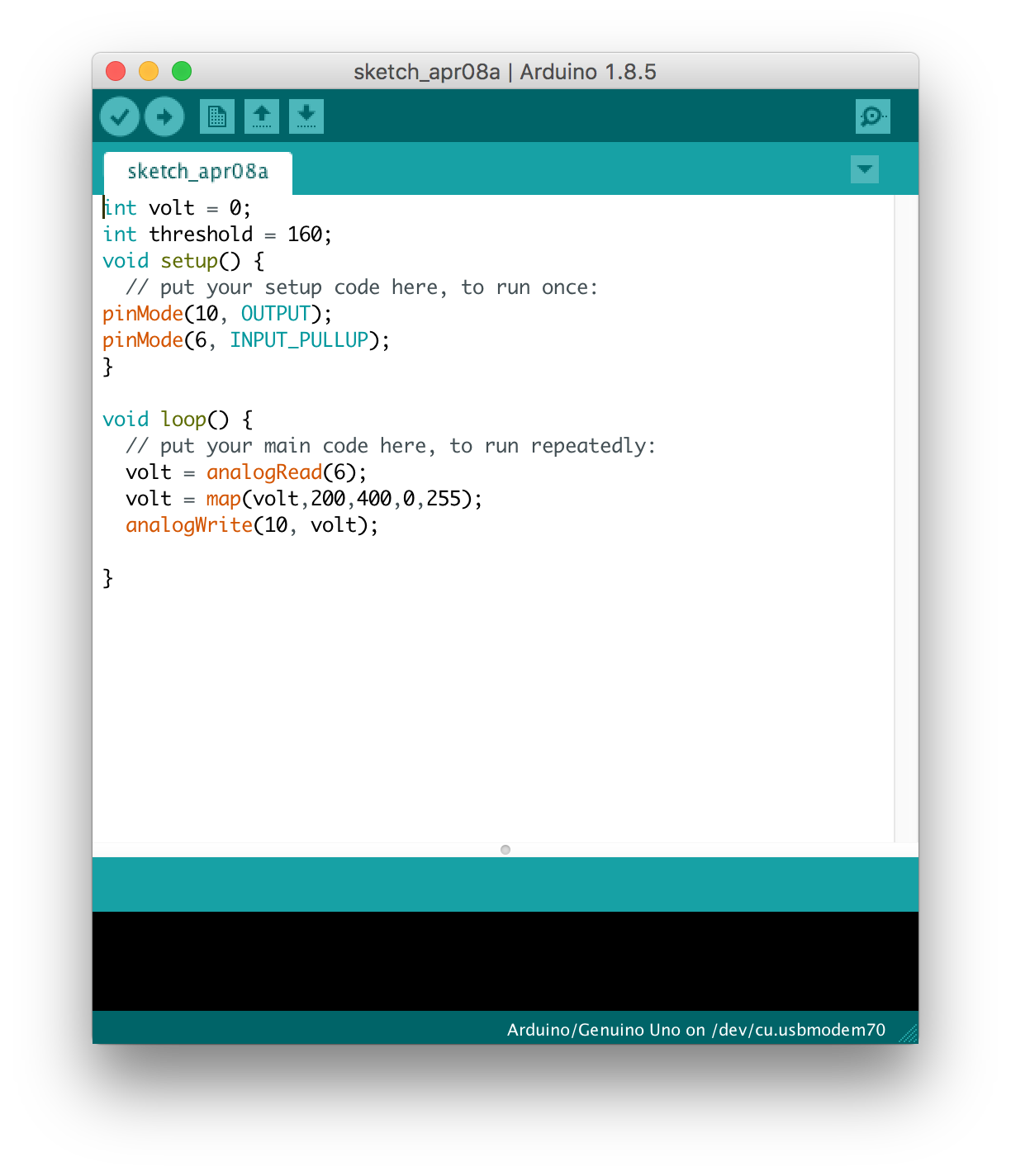
For an output device I decided first to use a simple LED. For my final project I plan to use an WS2812 LED, that will change colors according to the input(for example, water level sensor). Right now I am thinking about making an output device, that will indicate the light, put on the bright LED Strip with bright light(special for plants) and vice versa. In order not to waste any material I decided to use a breadboard for connecting LED and resistor to the board. Here is the Arduino code(can be downloaded at the very end of this documentation):
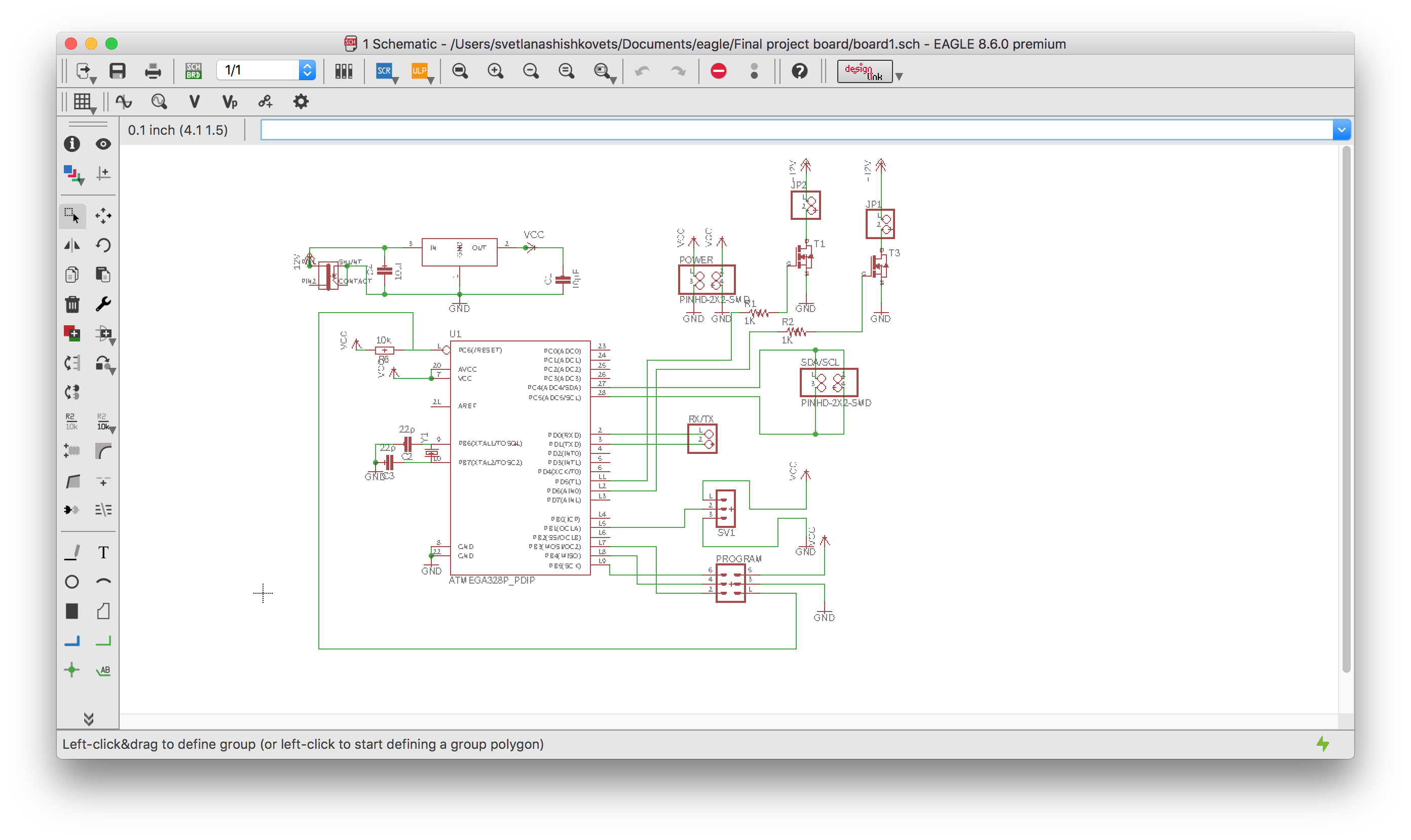
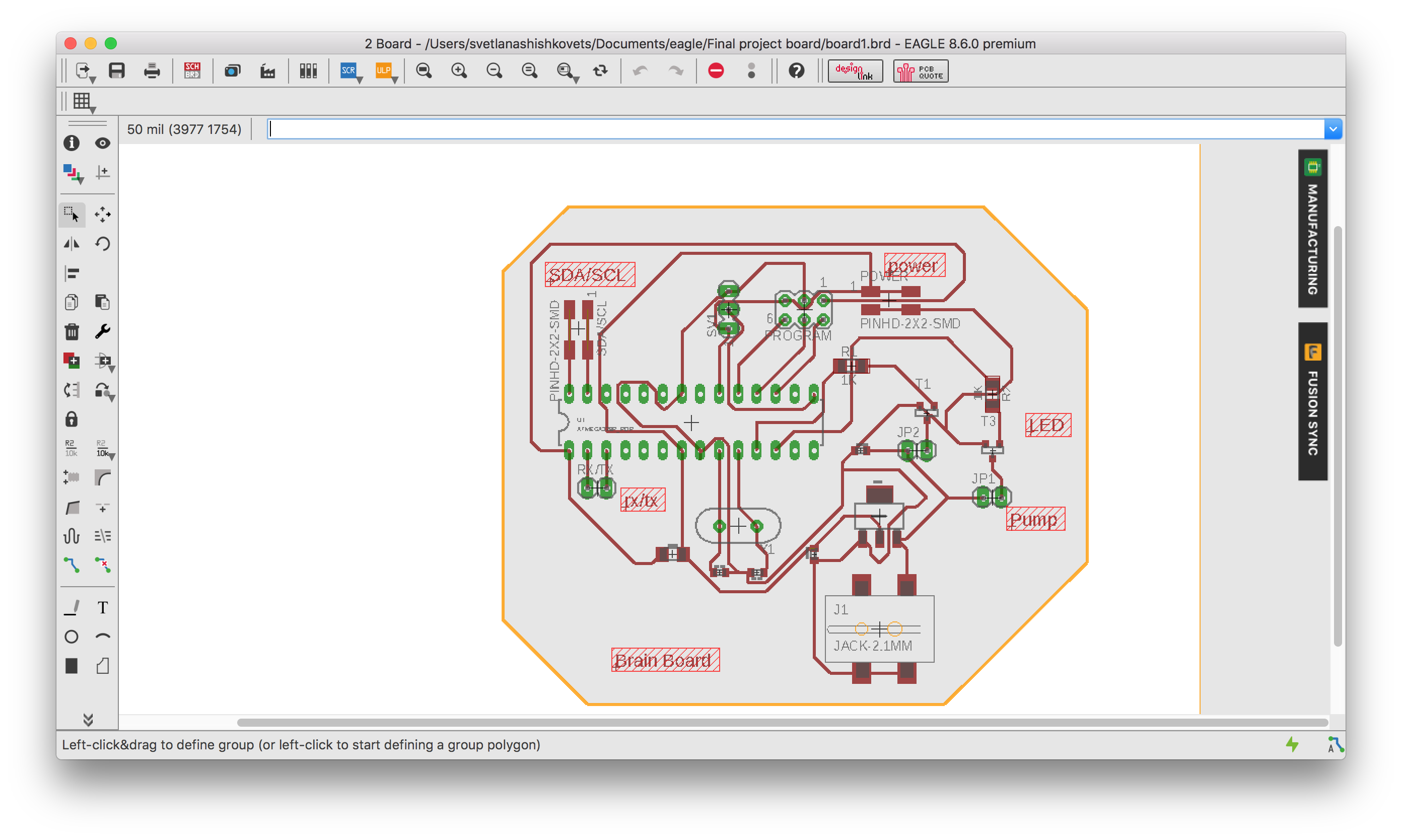
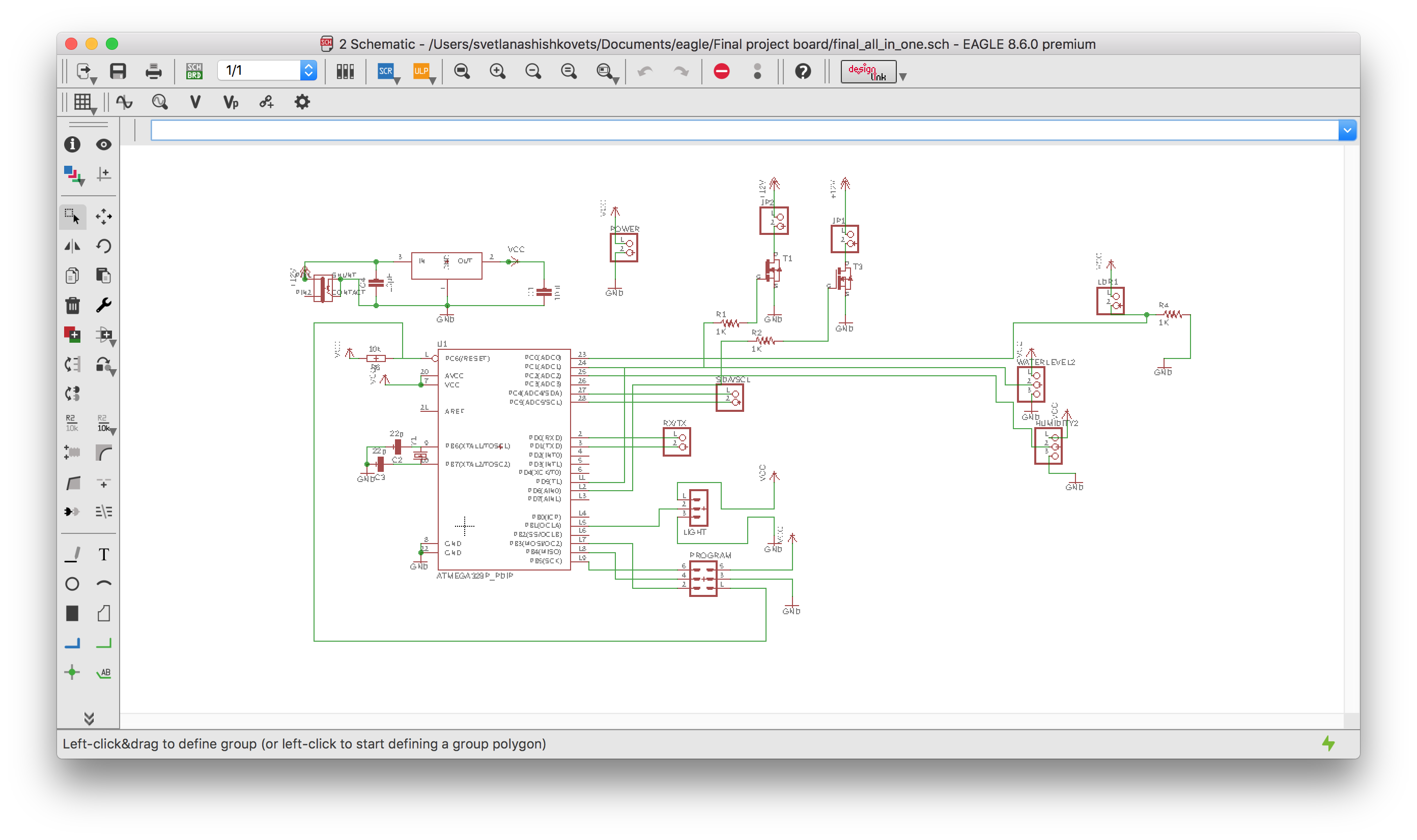
After that was done, I decided to create my output board. This board will turn on and off water pump and LED strip and will also change the color of WS2812. I started my schematic in eagle by adding all components needed:
- [Microcontroller] ATmega 328
- [Other] 2 MOSFET is short for Metal Oxide Semiconductor Field Effect Transistor. It is a voltage controlled field effect transistor. In my case will be used to control when to put Water Pump and special LED strip on and off. So with the usage of Mosfet I can control from my board (using 5V) the circuit with Water Pump/ Light (12V). The current that that is needed: for Water Pump - 400mA, for Grow Light - 550mA. More info about how the Mosfet works.
- [Other] Pinheads
- [2x3] Programming the ATmega using the VCC, RESET, MOSI, MISO, SCK & GND pins.
- [1x3] Pinheader for RGB LED
- 2*[1x2] To connect Water Pump and LED Strip
- [1x2] For the serial RX/TX communication
- [2x2] For SDA/SCL communication between boards
- [2x2] For powering other boards
- [Other] 2*1KΩ Resistor - Protects the MOSFET from too much current
- [Other] Crystal for measuring time including 2 capacitors. This setup is actually called an oscillator circuit.
- [Other] 10kΩ Resistor for the RESET pin on the ATmega.
- [Other] Voltage Regulator which will power the whole board by transforming the input 12V into 5V
- [Other] 2* 10µF Capasitors between ground and power before and after Voltage Regulator for smoothing the current and keeping the voltage more constant.
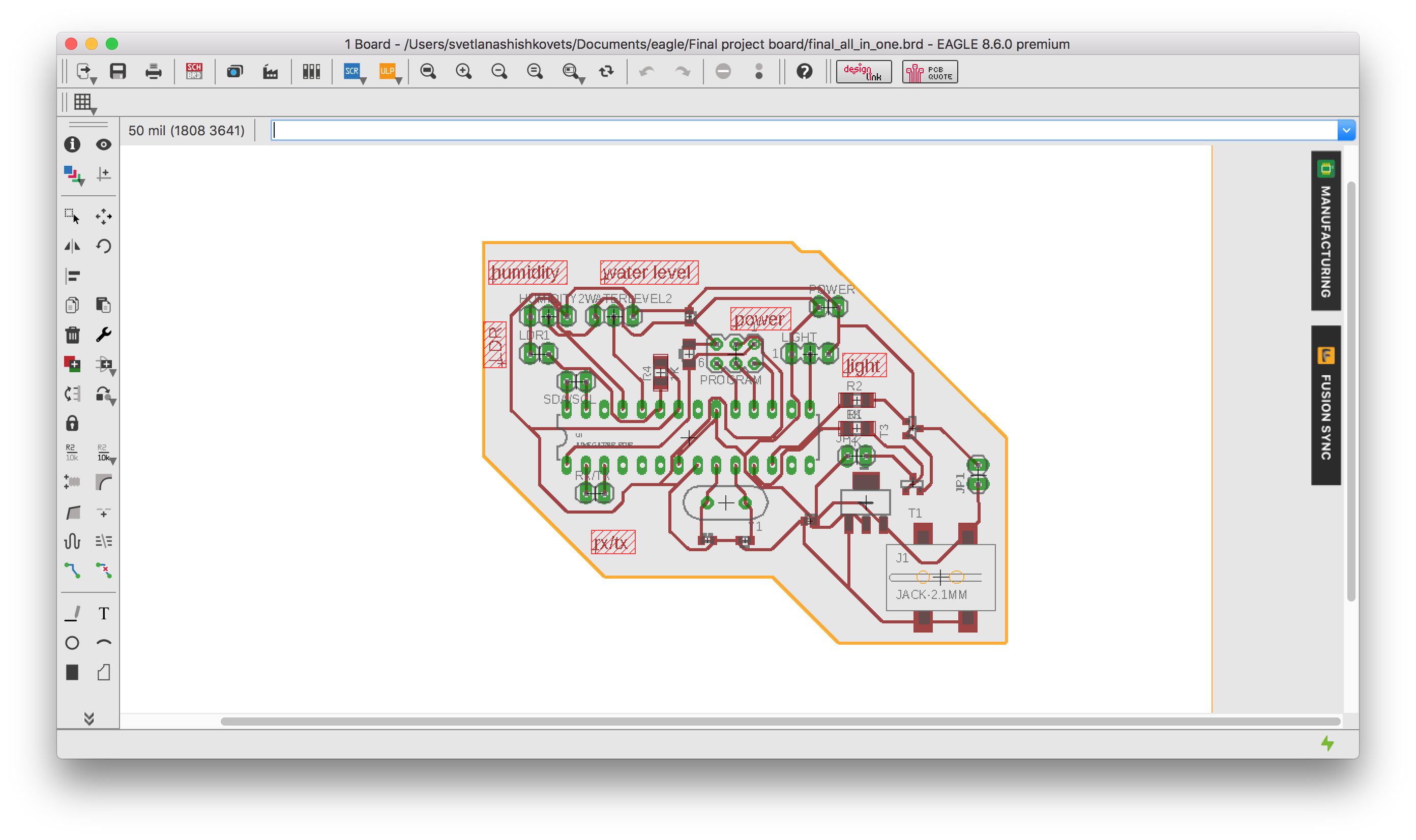
That is how my Eagle schematic and board looks like:
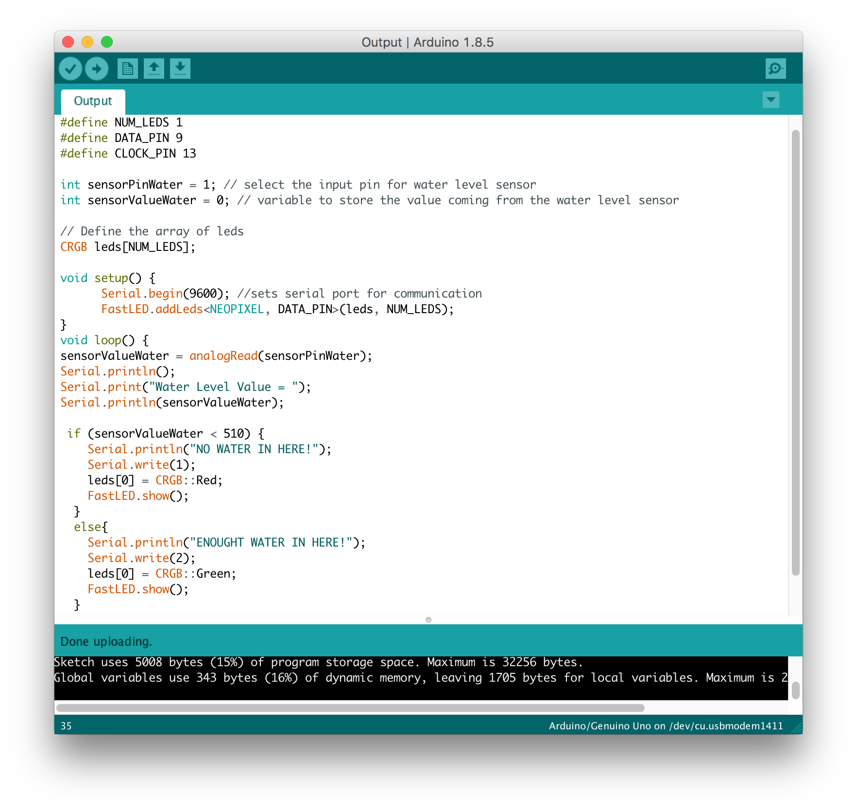
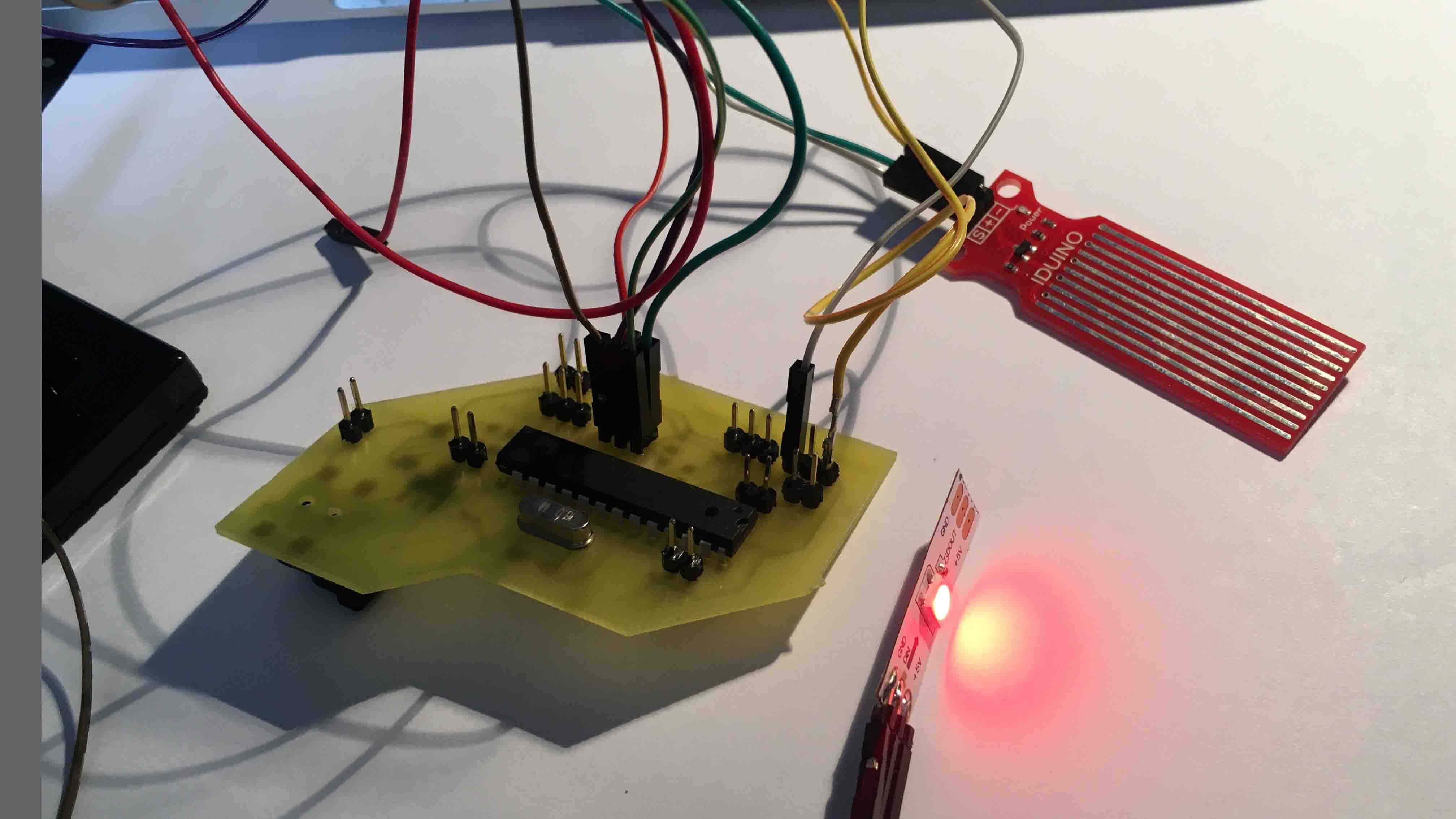
Then I did the same steps I explained before: Milling, Soldering, Running Bootloader. I used serial connection to communicate between two boards. For more info, how I did it, go to Networking and Communications assignment . As an output device here I used one piece of LED strip. I downloaded this Library in order to work with such an LED. Here is the scretch of my code where, depending on the input (water level) the LED goes green, when there is enough water and red otherwise. Since I Use the library, I can just easy write that in order to make WS2812 be green:
                leds[0] = CRGB::Green;
                FastLED.show();
Here is how it works:
After that I realized that ATmega 328 has enough pins for all my needs, that is why I merged all the components from two boards described above together. So now, depending on input from sensors, I will put on/off water pump and LED strip and the color od WS2812. So I designed a new board:
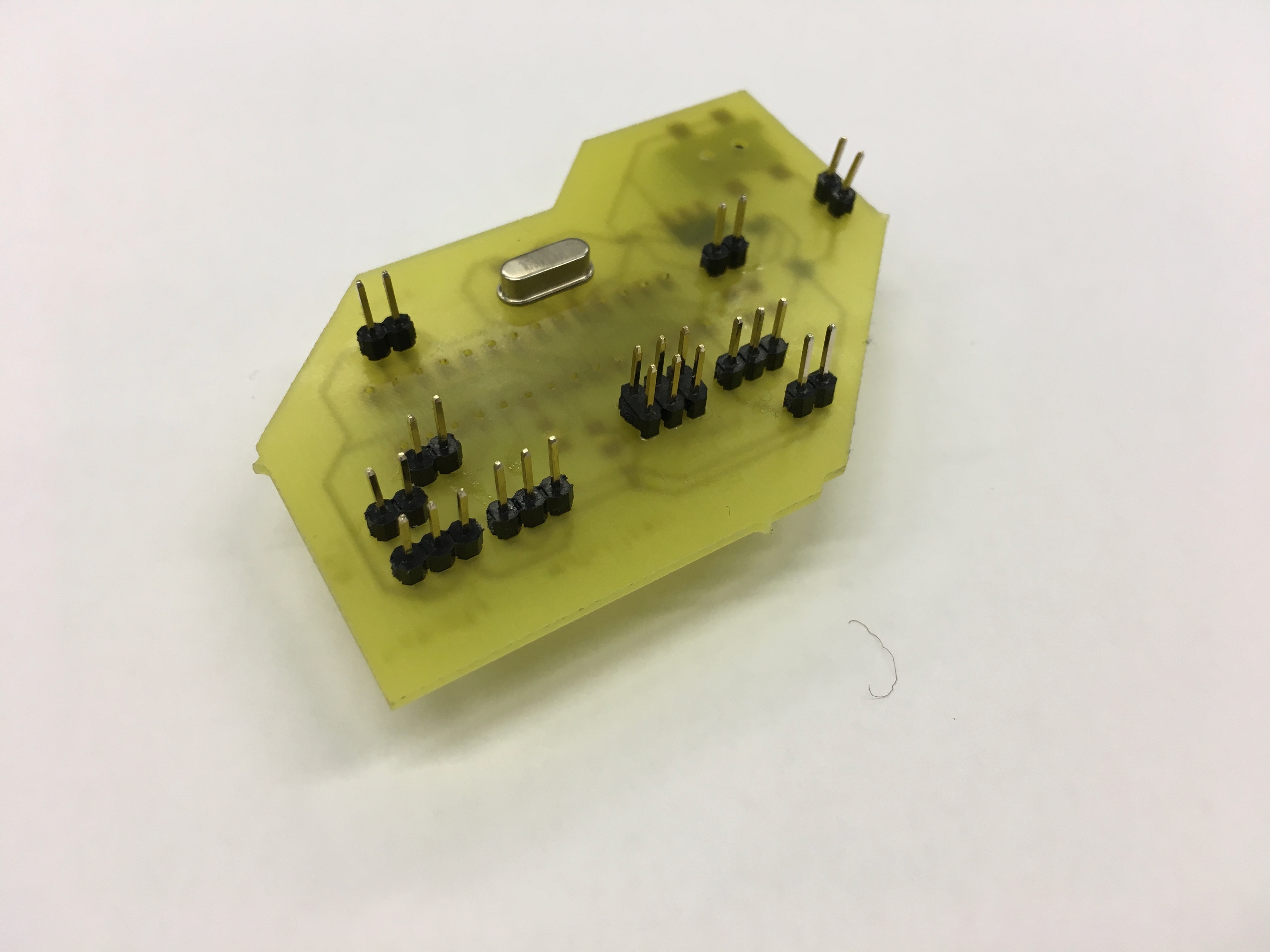
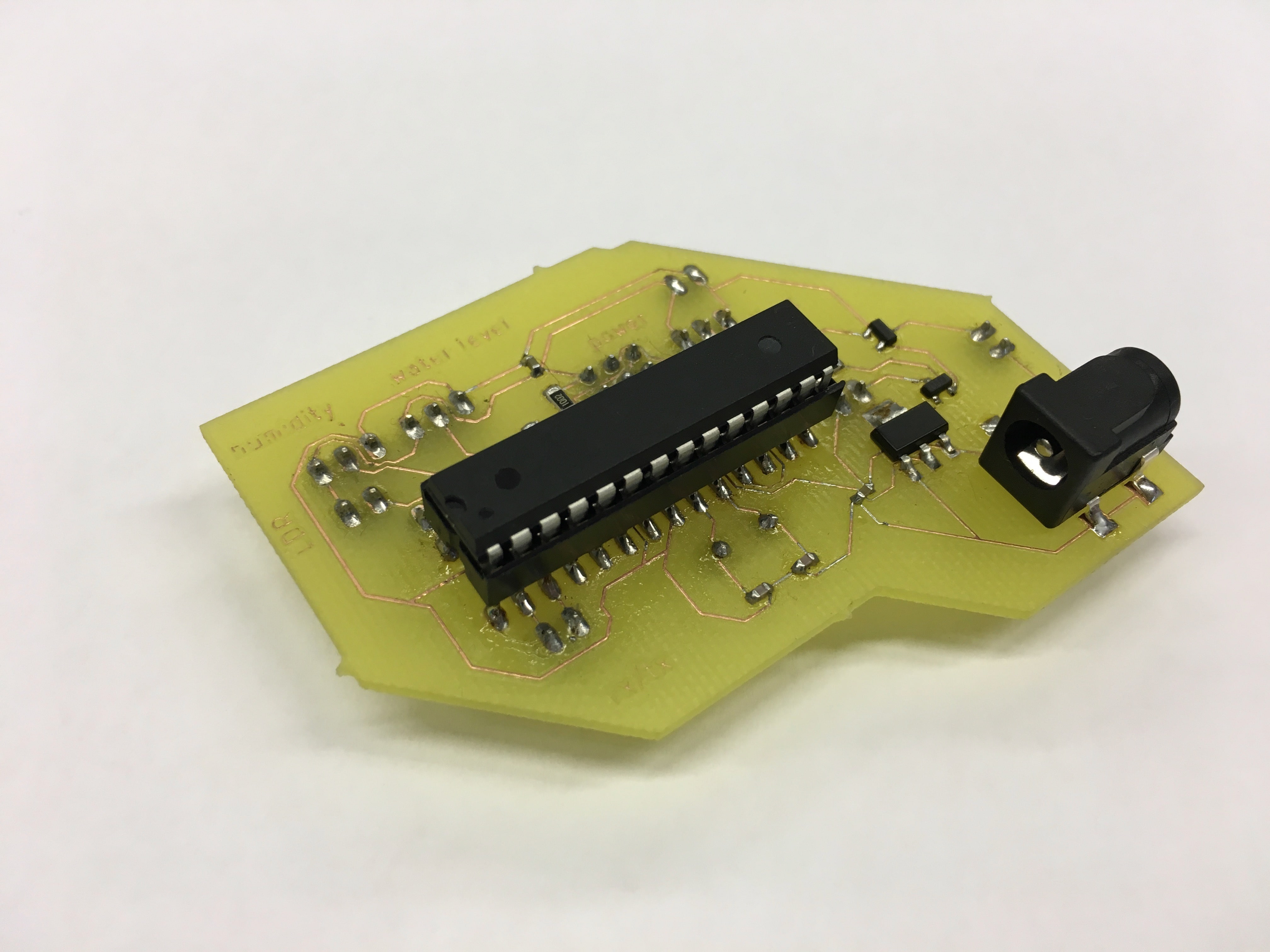
After soldering my board looks like that:
Then I did the coding. Again, I used Arduino as ISP for programming. The only new here, in code, is how to control Mosfet. Basically, if I want to turn my pump/light strip on, I just send to pin, that controls Mosfet, HIGH signal, otherwise LOW. So it is one pin for each Mosfet. This is done using function "digitalWrite(pin, HIGH)" and "digitalWrite(pin, LOW)". Here is my code:
#include "FastLED.h"
// define LED as an output for water level
#define NUM_LEDS 1
#define DATA_PIN 9
// determine input sensors
int sensorPinLDR = PC0; // select the input pin for LDR
int sensorValueLDR = 0; // variable to store the value coming from the LDR sensor
int sensorPinWater = PC1; // select the input pin for water level sensor
int sensorValueWater = 0; // variable to store the value coming from the water level sensor
int sensorPinHumidity = PC2; // select the input pin for humidity sensor
int sensorValueHumidity = 0; // variable to store the value coming from the humidity  sensor

// Define the array of leds
CRGB leds[NUM_LEDS];

void setup() {
  // put your setup code here, to run once:
  Serial.begin(9600); //sets serial port for communication
  FastLED.addLeds(leds, NUM_LEDS);
// MOSFET PINS
pinMode(PD5, OUTPUT);// PUMP
pinMode(PD6, OUTPUT);// LIGHTS
}
void loop() {
  // put your main code here, to run repeatedly:
  sensorValueLDR = analogRead(sensorPinLDR); // read the value from the sensor
  sensorValueWater = analogRead(sensorPinWater);
  sensorValueHumidity = analogRead(sensorPinHumidity);

  // Water level
 if (sensorValueWater < 510) {
    Serial.println("NO WATER IN HERE!");
    //Serial.print(0);
    leds[0] = CRGB::Red;
    FastLED.show();
  }
  else{
    Serial.println("ENOUGHT WATER IN HERE!");
    //Serial.print(1);
    leds[0] = CRGB::Green;
    FastLED.show();
  }

  // Humidity
   if (sensorValueHumidity < 110) {
    Serial.println("Dry Soil!");
     digitalWrite(PD5, HIGH); //turn the pump on
  }
  else{
    Serial.println("Moist soil");
     digitalWrite(PD5, LOW);// turn the pump off
  }

  // LIGHT
   if (sensorValueLDR < 300) {
    Serial.println("Not enought Light");
     digitalWrite(PD6, HIGH);// turn the Lights on
  }
  else{
   Serial.println("Enought Light");
     digitalWrite(PD6, LOW); //turn the Lights off
  }

 delay(1000);

}
And here is the video how everything works: