WEEK 17
WILDCARD WEEK
ASSIGNMENT DETAILS: Design and produce something with a digital fabrication process not covered in another assignment, documenting the requirements that your assignment meets, and including everything necessary to reproduce it.
INTRODUCTION:For this week's assignment I chose to work with the embroidery machine to make a soft circuit button. I used a Brother PE-770 digital embroiderer and some Gikfun Conductive Thread. The embroidery software I have chosen is SewArt. This soft push button will be used in my final project as a preset button for the Color Clock.
INITIAL TEST
Before designing the push button I decided to do a quick test using a pattern that was already loaded on the machine. I was skeptical as I read a bad review on Amazon and I could not get much of a reading with a multimeter.
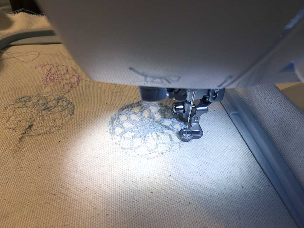
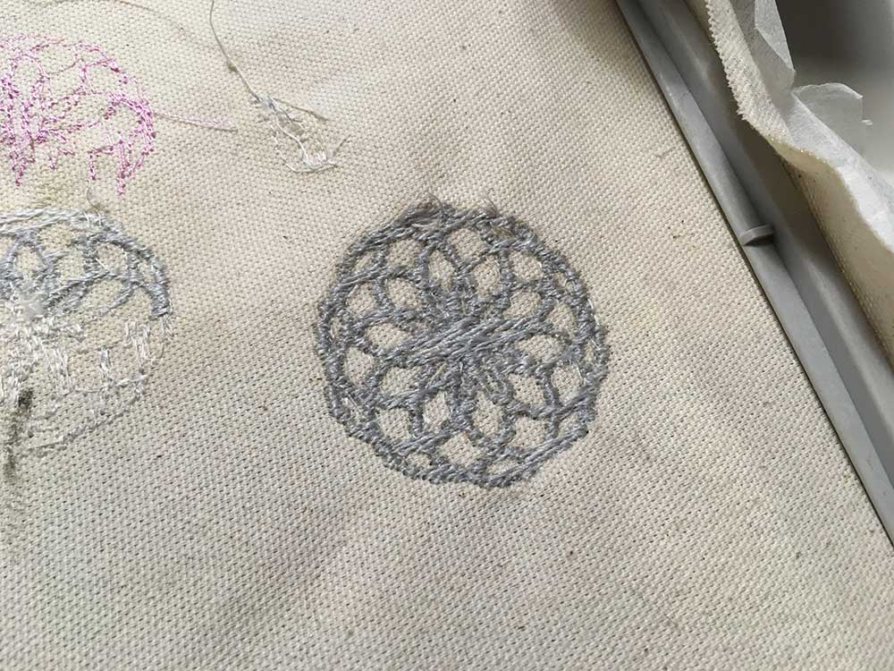
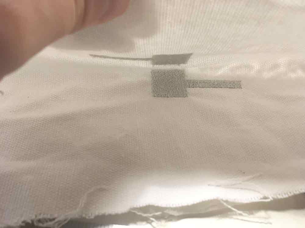
This particular object was designed using Turtle Art. It looks ok from far but up close I find it rather messy. Although it is a bit of a complex pattern to match with different stitching. When I have more time will evaluate the stitching patterns.
At first when probing the thread with using the diode/continuity test mode I could only see some occasional numbers fluctuating suggesting that the material was somewhat conductive but not enough for continuity. After a bit of patience I was able to get a continuity reading in some very specific spots.
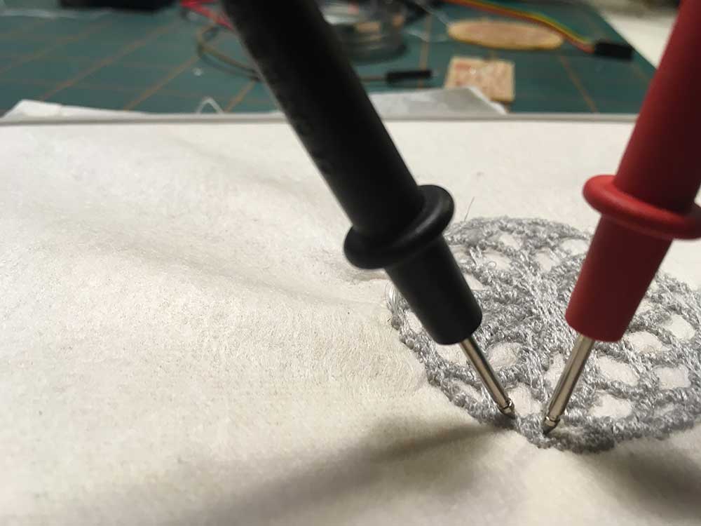
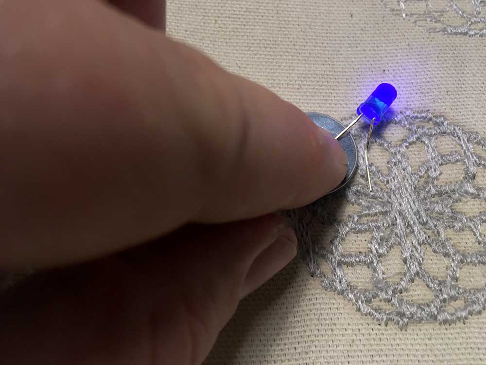
Surprisingly, it was easier to light an LED than it was to get a continuity reading. I was excited to see that this stuff actually works and is specifically only good in applications like embroidery where the thread has to be tightly woven.
I broke a few needles during this test in the end I discovered it was probably due to thread tension. The spool of thread was too big so I wound some up on a bobbin and placed in in the thread holder. It may have wound a bit tight. The other thing was that I used regular thread in the bobbin. It is possible the conductive thread reacted poorly with it. Moving forward, I decided to put conductive thread in the bobbin as well which seemed to help the conductivity as well as I did not break any more needles.
EMBROIDERY
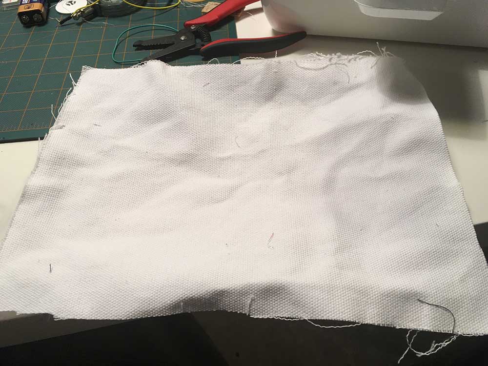
Now that I had confidence in the material I was using I setup the machine for a new job. I took some white canvas, and cut a sheet roughly the size of the 5" x 7" embroidery hoop.
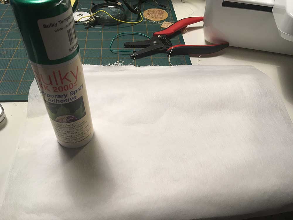
Next, I applied some Sulky KK 2000 temporary adhesive spray and applied some Sulky Tear Easy stabilizer to the back of the piece of canvas.
I pressed it into the hoop. I think I should have left more fabric on the sides so I could pull and apply more tension. I learned how to do all this from Vince Arcuri's thurough, albeit lengthy, Youtube tutorials
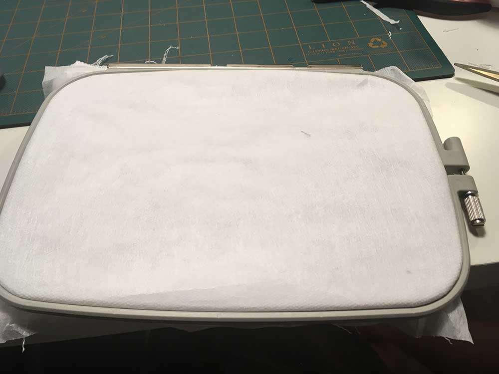
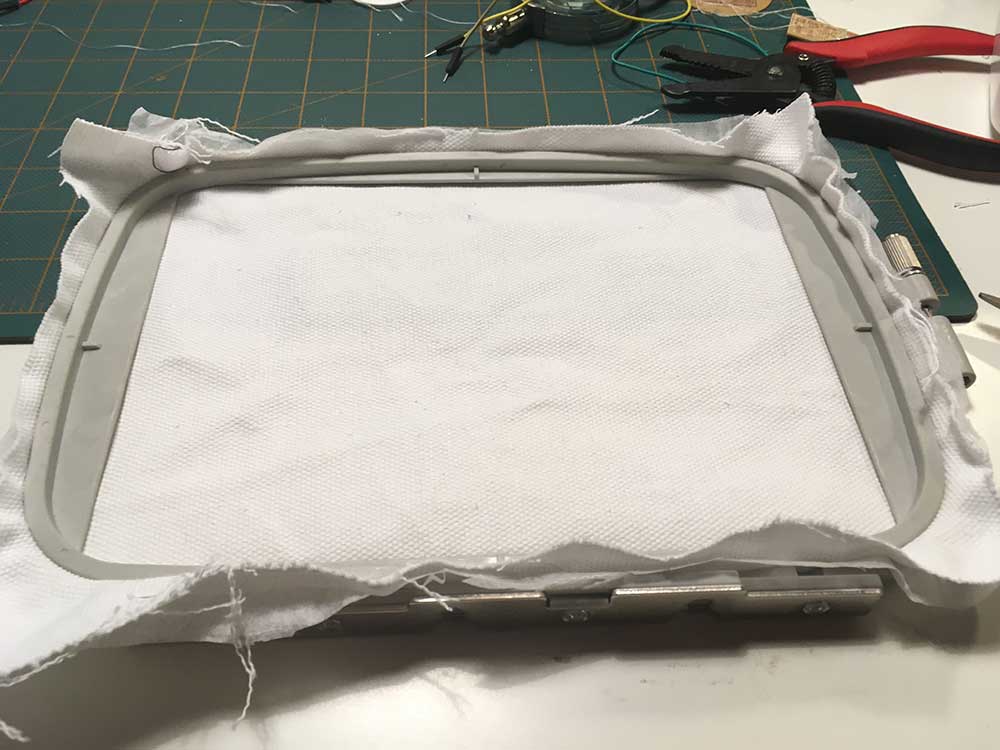
In the above image, the stabilizer should be face down and the fabric side face up.
---> Preparing the embroidery file
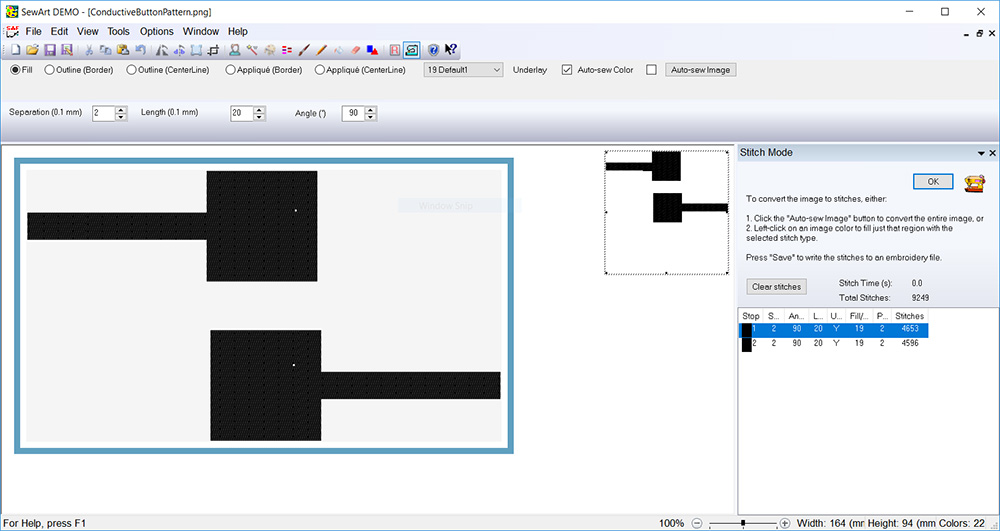
Using SewArt is very easy. I am sure there are levels to this like any software. But for basic stuff, it was an easy process. I am trying the demo version but will probably be buying it as it is not too expensive. I designed the button pattern in Adobe Illustrator and imported the SVG file.

Because of the square pad shape I tried a 90º stich thinking it would run a pattern parallel to the sides of the square. The rest of the settings were default. I selected the stitching feature and highlighted my design. My design is one color and I chose only one sticth pattern.
---> Separation 2
---> Length 20
---> Angle 90º
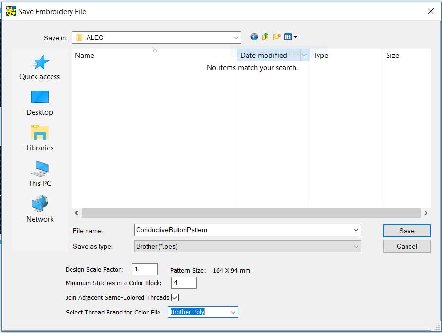
When it was time to export my embroidery file I made sure to choose Brother (*.pes) format. I did not know what kind of thread to compare this to so I kept it in the Brother Poly family.
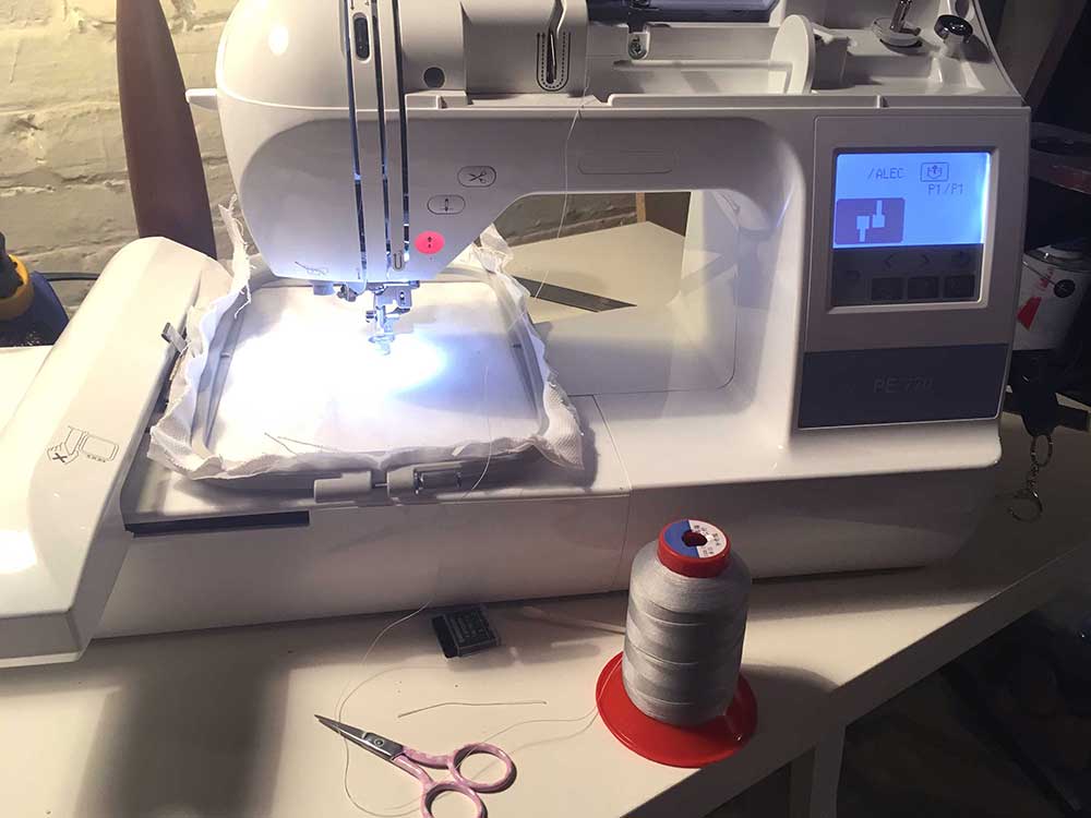
---> loading the machine
Once my file was loaded onto the machine I threaded the machine. I kept the giant spool of thread on the table next to the machine. This worked fine but I kept an eye on it to make sure it didn't catch or tangle. Also, as mentioned, I loaded conductive thread into the bobbin as well.
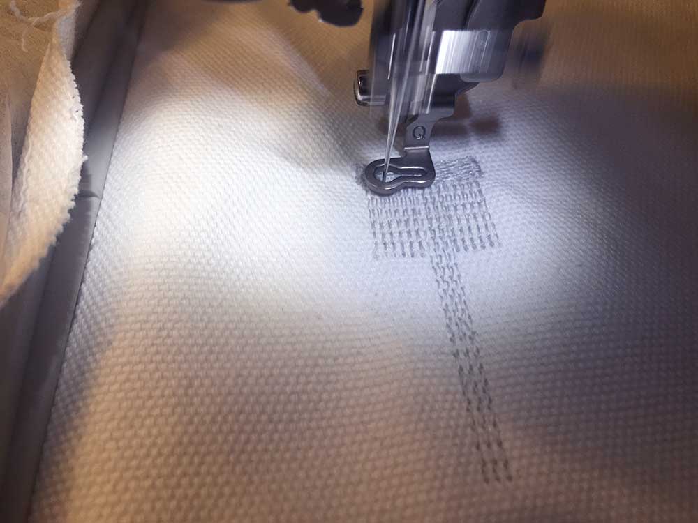
The window on the machine displays the stitch count. I did not change position or scale.
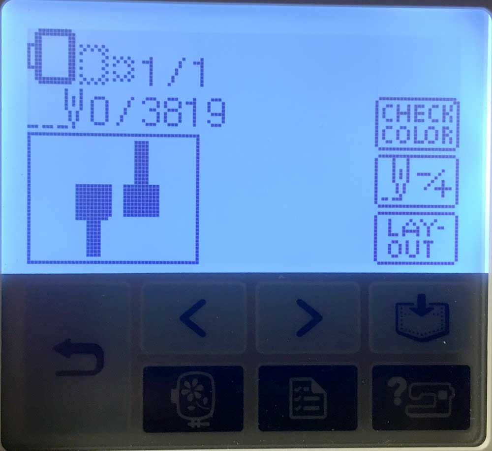
The job started without a problem. I paused it a few times thinking I heard the thread breaking but I was being cautious. You can see clearly the 90º stutch pattern. I will really play with this in the future. You can change stitch patterns based on the shape of your design and I am sure this can yield some interesting results.
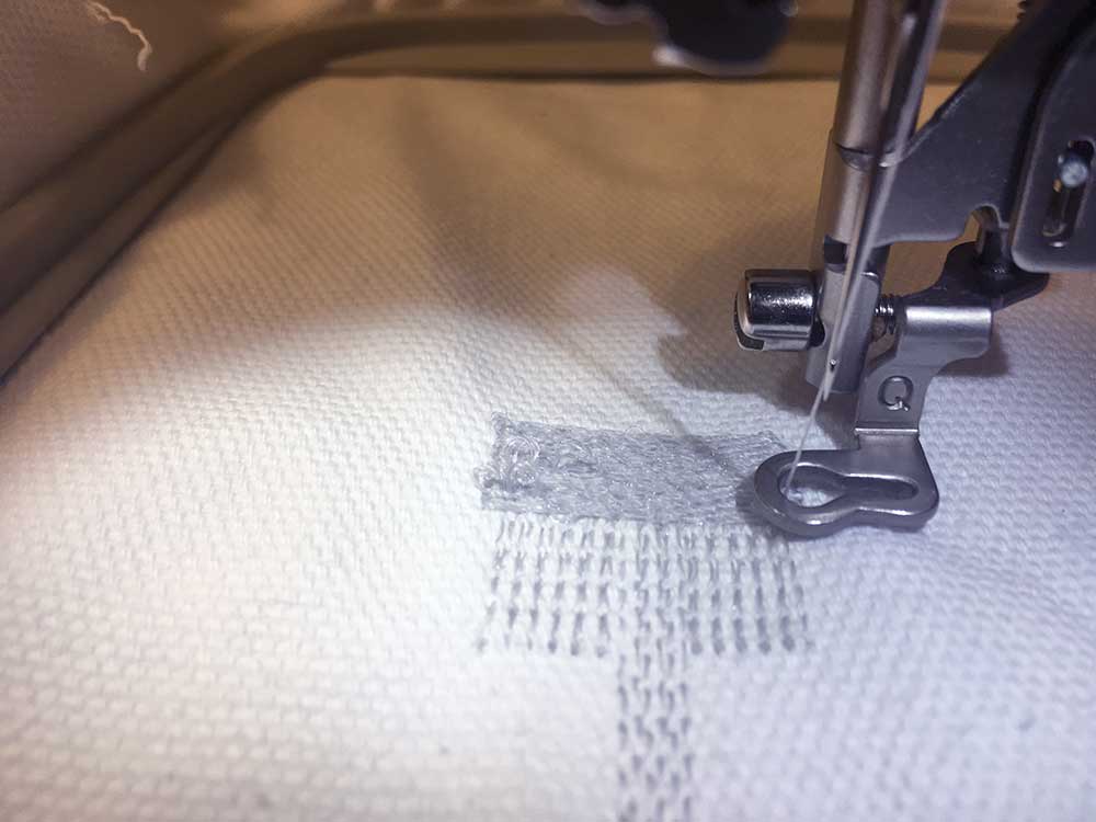
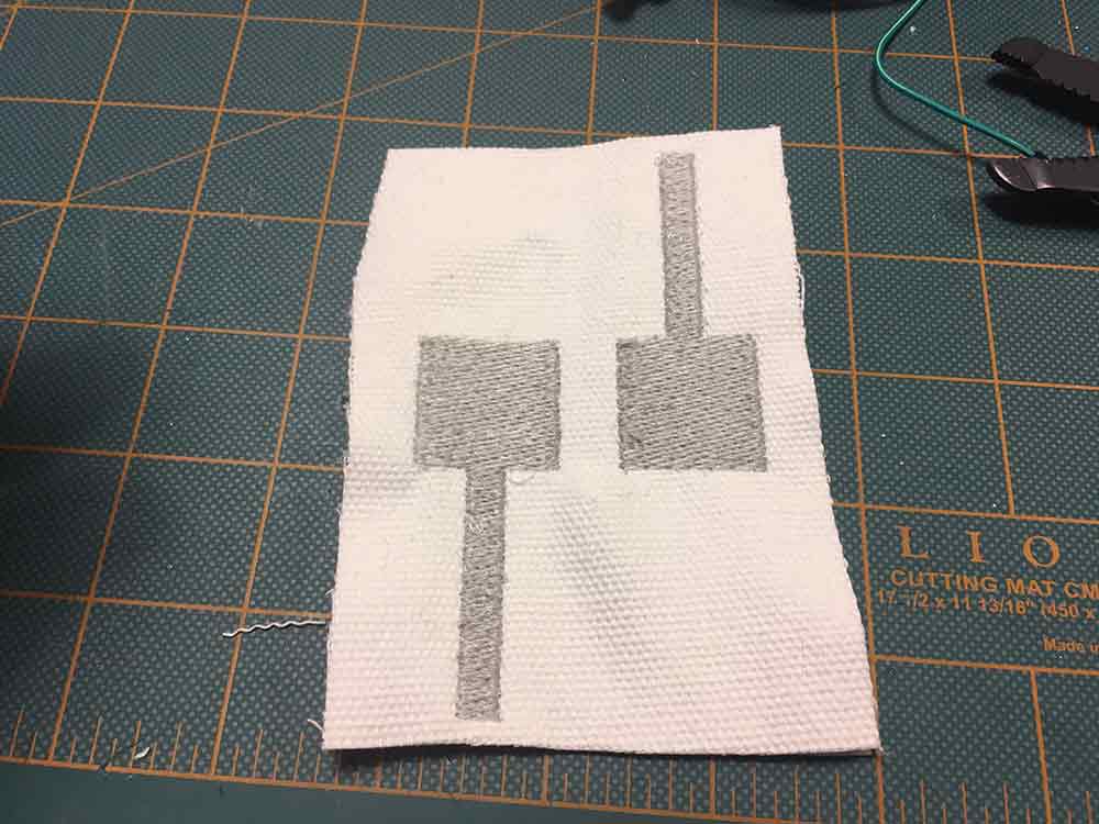
It camehe out as expected. There were a few loose stitches on the edge of the design. I will need to check and see what that is but like any machine it is probably related to calibration. I did not have the luxury of time on this assignment and I wanted to test the conductivity more than I wanted to test the look. I do find that the stitching on the side of the stabilizer looked cleaner.
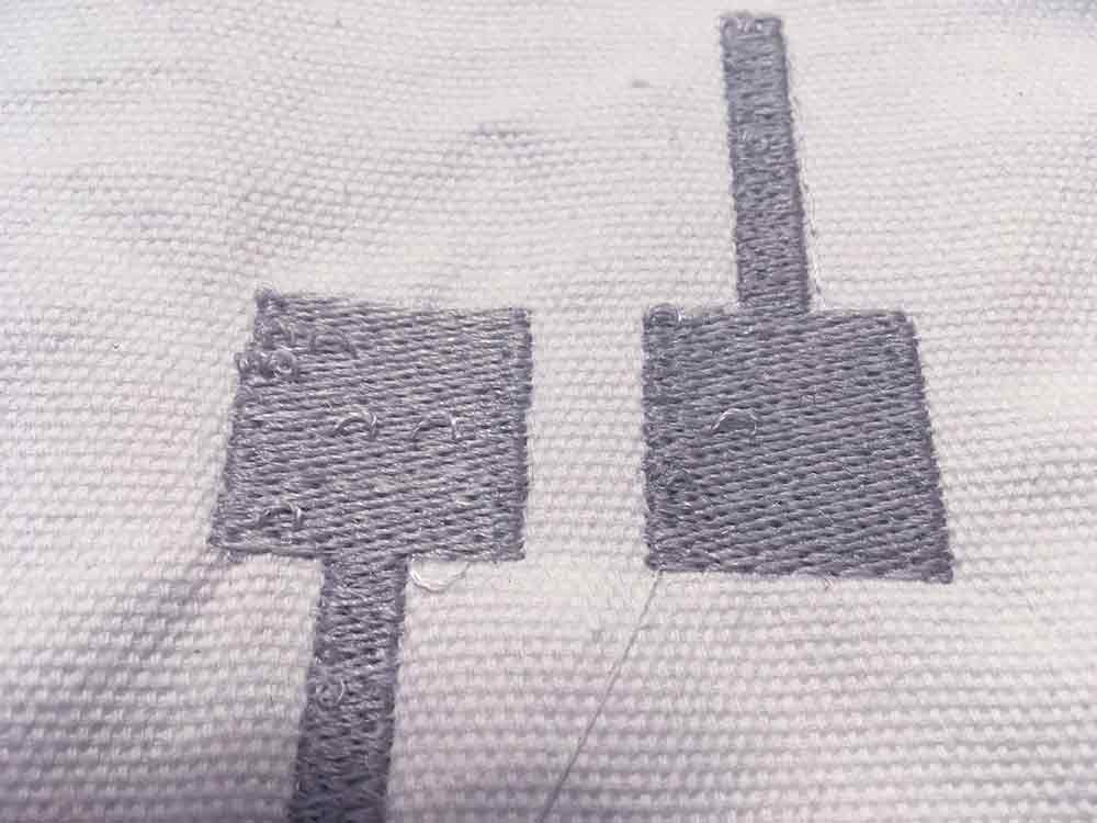
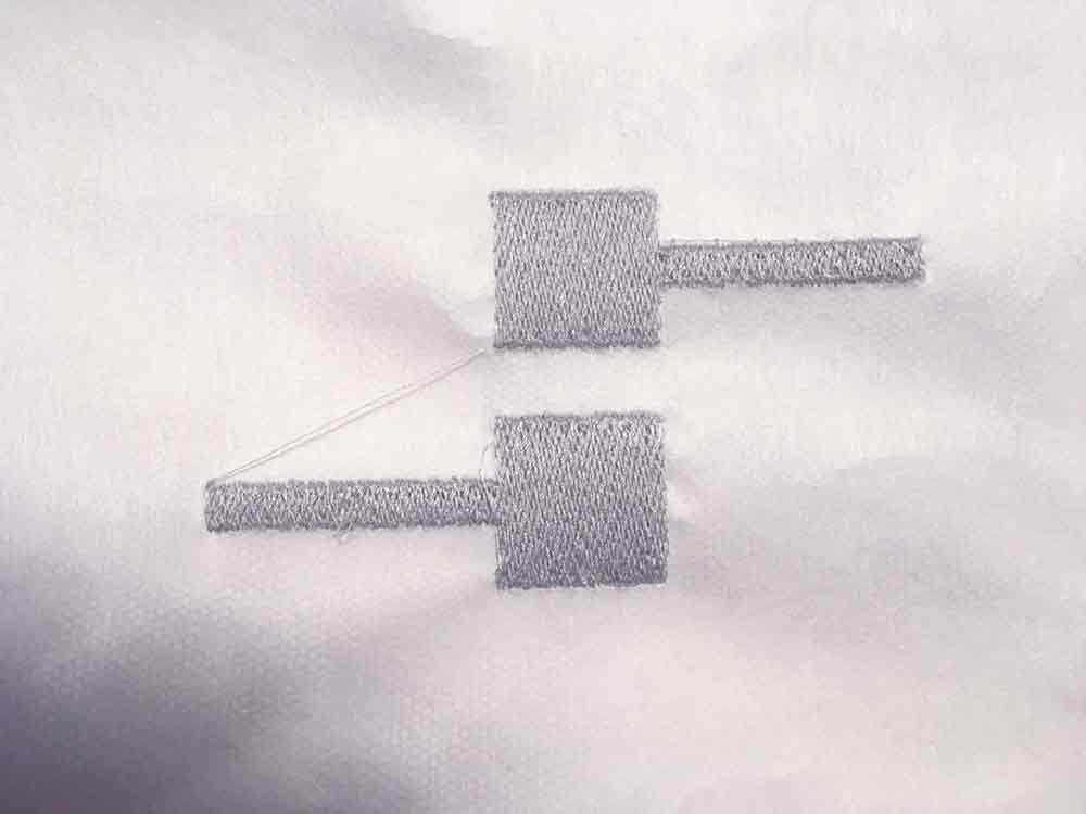
I designed this pattern so that you could just fold it into a push-button. I ended up dropping this idea but it worked nicely. The pads align as they should.
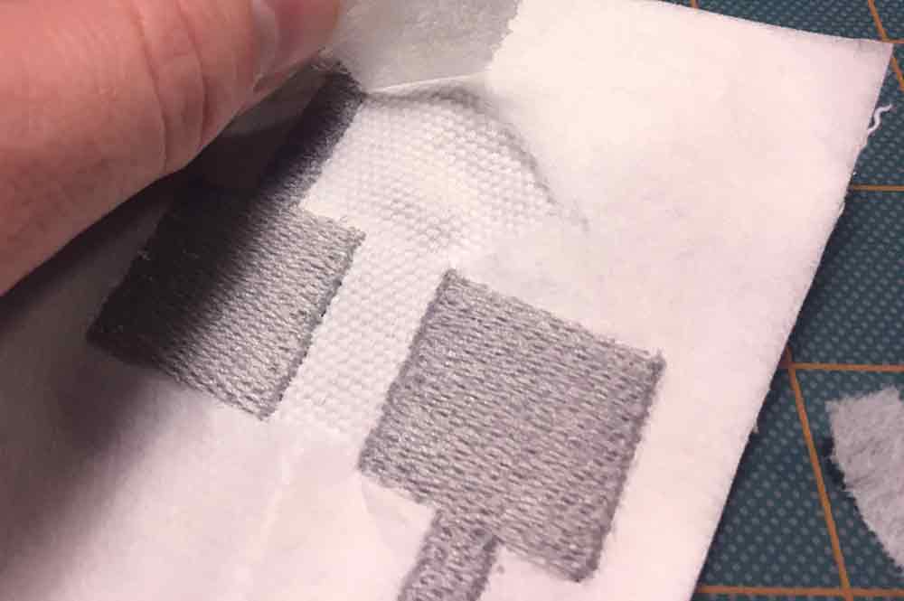
I cut away the excess material and I took off the tear-away stabilizer. It came off really easily.
EMBROIDERY
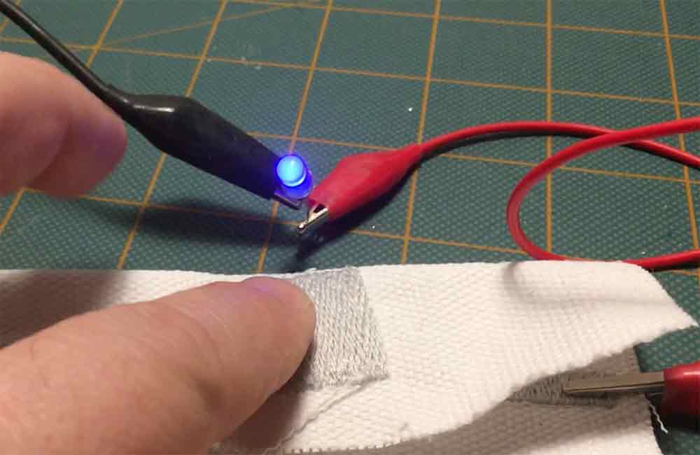
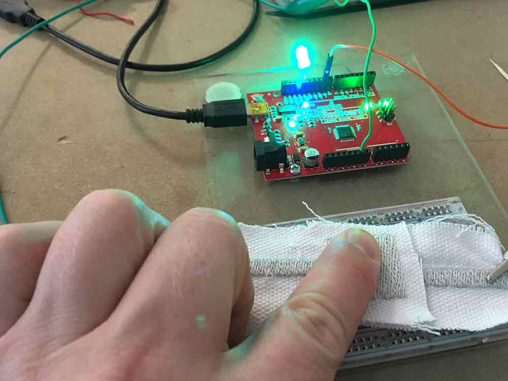
Making the push button was fun. I still have work to do on it so that it can be used in my final project. After the embroidery was done, I hooked up some aligator clips and and LED to a coin cell battery. I sandwiched the battery between the embroidered pads.
It worked effortlessly. The conductivity is far better with the conductive thread in the bobbin. The next step was to try and read a signal and guage how good this would work with a microcontroller.
I hooked the threaded push-button to an Arduino and pulled up the basic push-button example to turn on the LED on Pin13. Again, it worked really well. The main issue, is isolating the pads when you are not pushing. I noticed that these embroidered pads have enough resistance that they can be used as presure sensors. However, I need to make sure that they are not accidentally triggering things so I will have to check the threshold and sensitivity. I tried adding a pull-up, and changing the placement of the alligator clips. Some testing still needs to be done on this.
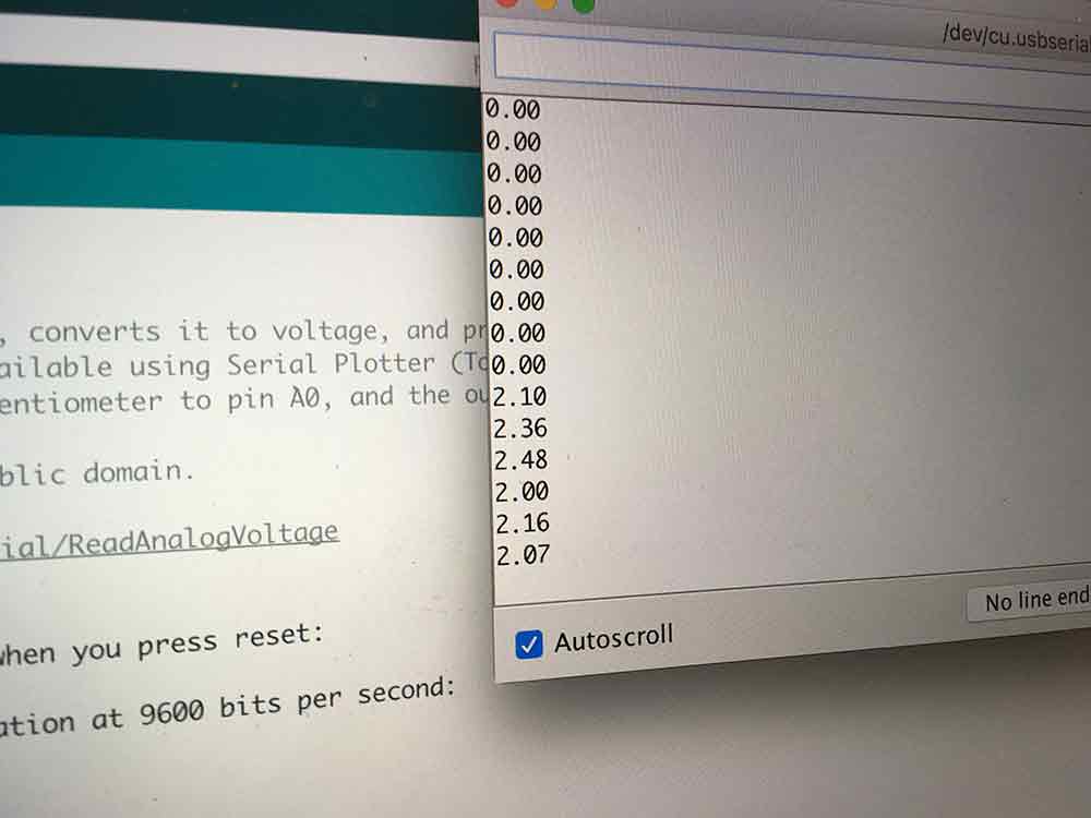
---> reading the sensor values
I decided to try using velostat in between the pads to help isolate them when they are not being pushed. I could also use conductive foam pads which have more spring. I will test this more with my finl project. In this example I am reading the voltage in the serial monitor of the Arduino it was plugged into. I got a reading between 0 - 2.50v
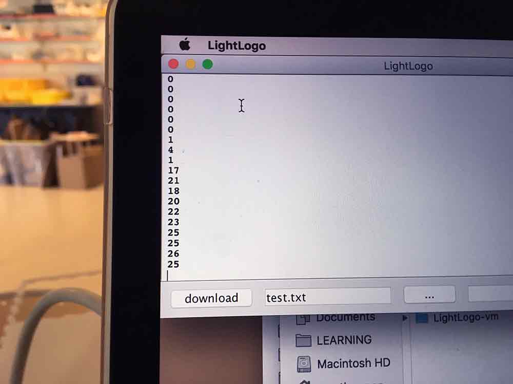
The next test was to read the pushbutton using Logo that I pushed onto the Arduino. Using this code:
loop [print sensor0 wait 100]This just reads the A0 pin on the Arduino and prints it in the monitor. The values matched what I was getting in the Arduino although multoplied by ten. 2.5 is read as 25.
The last step was to try and control a NeoPixel ring with the button. I compiled this simple code in Logo and pushed it onto the Arduino.
to startup
ht
loop [repeat 1[print sensor0 wait 100]
changering
]
end

to changering
ifelse sensor0 = 0 [setc red] [setc green fd 1 ]
endNOTE:For this test, I am using LightLogo which is Brian's designed to work with NeoPixels. It is equivalent to a custom library. ht in the above example refers to hide turtle. In this flavor of Logo, the turtle is represented as a white pixel. For more information and references to LightLogo go to the link below.
---> LightLogoReferenceV3.pdf
Here is the button interacting with the NeoPixel ring using the above code. Works really well.
ASSIGNMENT FILES
---> Button Pattern - Illustrator
---> Button Pattern - .pes
---> NeoPixel Button Test - .txt