LASER CUTTING
TESTING PARAMETERS
For this assignment, I was unable to work with the group at echoFab so my tests were conducted at the LCC Fab Lab. I used the same test pattern on the same machine as at echoFab which is a Trotec Speedy 300 60w. While both labs have the same model of laser engraver, it is possible to require different settings as nuances like the age of the laser tube might make it so that our findings are different. The same plywood on LCC's machine might require slightly different settings on the machine at echoFab which is a bit older and sees more traffic. We decided to try different materials so that we can compare more general aspects of the material settings. To see Marc's results, click HERE. To see George's results click HERE.
I decided to do some tests with natural canvas and Trotec Plywood which are two materials that I had on hand that differ from the materials being tested by others in my group. An interesting future test would be to determine the difference in settings between machines of different age. Different labs will have different results with the same parameters.
JOB CONTROLTrotec uses a software called Job Control. You can assign different functions to different colors. A drawing with multiple colors can be processed in multiple ways. For example, cutting different depths within the same job or prioritizing zones. If you are manufacturing parts or multiples, job control can be sequenced to help speed your jobs. Any fills or strokes that are bigger than 1pt (Adobe Illustrator) will be seen as engravings while hairlines and strokes less than .1pt (Adobe Illustrator) will be seen as cut lines.
Most mistakes occur when color or stroke widths are not set right. What is good about Job Control is that it makes it easy to catch mistakes in your drawing before you cut. The worst case would be to cut an intricate pattern that is meant for paper or wood on a more flamable material like cardboard. The default setting should be weak on purpose in case a user forgets to check property settings. However, it is important to get into the habbit of double checking your material settings before running the machine to avoid surprises and wasting material.
USEFUL LINKS
Trotec has a good set of tutorials and useful information to start from.
Laser Parameter Basic Settings
Laser Parameters for Trotec Materials
CANVAS
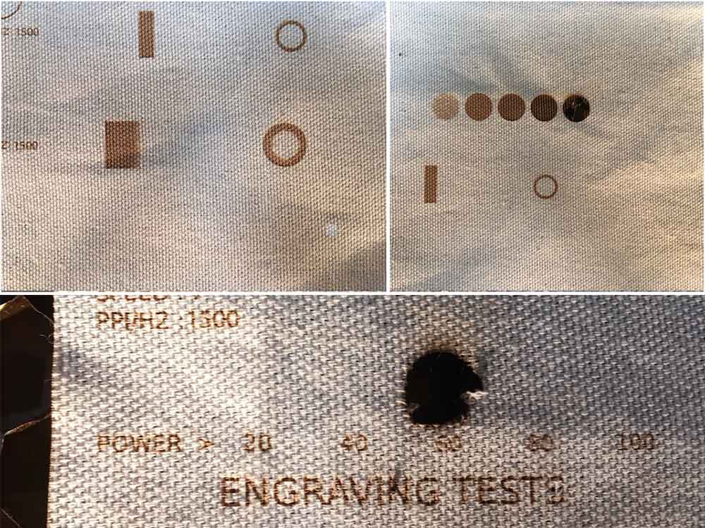
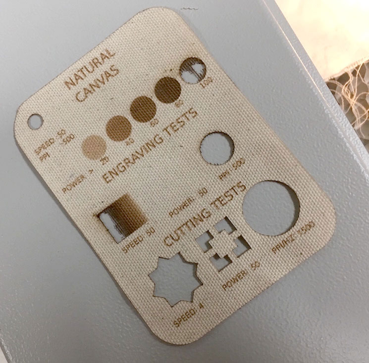
I started with testing the cutting of canvas. I lowered the power and the PPI significantly and used the initial settings for paper which were included in the Job Control software. Even though you can get good cuts at higher power settings I prefer to find the lowest power settings needed. As the Co2 laser ages, you can make small adjustments to compensate. If you are not careful, novice users of the machine, like many k-12 students, will be putting a lot more power into jobs than necessary.
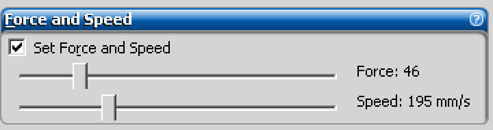
For the cut test I settled on 50% power and I adjusted the speed for 8 different cuts. The sweetspot was at 50% power with a speed of 4. The material cuts through but maintains just enough tension to keep the material attached. This means the edges of the fabric are less charred.
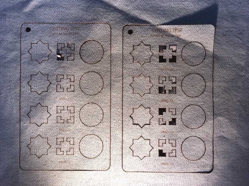
Once my initial tests were done I had a good idea for the minimal power settings needed to cut the canvas and a threshold for the engraving.
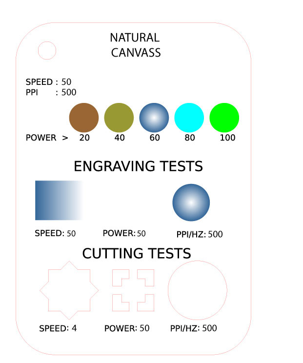
The ideal settings for Canvas on a relatively new Trotec Speedy 300 60W machine are the following:
---> Engraving: power 60, speed 50, PP1 500,
---> Cutting: power 50, speed 4, PP1 500,
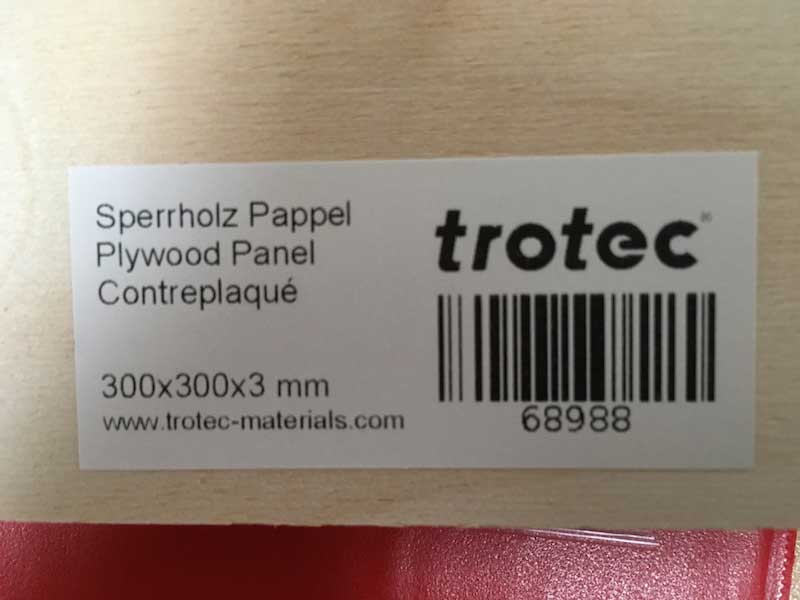
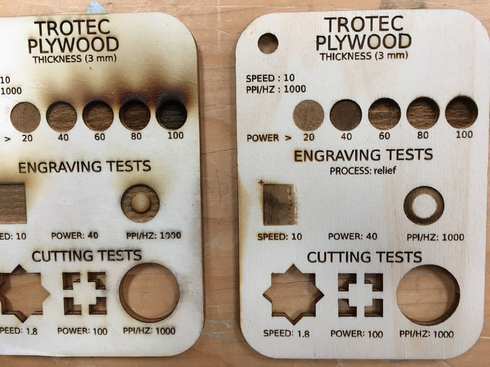
TROTEC PlYWOOD - 3mm
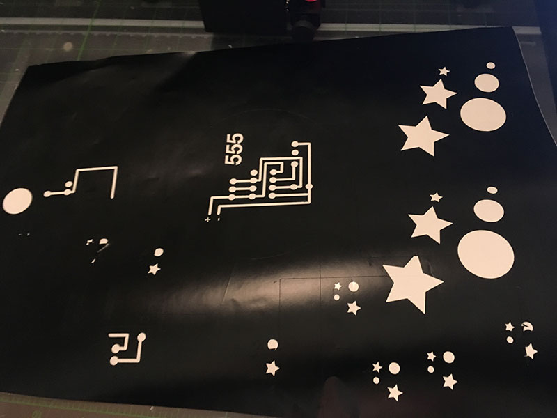
Trotec sells an engineered plywood that is ideal for laser engraving. It is more expenive but is very flat and apparently contains less of the nasty stuff you might find in generic plywood. The wood is much lighter than generic plywood and does not require the same settings. One of the things I dislike is seeing laser cut plywood with lots of burn marks. This is hard to control sometimes when you jump into a cue on an unfamiliar machine in a lab and I won't toss a good cut just for the look of it unless it is specifically necessary. The goal in this test is to find the minimum cut settings required to cut Trotec plywood with no burn marks.
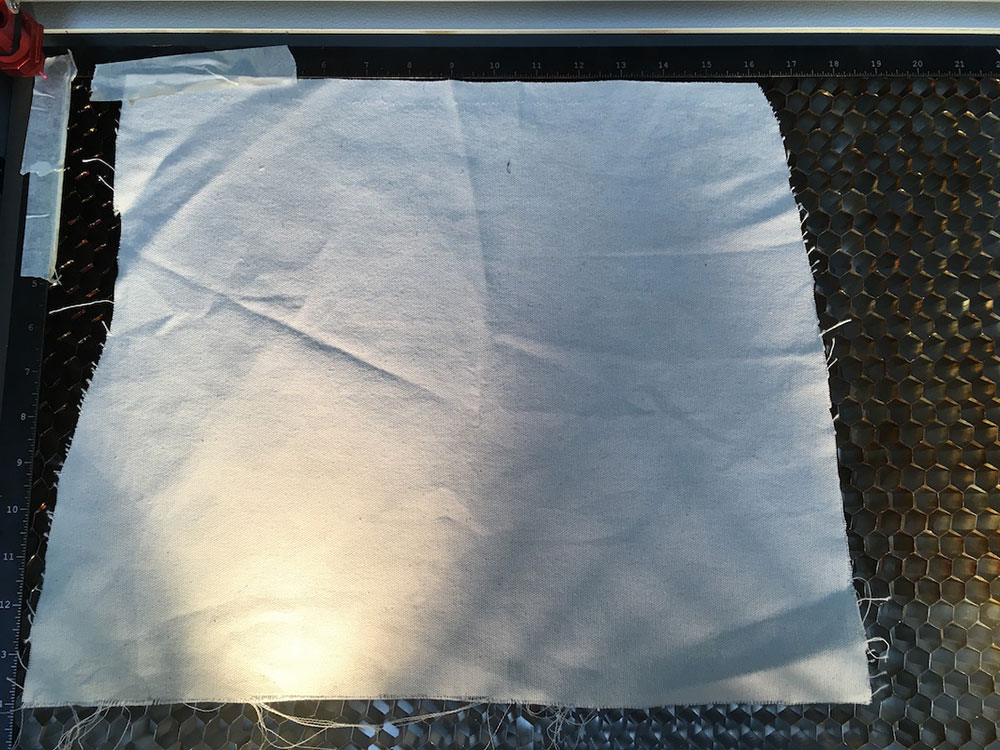
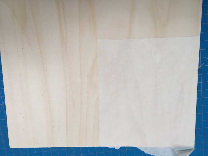
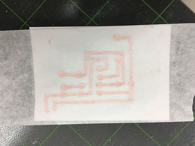
To start I put transfer tape on the plywood. This helps keep the surface clean from the smoke that can stain the surface when cutting.
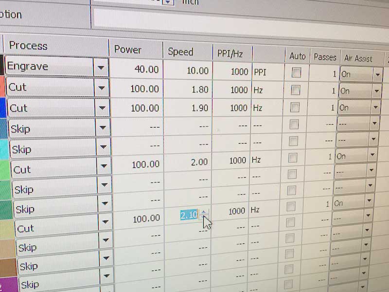
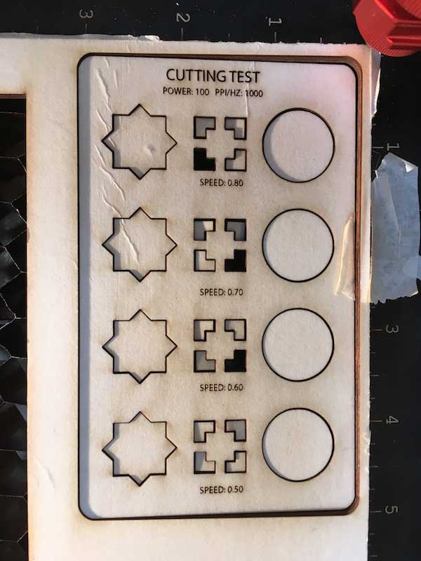
I started by testing the cut settings using close to the ideal parameters I received from my group members for generic plywood and worked backwards from there. Which were:
---> Power 100
---> hz 1000
---> speed .8 - .5
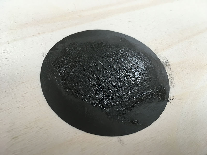
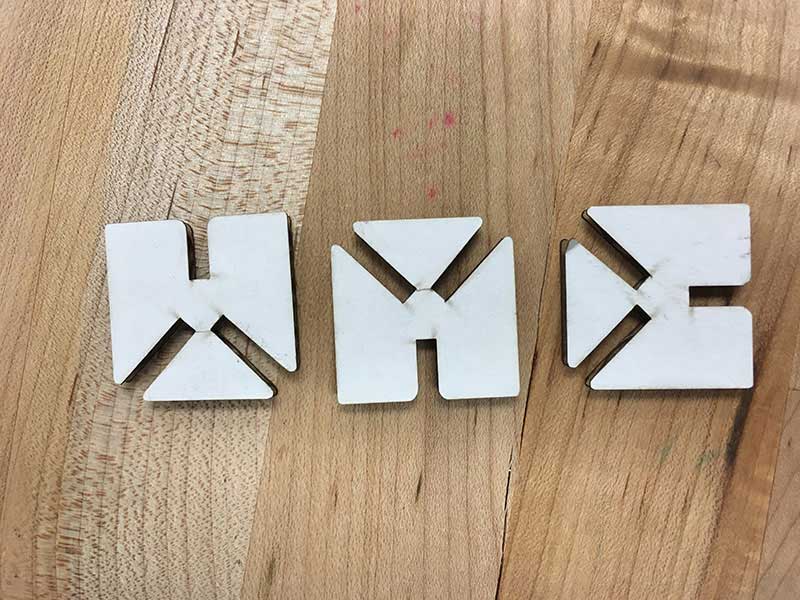
On the surface, they all cut nicely and the transfer tape did the job. So using these settings, .8 speed is ok.
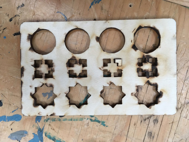
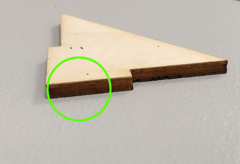
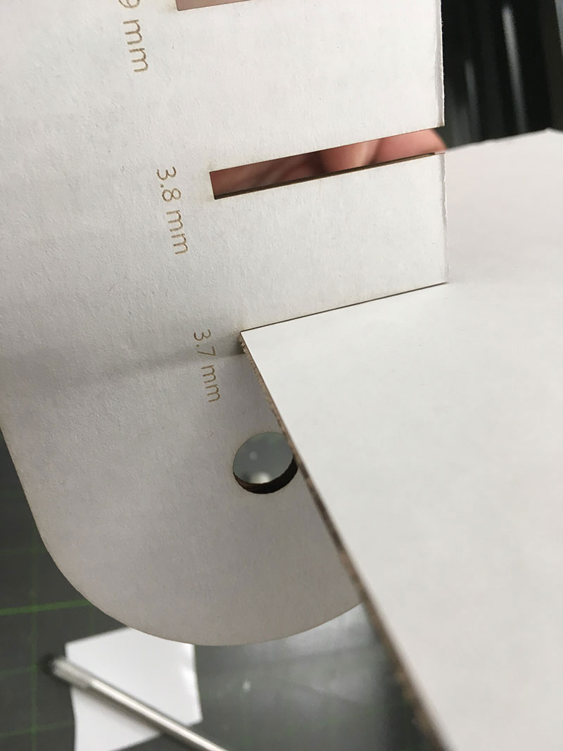
When I flipped the piece over, I could see all kinds of burn marks. This is a result of the laser pushing through the material and having enough force to refract and split off the noneycomb plate burning the underside of the wood. While I could cover the underside with more transfer tape, this is still a sign that the power is too high or the speed is too slow for this material.
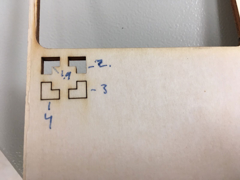
The next test I did was trying different speed settings to find the minimum power/speed required for a clean cut. You can see from my markings, the parts even cut through at a speed setting of 2. This is 1.05 faster than the generic plywood setting from another lab however it rquired a slight push. at 1.8 the material cuts completely through with no push required.
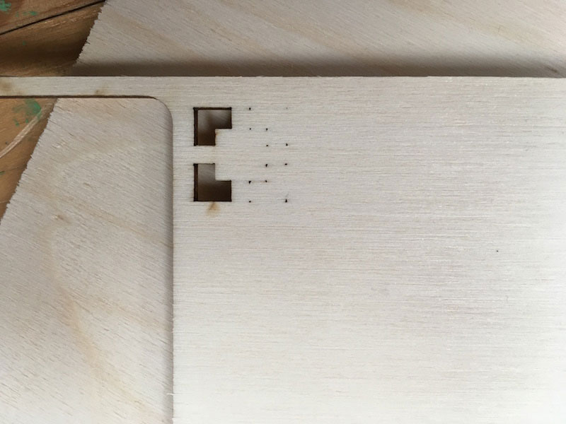
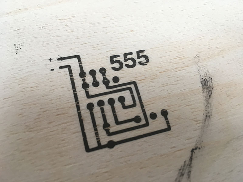
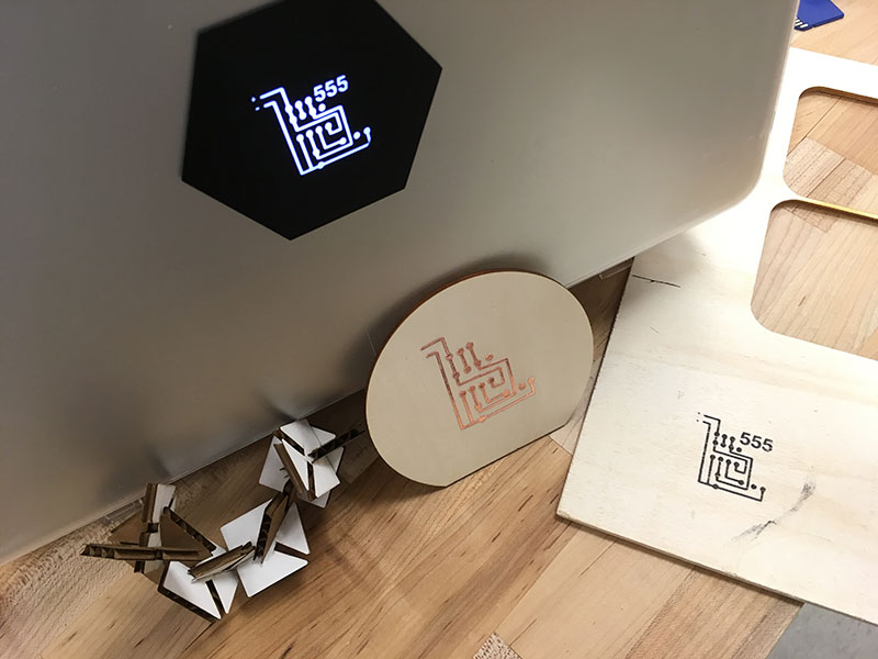
At this setting, I can get a very clean cut. You will notice that the sides of the plywood are not a dark/burnt brown. This particular piece was cut without transfer tape.
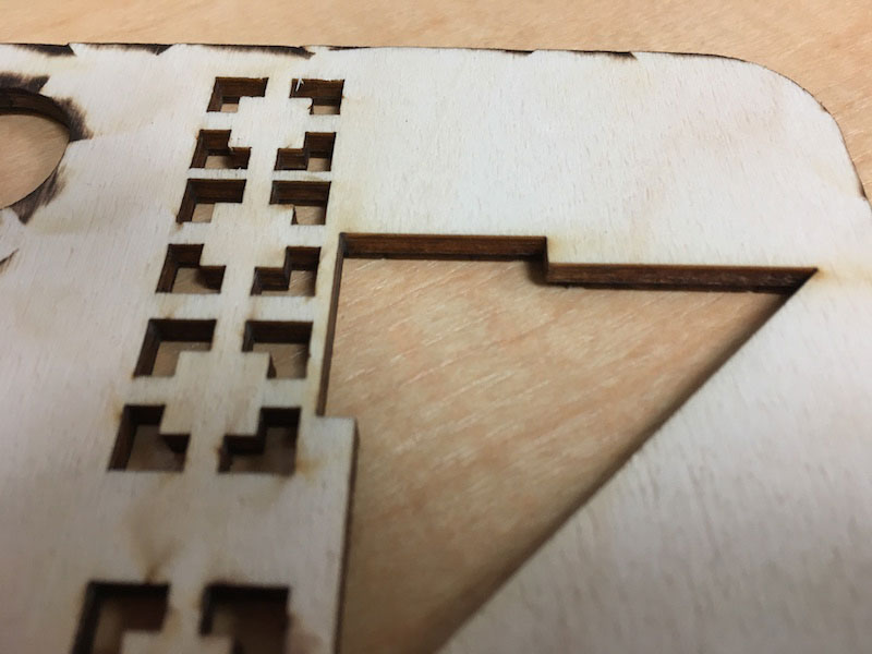
I learned from this test that the difference in settings can be quite large between seemingly similar material. These tests will have to become regular practice in my design process.
Ideal Settings:
---> Power 100
---> hz 1000
---> speed 1.8


