WEEK 8
COMPUTER CONTROLLED MACHINING
ASSIGNMENT DETAILS
Make something big using a large cnc router
POST ASSIGNMENT REVIEW
I had some BIG ideas for this week. We had limited access to the large CNC machine at échoFab DD (échoFab's sustainable design campus). A beautiful lab at the edge of the city. In ordder to keep on track with my assignments I needed to make sure that I completed the project during the visit. I began by prepping some ideas and doing some tests. In practice, my initial idea required more troubleshooting than I had time so I had to adapt quickly in order to stay on track.
INITIAL TESTS
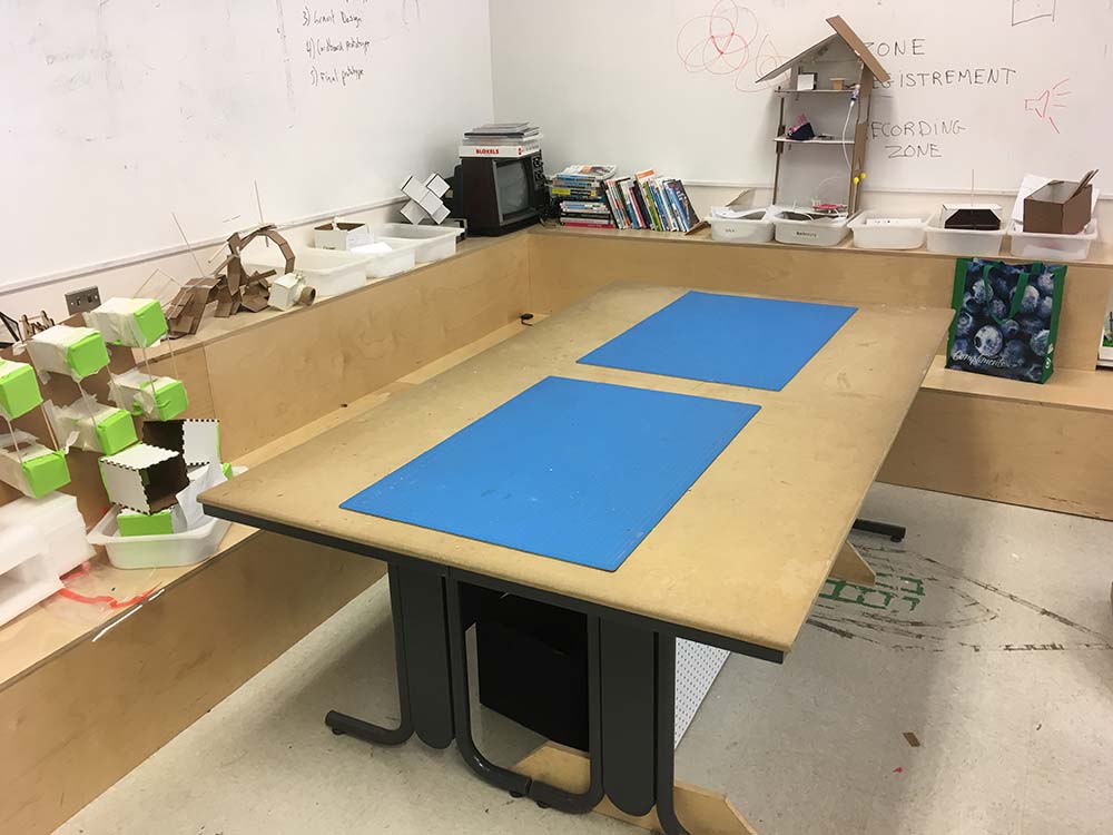
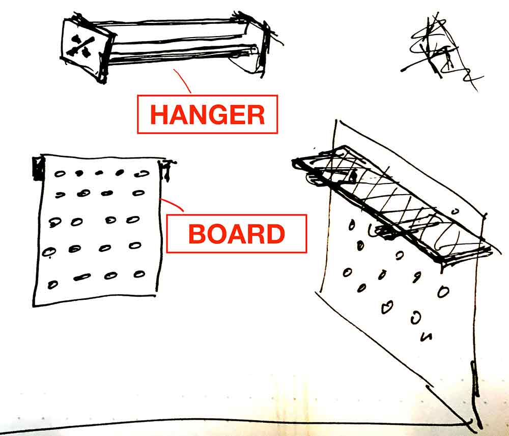
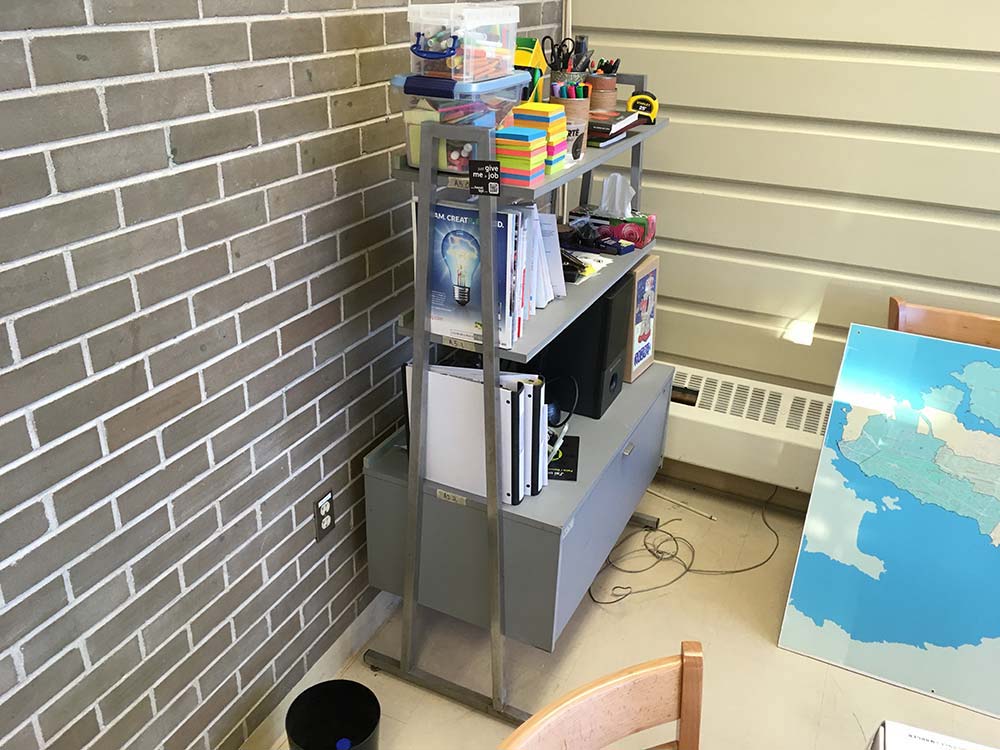
The classroom where I work needs a lot more storage space to deal with growing student activity. My idea for this week was to create a system that could be used to make a variety of storage solutions. Here is a view of a large worktable with projects being stored all over the place next to a sketch of some ideas.
---> first test
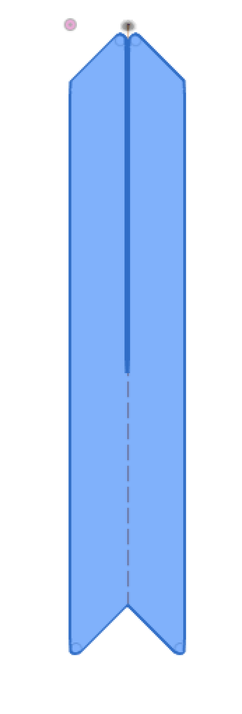
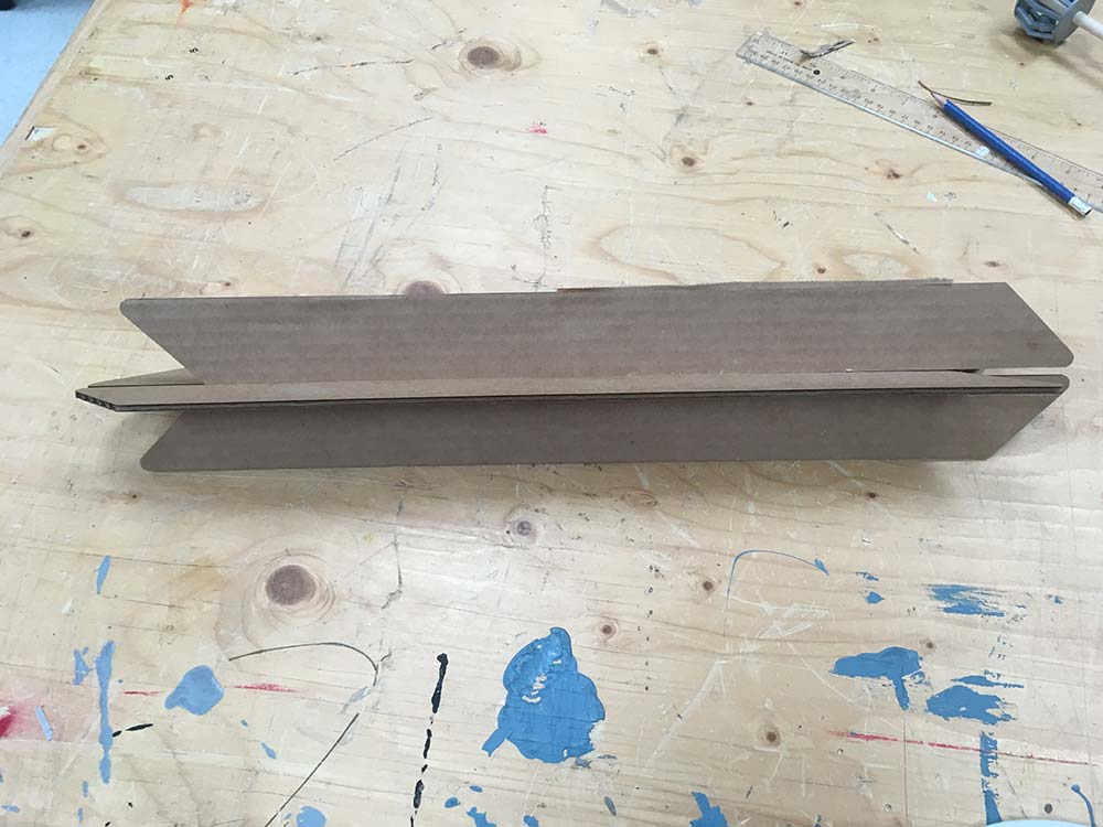
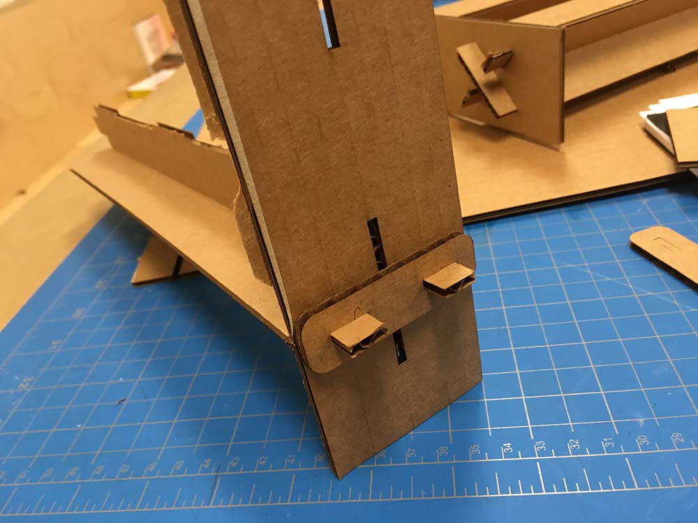
My first idea was to create press-fit bracket system. By combinining two long narrow pieces of wood you could create a fairly strong support beam. I tested the idea with cardboard at first. I thought that by making one end pointy I could maybe make it so that it coulbe be nested into some kind of socket but I dropped this idea pretty quickly.
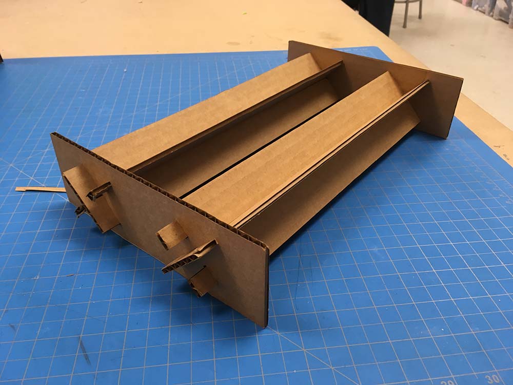
---> second test
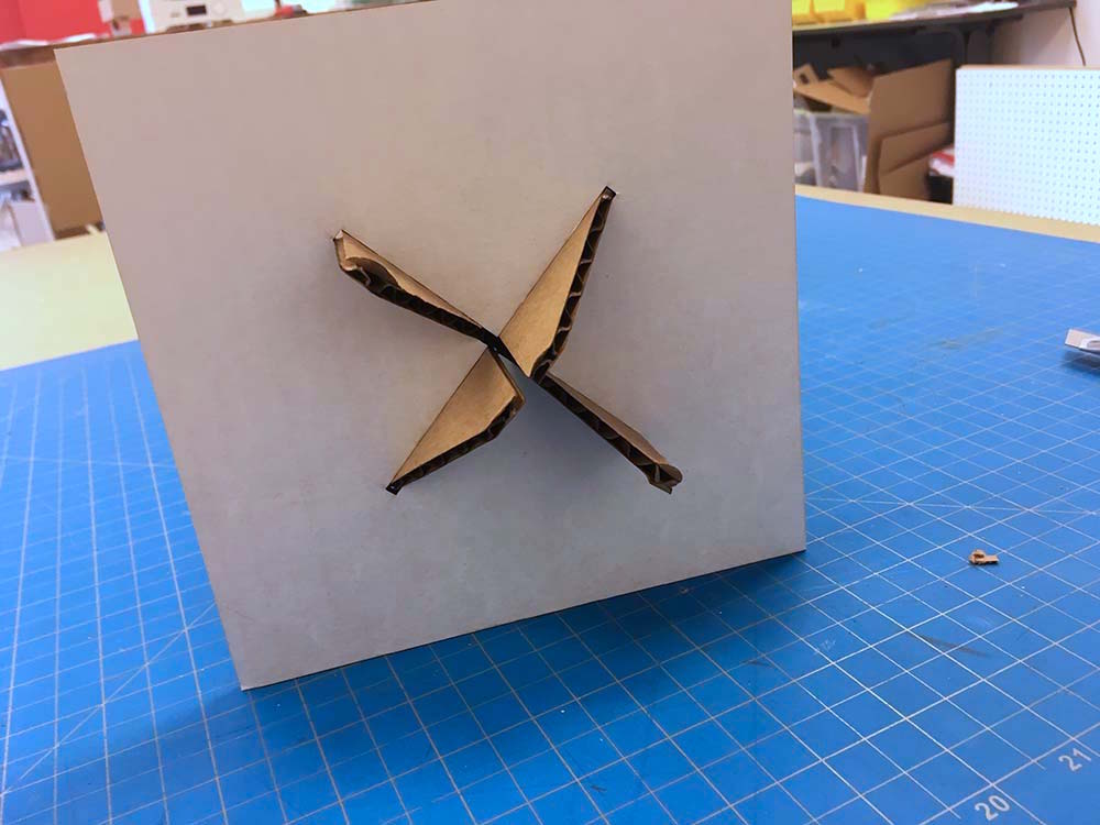
I moved towards more of a wedge style system. My initial tests showed that even with cardboard you could get a very stable brace. My goal was to push the ends of the wood through and then use a smaller piece to wedge it even further. I miss-calculated my spacing and the wedge did not fit which is why you don't see it in the following images. However, there was still enough friction from the press-fit alone to create a fairly stable brace.
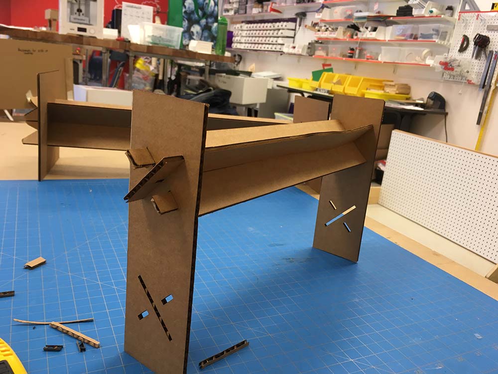
I tried one more system whereby I use an end-cap on the pieces that stick out from the x-braces. In the end I felt it was just not necessary.
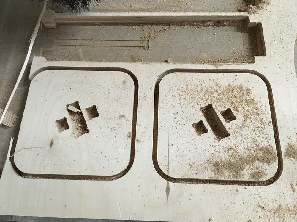
---> dogbone test
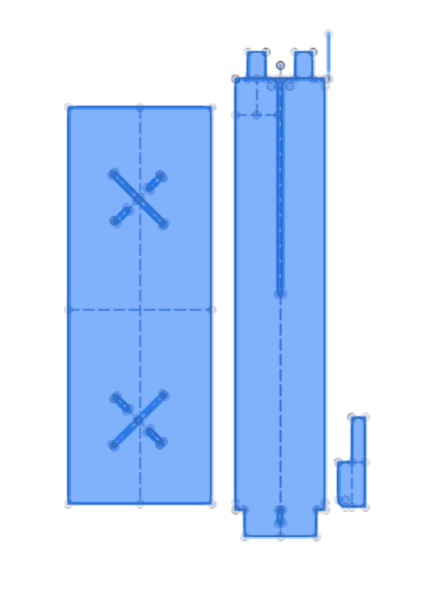
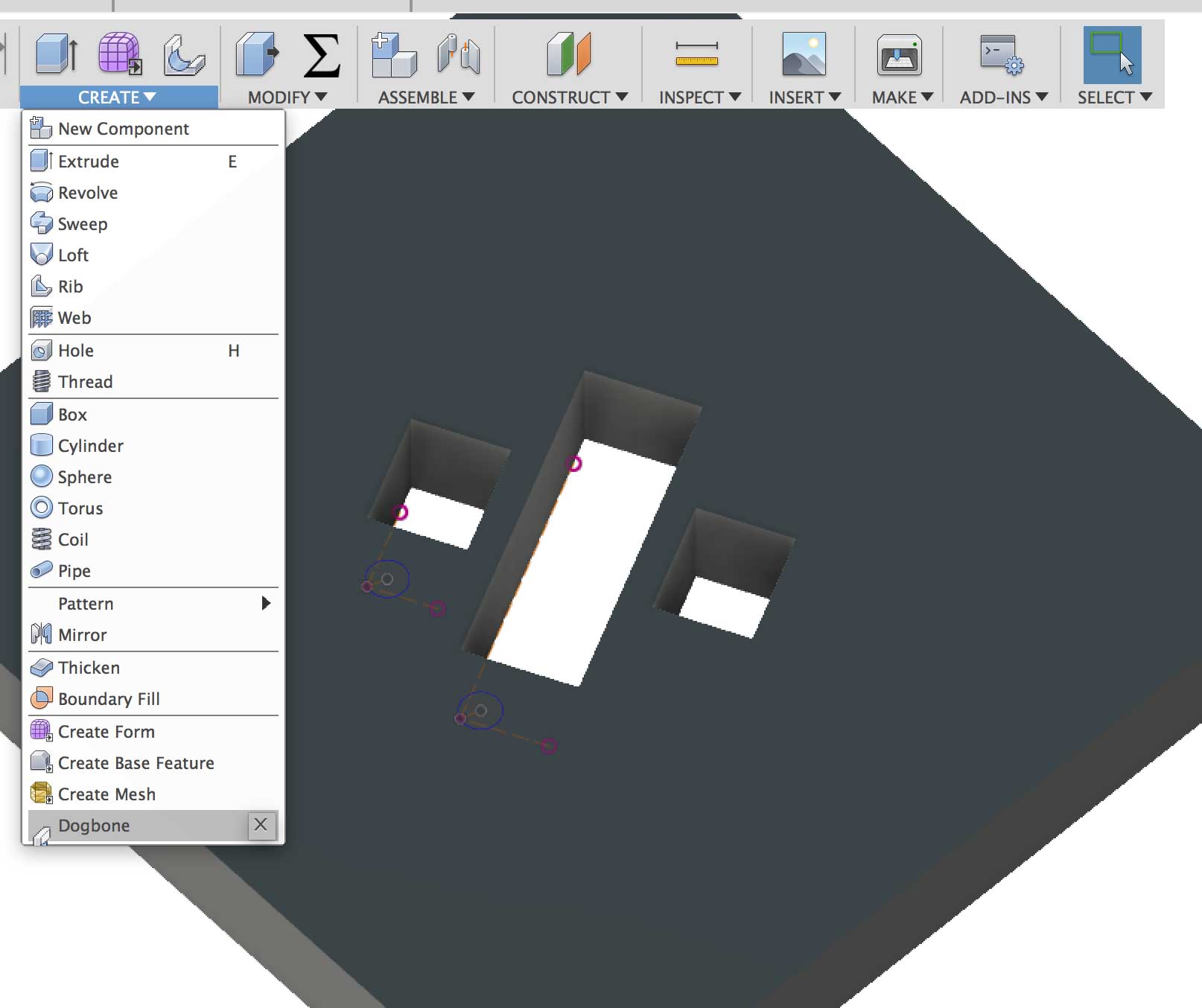
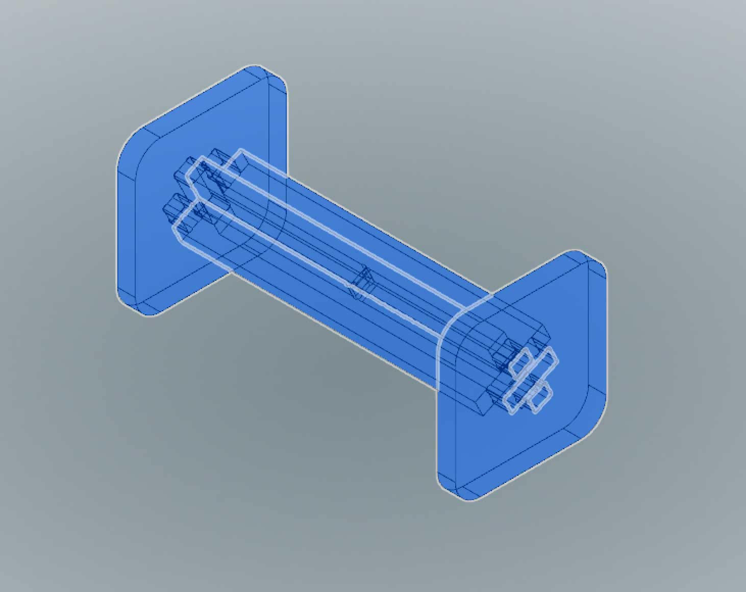
Time management started become a real concern so I stopped experimenting and moved on. I settled on the x-brace system but needed to add dogbone features in the joints. I first created my parametric sketches in Fusion360. My sketches still look like a mess of constraints but they work. I extruded bodies the same "MaterialThickness" parameter that I created for the width of the tabs and notches.
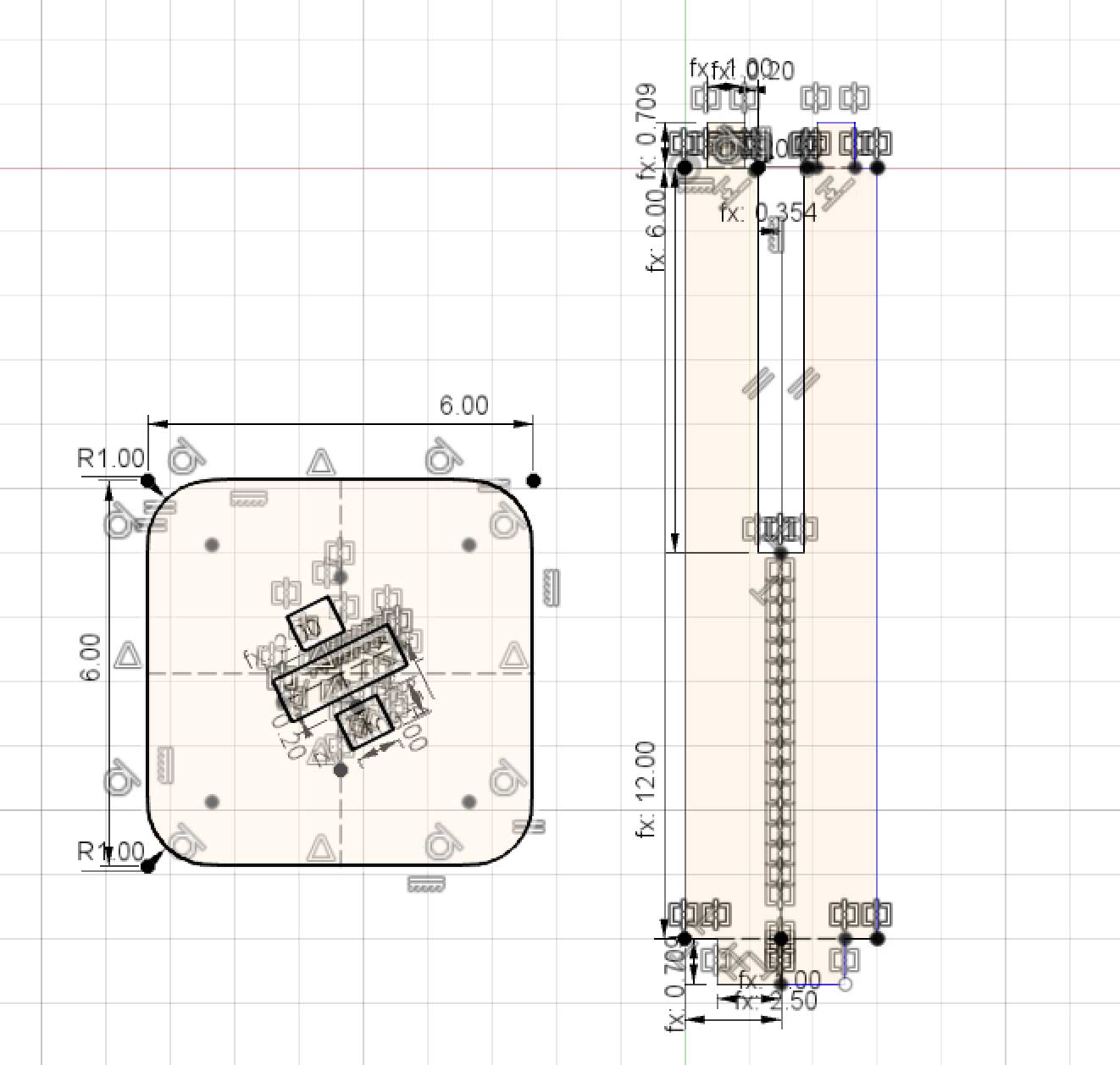
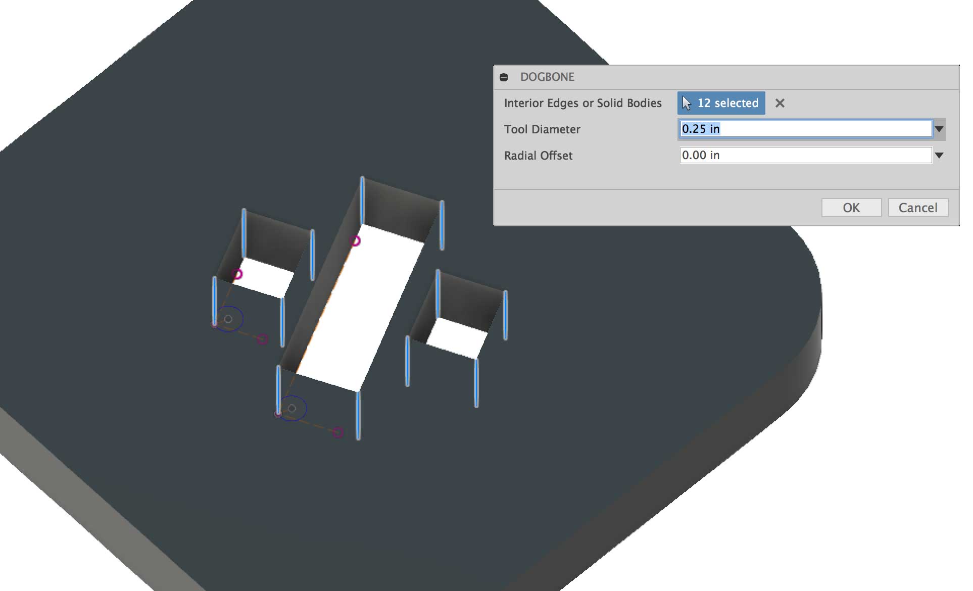
Before creating dogbones, you need to add the dogbone Fusio 360 addin which can be found HERE. Once added, you can find it under the Create Menu. I set the bit size to 1/4" selected the interior edges where I wanted the effect applied and I left the radial offset to 0.
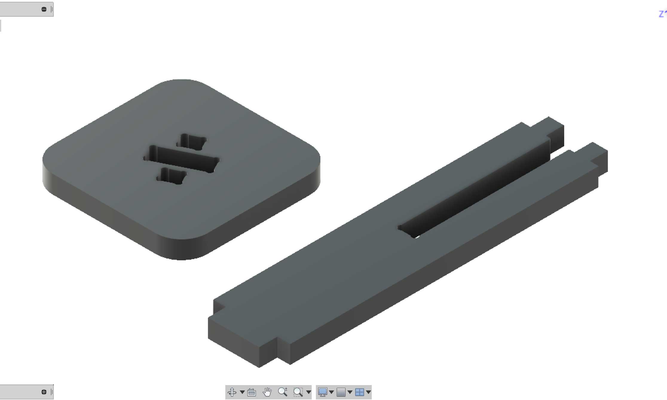
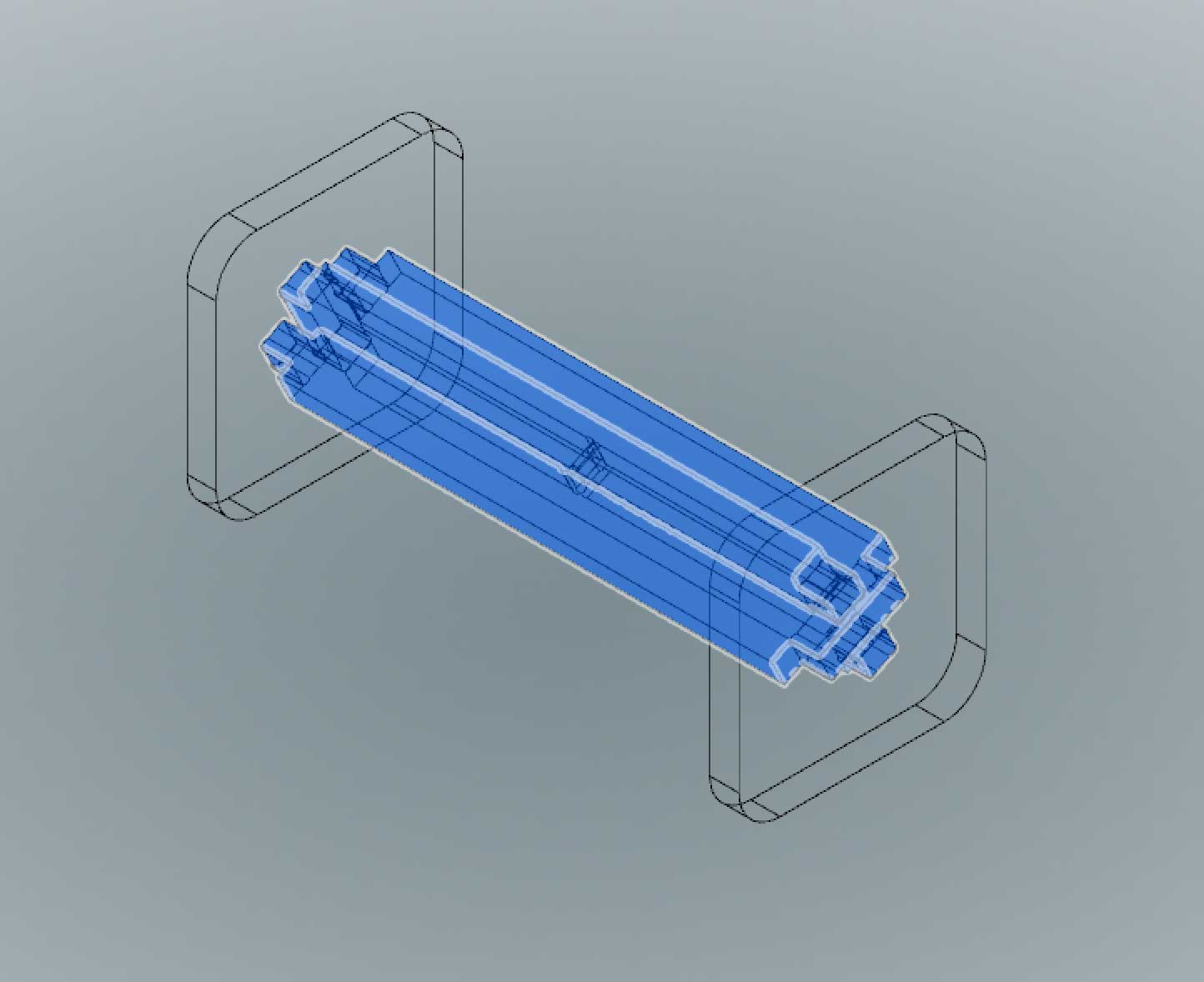
I converted the bodies into components made duplicates and joined them together to evaluate the fit.
---> exporting drawing
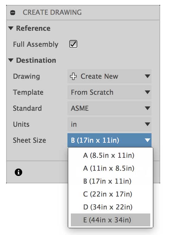
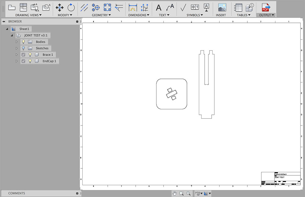
After the design was complete, I create a New Drawing / From Design.
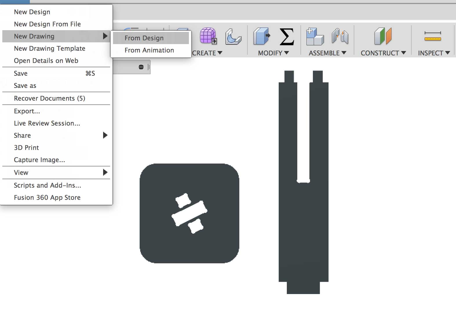
I selected thed largest paper size. In this case it was E(44inx34in)
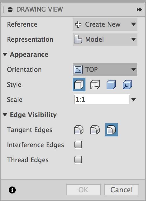
Once in the Fusion 360's Drawing mode you need to select your orientation and scale. Because the sketches and bodies were created along the x/y plane I selected TOP as my orientation and made sure the parts were at a 1:1 scale. For bigger furniture you need to remember the scale factor of your drawing.
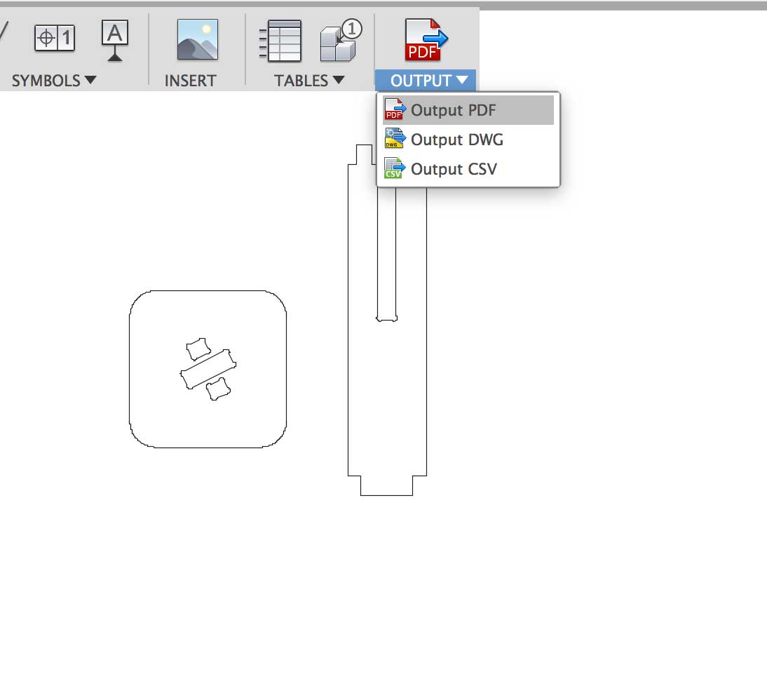
Once the drawing is complete I exported it as a PDF. You can delete the rulers and the reference guide because these will not be needed.
---> preparing the vector drawing
The next step is a familiar one. Importing the PDF that was created in Fusion 360 and into Adobe Illustrator before sending this to the machine software. I would not bother documenting this step but I keep getting this issue which hopefully someone can instruct me on. I have yet to find an answer. When working with drawings, DXF, or PDF, that are generated from Fusion, my fillets are never attached to the rest of the path. For processes like laser cutting and machining, this could result in inefficient processing from the broken path.
To fix this, I needed to join all the broken paths. An annoying step. Hopefully, I will find the solution to this soon.
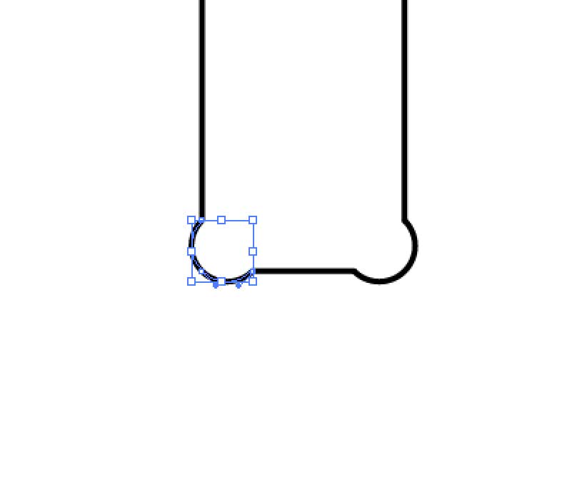
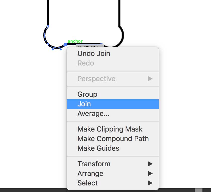
Once reconnected, I have one clean path.
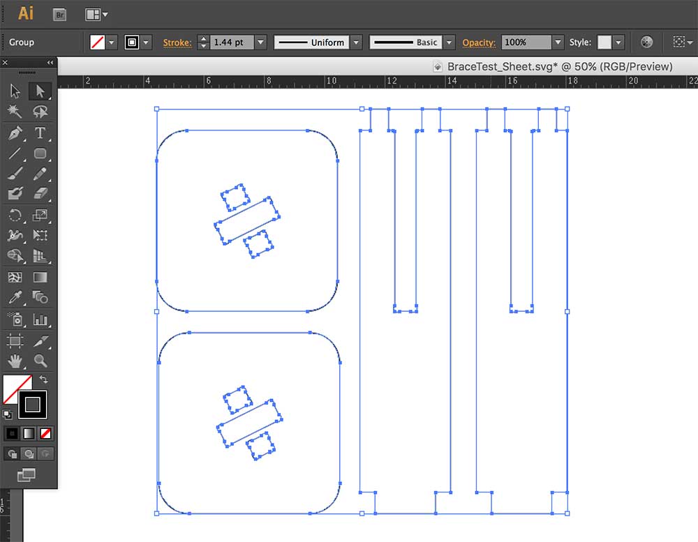
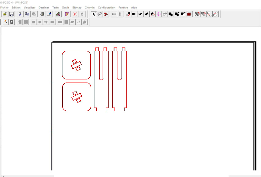
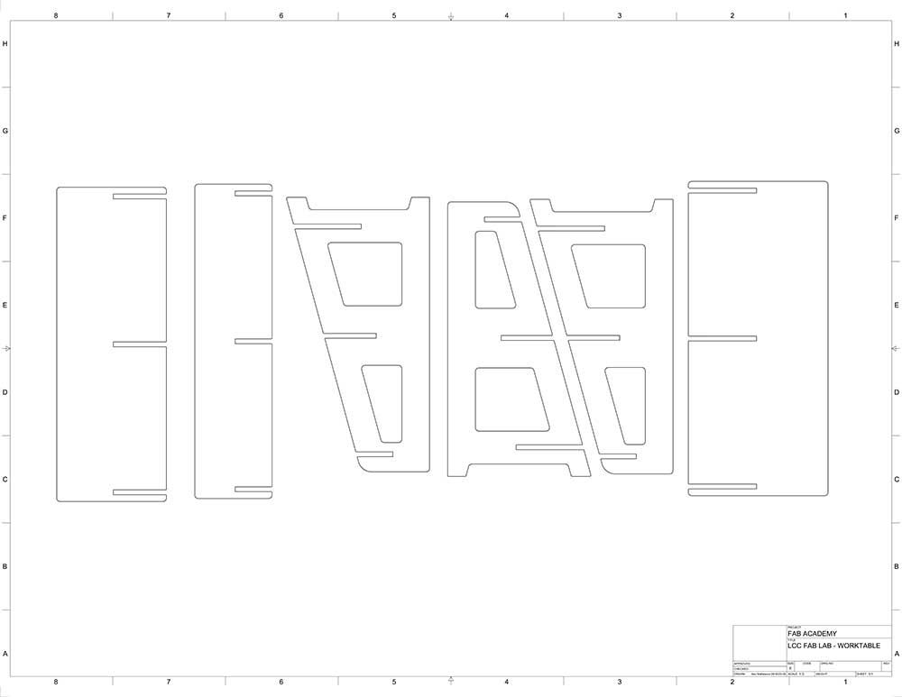
I duplicated the parts I needed and grouped the image. Here is the final drawing ready to be machined.
CNC MACHINING
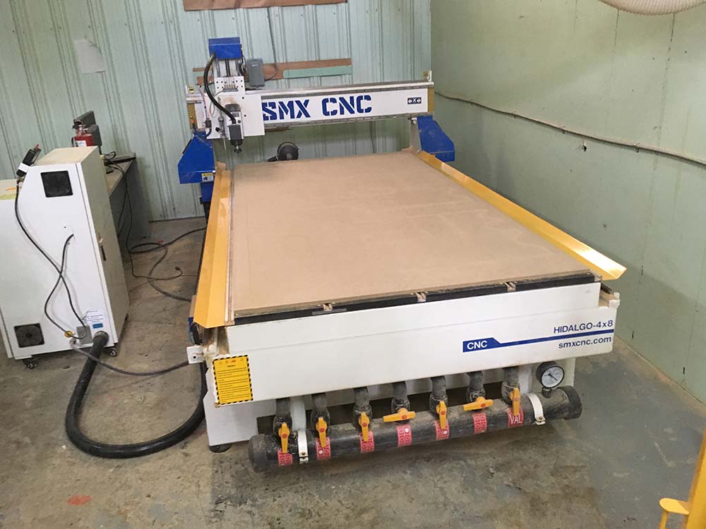
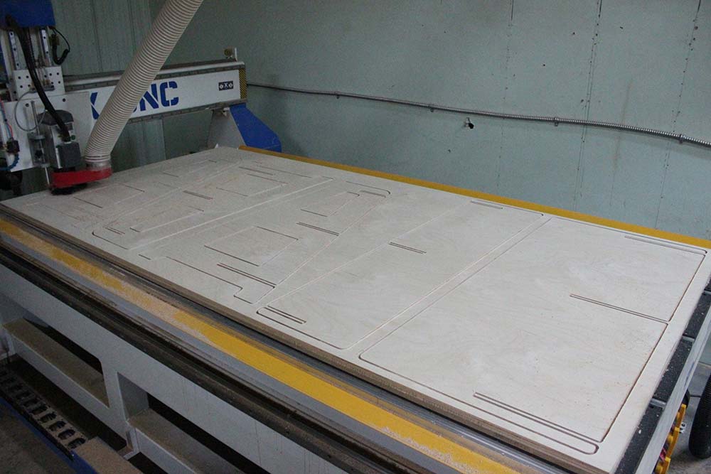
échoFab has a large 4'x8' SMX CNC machine with a vacuum bed. This thing is a beast!.
---> setting up the CAM software
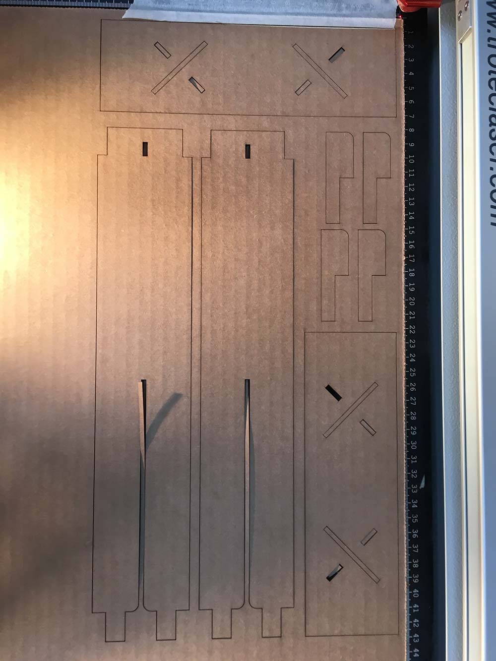
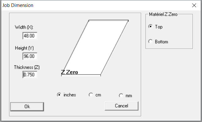
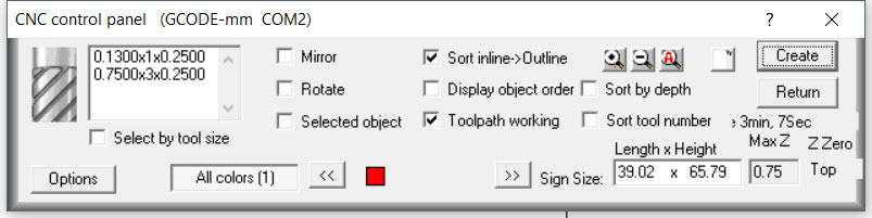
To run it we used a CAM software called WinPCSign. First we set the dimension of the material we were using. I was able to place my dogbone test onto the corner of one of the jobs that was being done before me. We were using an entire sheet of 3/4", 4'x8', sheet of birch plywood. So we first set this into the CAM software.
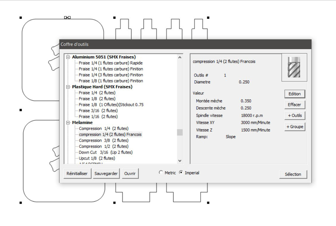
Once the drawing is imported, we needed to select the bit and feed and speed settings. We used a 1/4" 2 flute compression bit. François at èchoFab had already a decent preset for this bit.
---> feed rate (x,y) - 3000 mm/minute
---> plunge rate (z) - 1500 mm/minute
---> 18000 r.p.m.
---> slope style ramp
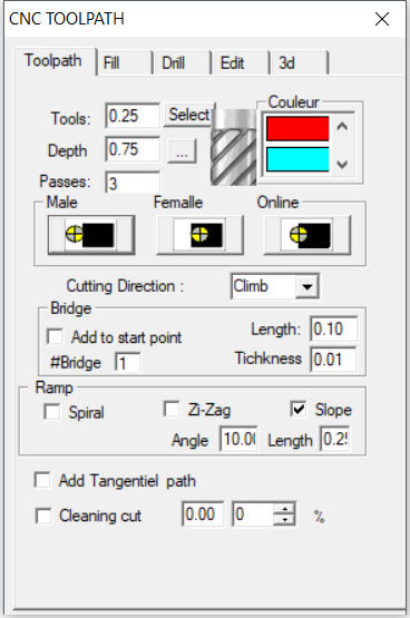
Once the bit is selected we need to generate a tool path. For the outer lines we need to make sure the bit is on the outside of the path (Male). For inner lines, like pockets and tabs, we need to cut on the inside of the path(Female).
---> tool - 0.25"
---> depth - 0.75"
---> number of passes - 3
We look at the tool path, outlined in red and make sure that it looks right.
Once completed we generate the gcoe and save it to a USB key which is then loaded onto the machine.
---> praparing the machine
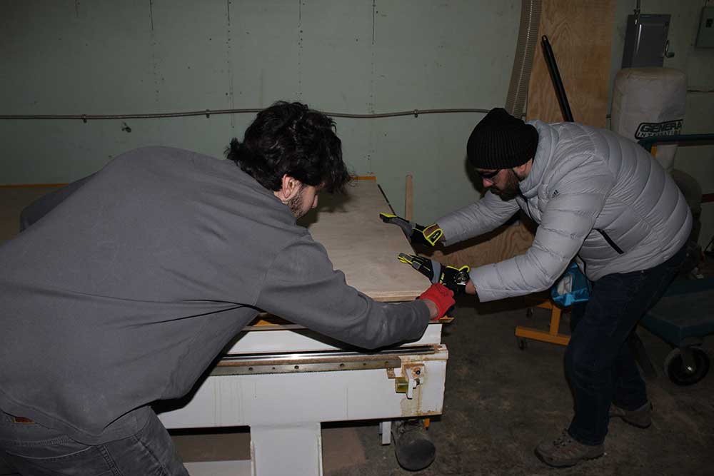
It took a couple people to position the large sheets of wood on the machine bed. Once this is done we then turned on the vacuum.
I did not know this but the vacuum table is strong enough to suck air through MDF without needing any perforations or holes.
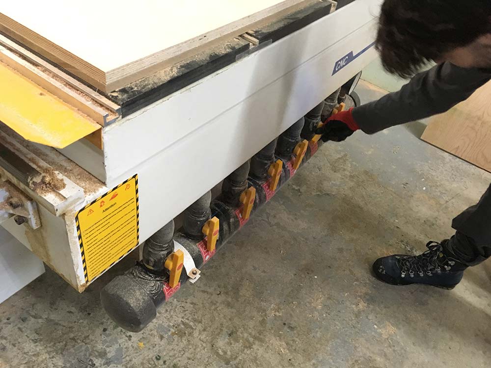
The vacuum pressure was around 0.003 MPa (Megapascal) which is equivalent to 4.35 PSA (pound-force per square inch) for each of the 4 zones.

Once completed, we needed to home the machine. To do this we used the remote to move the router head to the top corner of the material and set the x, y, axes to zero. Then we placed a small puck that the bit would probe and set the z axis to zero.
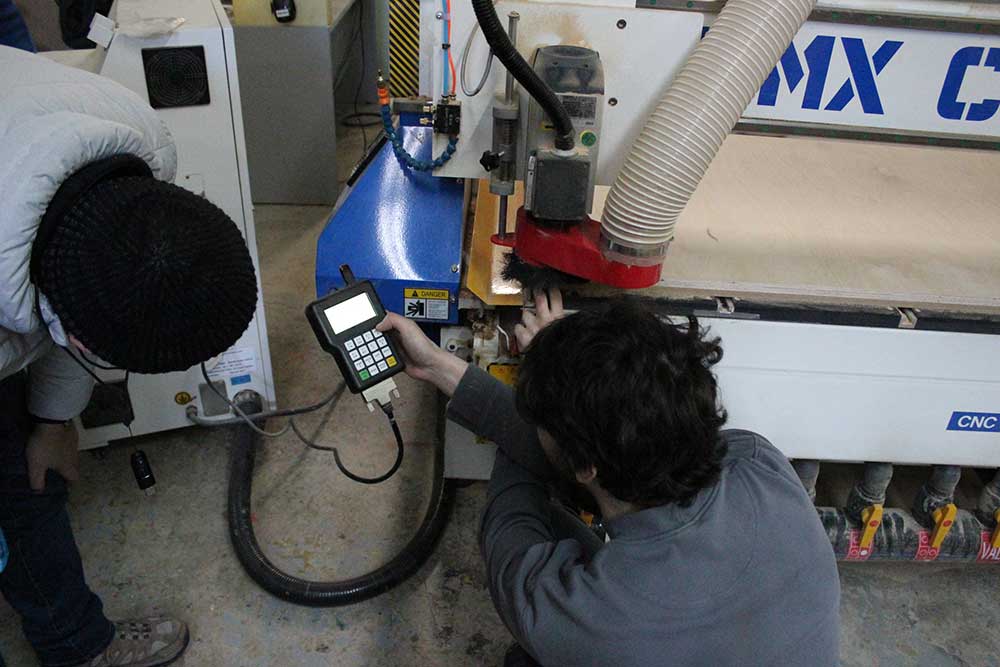
Using the remote, we set teh machine to read our GCODE file and pressed send. Unfortunately, the machine behaved exactly as it should but my measurements were off and the notches didn't fit. Back to the drawing board and to check over my files.
One note is that we did not use a pocket clearing path for the small notches. The compression bit is not good in this scenario. We should have used an upcut bit to help remove the material and done a pocket clearing. It was safe and we kept a close eye on it but perhaps not an idea process for this type of cut as it generates a lot of heat and there is little room for the sawdust to escape. Oh...and that vacuum table is amazing!
SHELF DESIGN
Time was really running out on me. In order to continue with my initial plan I would have needed much more time to develop it. It became clear that I needed to design something big to that was simpler. I decided to do something similar to what my peer George Hanna was doing for his assignment.

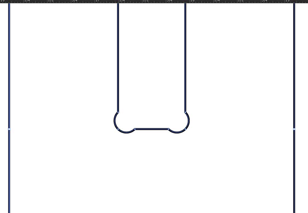
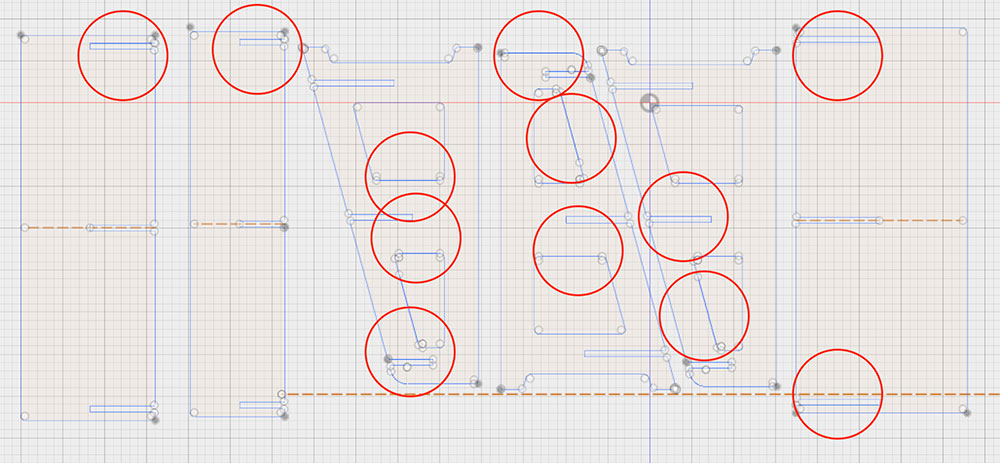
So I designed a parametric press-fit shelf too. It seemed easy enough to pull off in the remaining hours I had before François, the machine operator who was helping us, had to leave. Having rushed the drawing a bit, I did not notice until generating my PDF that there were a lot of duplicated lines. The image below highlights all the areas where there were double lines. These had to be removed. Also, like last time, anything with a fillet (which is important in making press-fit) had broken lines.
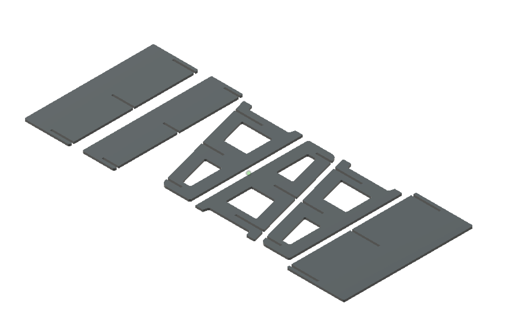
Here are the extruded parts.
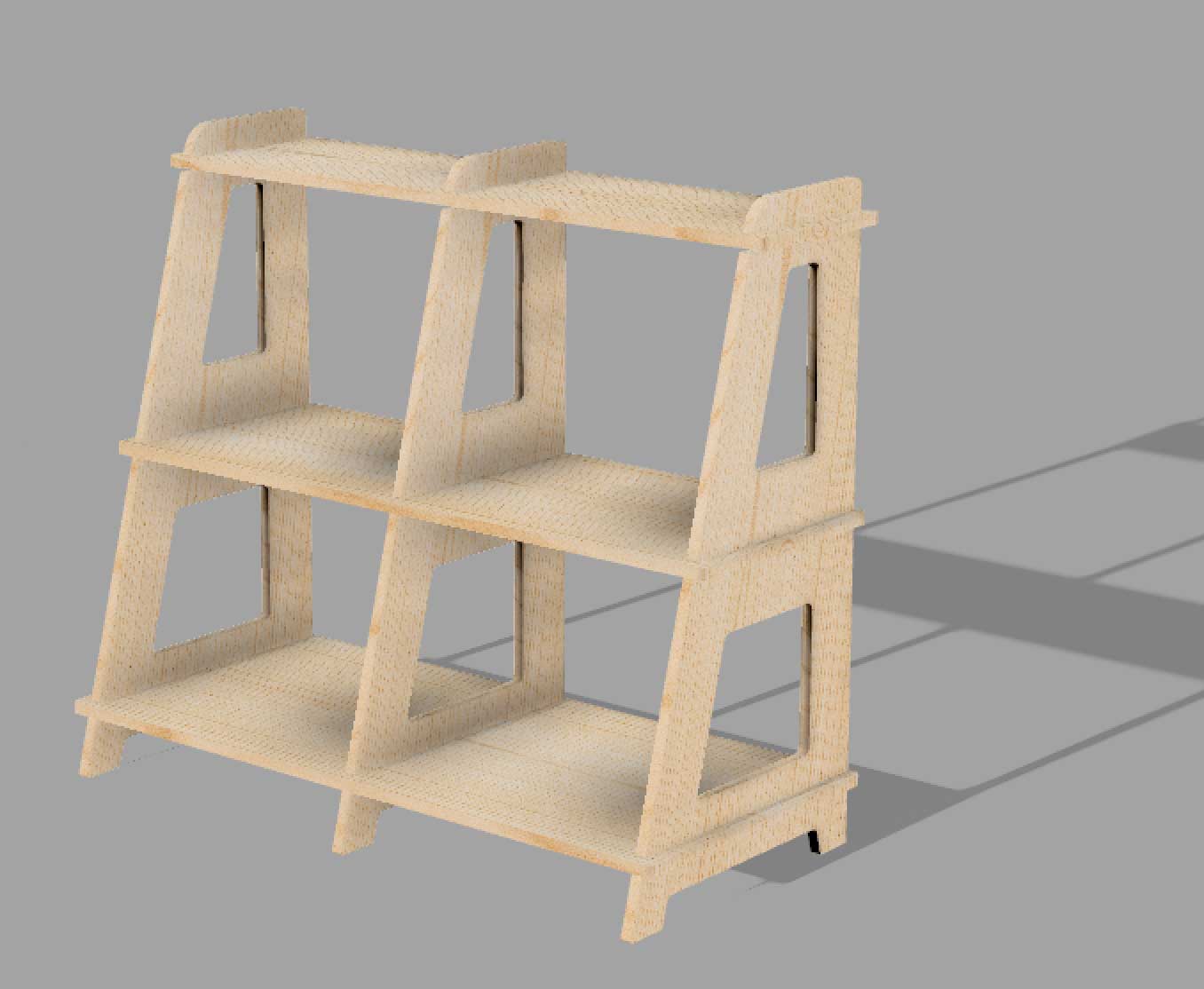
Here is a rendering of the shelf.
---> machining the shelf
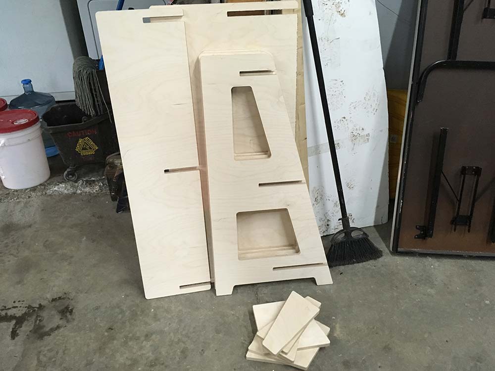
I followed the exact same process for this shelf as I did in the above dogbone test. When ready, I had to clean up the table and helped to remove the previous job.
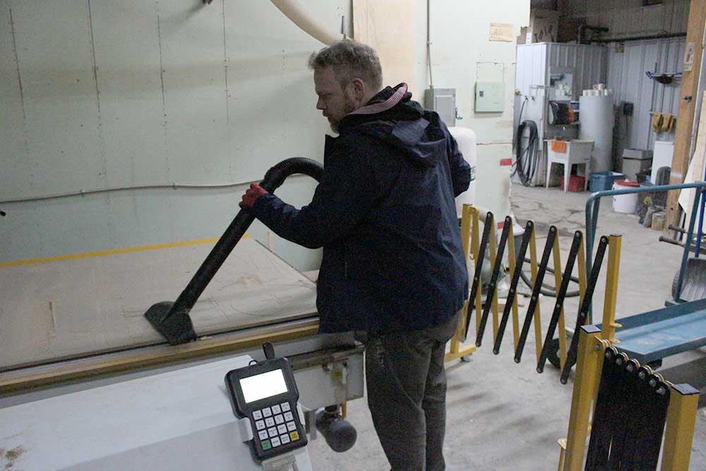
90% of the design fit on one 4'x8' sheet of wood. Luckily, I was able to place one of my shelves on another job that was following mine. If I ever re-design this shelf, I will make it fit on one sheet exactly.
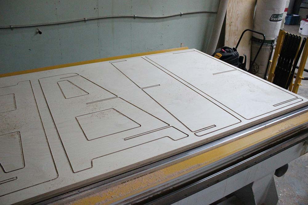
Machinining the pieces was a breeze. The settings were perfect and it was the perfect job for the compression bit.
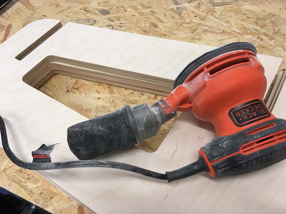
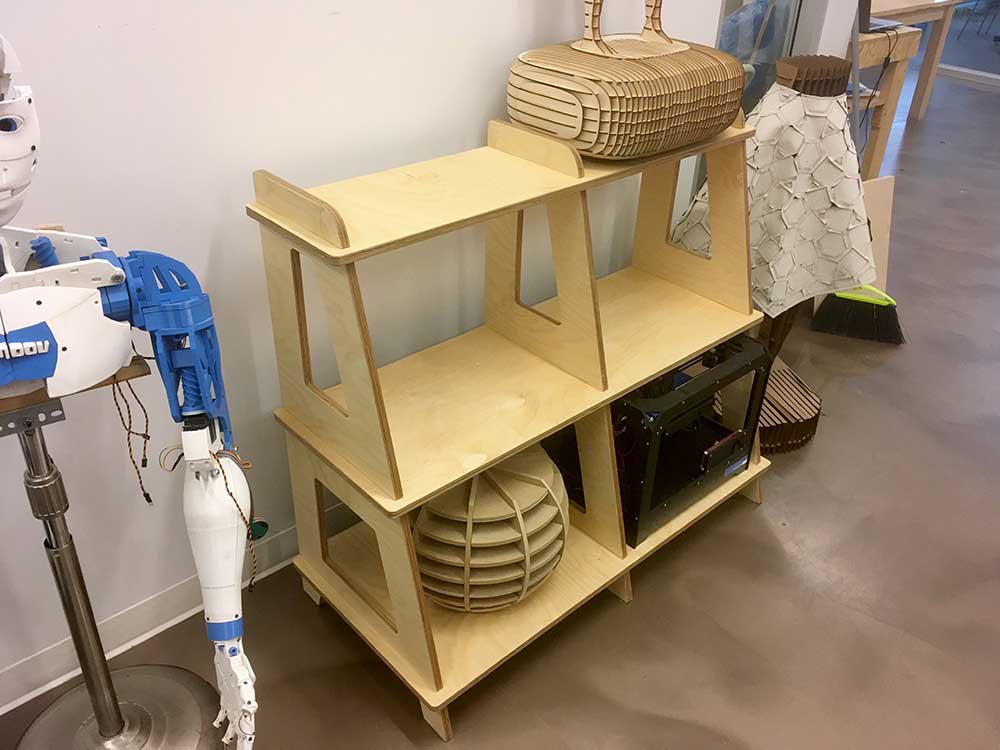
---> assembling the shelf
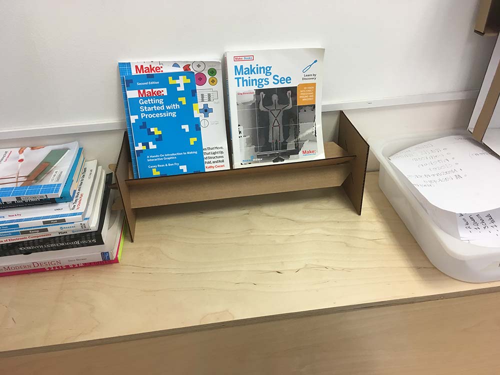
Finishing the shelf took a bit of muscle. I sanded all the pieces and needed to hammer the shelves into place. I dusted off the sand and rubbed cutting board oil over the wood. In the end it looked pretty good and was definitely sturdy.
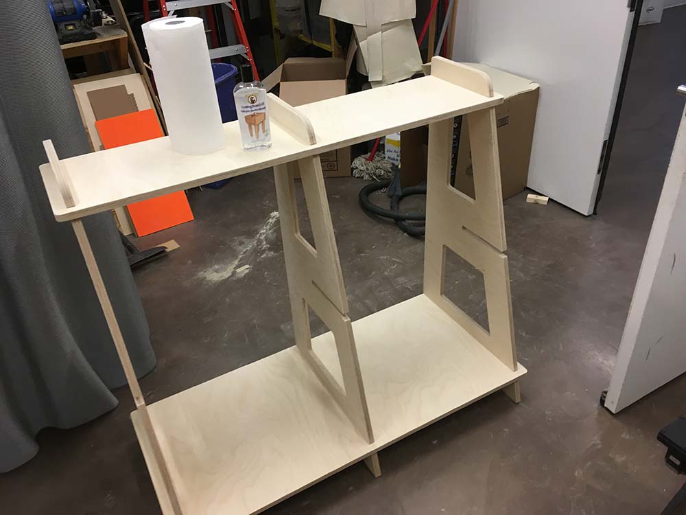
Our instructor Mathieu asked if I would donate it to échoFab. I made a deal that I could go back to work on a new one for my classroom. In the end, I am happy it is being used and on display.
ASSIGNMENT FILES
---> XBrace Design / Dogbone Test - PDF
---> XBrace Design / Dogbone Test - Fusion 360
---> Fab Lab Shelf - Fusion 360
--->
Fab Lab Shelf - A - PDF
--->
Fab Lab Shelf - B - PDF

This work is licensed under a Creative Commons Attribution-NonCommercial-ShareAlike 4.0 International License.