Electronic Design
In terms of electronics, I needed two board for my machine, the first board wich is the brain of the project is essentially an attiny44 receiving an input from a chip named
MSGEQ7 and output the received data to my second boards that will drive my motor using a4988 pololu drivers. The MSGEQ7 is a chip that is used for doing an FTT, it is a multplexer that take an audio signal and store it into 7 frequency window. It is composed of 8 pins, and it's pretty easy to understand how the chip works. let's take a look at our pins and our block diagram.
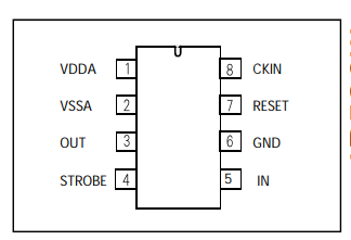
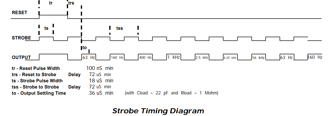
We see here that the board as an input pin, an output pin, a strobe pin and a reset pin, a Clock, a VCC and a ground, these are the pins I want to talk to you about.
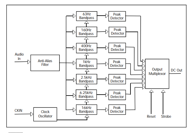
The way that the chip works is that it receive an audio signal from the input pin and output the peak value of each bandpass trough the output pins, the clock then activate the strobe pin and the multiplexer pass to the next band. Once every band has been output, the multiplexer reset via the reset pin and the loop goes on as long as there is an input. The chip only needs a few external components to work as intended, all we need is capacitors for coupling and decoupling uses. This is "grosso-modo" what the chip looks like, it is really fun to play with it and a lot of project were made using it.
For more detail on the chip and it's functionning, please refer to the datasheet that is avaible on the files at the botom of the page!
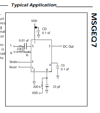
Here is a basic application schematics of what the chips needs to work as intended, this is on what I will based the first part of my circuit design:
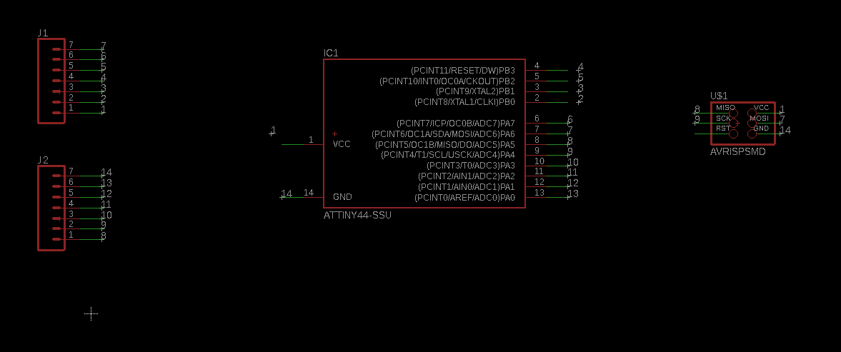
Before designing and milling my final board, I tought it could be a good idea to test my circuitry using a prototype board (bread board) so I could easily work on my design without having to use too much of my time and resources doing pcb's on SMD component over and over again. please bear in mind, this is by far the biggest electronic chalenge I have ever done, so I was not too confident going straigt up for a final board. So first before anything else, I design a simple break-out-board for an attiny44. to do so, I used eagle!
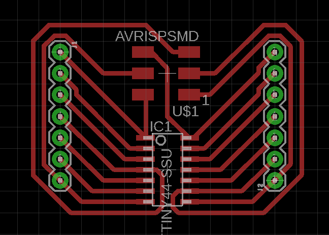
Once my project was created, I opened up a new schematics and insert the component I would need using the "add" command, in our case, we only need two 7pins trough hole headers, an attiny44 smd and our ISP headers SMD. once everything was put up on my schematics page, I use the "net" command to make some small tail to each of my component pins, then I used the "name" command to gave each of my headers pins a number from 1 to 14 (14 pins on the attiny44). I then named each of my attiny pins from 1 to 14 using their respective pins order. that linked all my pins togheter and i'm now ready for switching to my board!
To design my board, I couldn't just place the component as I please, I had to place my headers respescting the dimension and pitch of a common breadboard, to do so I went and took a loot of the dimensions of a breadboard.
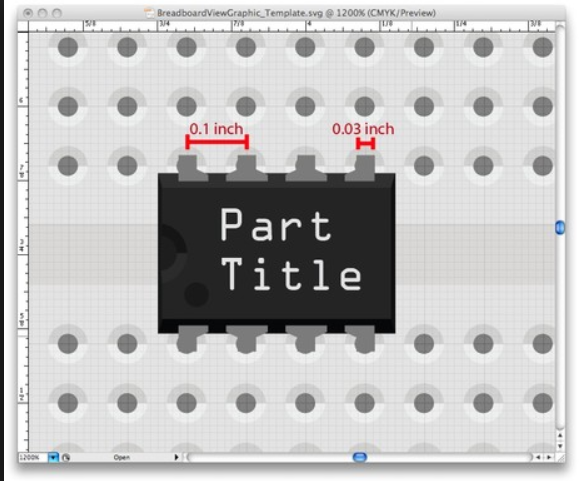
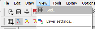
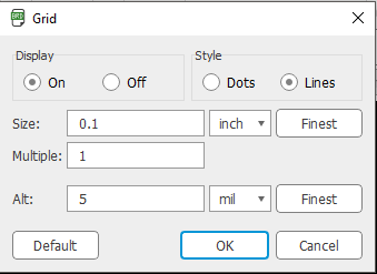
Ok, now that I know that my breadboard has a .1" pitch diameter, I can go into my board panel into eagle and set up a visible grid using .1" spacers:
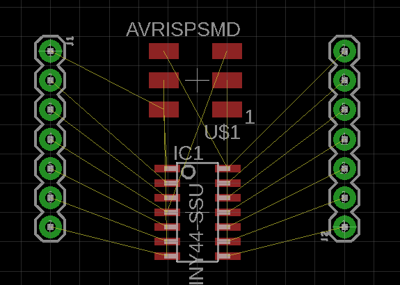
Now that my grid is setup i'm able to place my component without havin to worry if it's gonna fit my breadboard or not. Once the component are placed, you can go and set your DRC tool to get ready for the autorouting command.
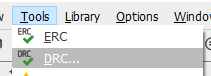
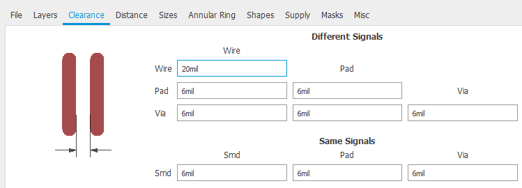
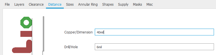
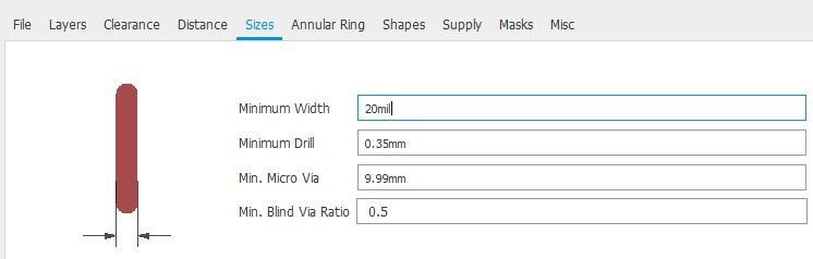
Once the DRC parameters are set, we can go on and start the autorouter tool.
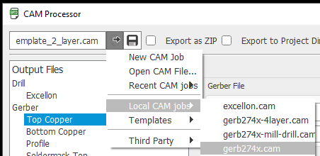
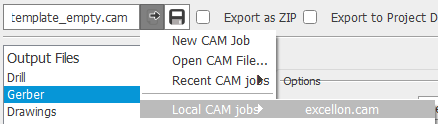
Now that my board is design, we are ready to import it into Flatcam to get our toolpath ready. First thing I did was to go into my "CAM Processor" tab into eagle and process my job as a gerber file and an excellon file:
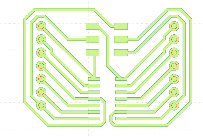
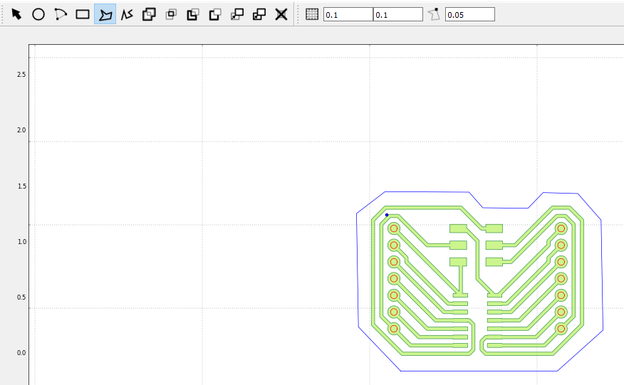
Now that this is done we can go into Flatcam and import our .cmp (gerber) file and our .drd (excellon) file.
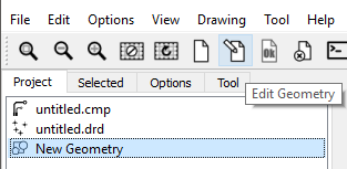
For the outline, we will create a new geometry and edit a polygon in the form of our outline.
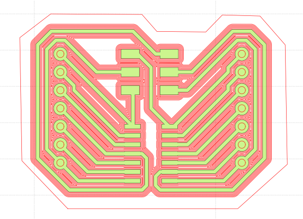
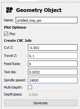
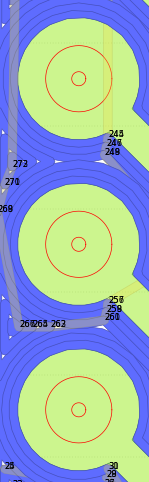
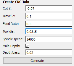
We can now go on and prepare out trace tool path by selecting our gerber file and going into the selected tab, here are my settings:
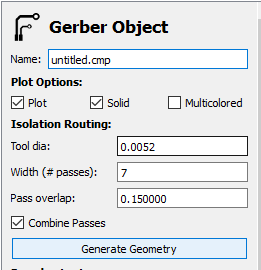
Once this is done, go back into the project tab and select now your newly generated .iso file.
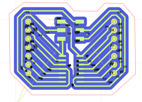
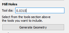
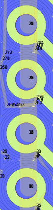
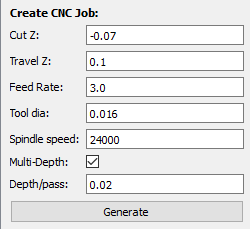
Same process goes for the excellon and outline job:
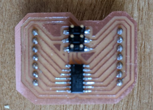
We can now go and export the created gcodes and send it to your machine! My cellphone was out of power when I mill the board, but here are the final result!:
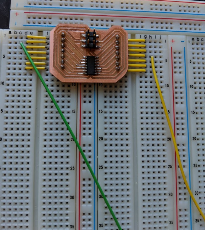
This board will make testing my circuitry on a breadboard before milling my final board possible, this will save me money and time! lets see if it fits on the breadboard.
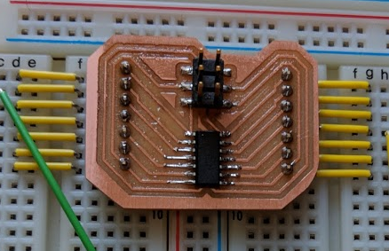
perfect!
Now that this is done, we can go on and think about the what our final board will look like, the circuit we need to build is not super complex, First part of the circuit is the MSGEQ7 part, so I need to redo the exemple circuit they gave on the datasheet.
The 22K resistor after the input are there to limit the peak voltage of my audio signal, this will give result in a smaller range, we aloso see capacitors that goes from the VDD to the ground this is a decupler that limit interference in our circuit.
So what I did is that I reproduce this circuit into a schematics in eagle. To do so we open an empty schematic in eagle and add our component using the "add" comand, then we can link them togheter using the "net" command or by naming them by the same name using the "name" and the "label" command.
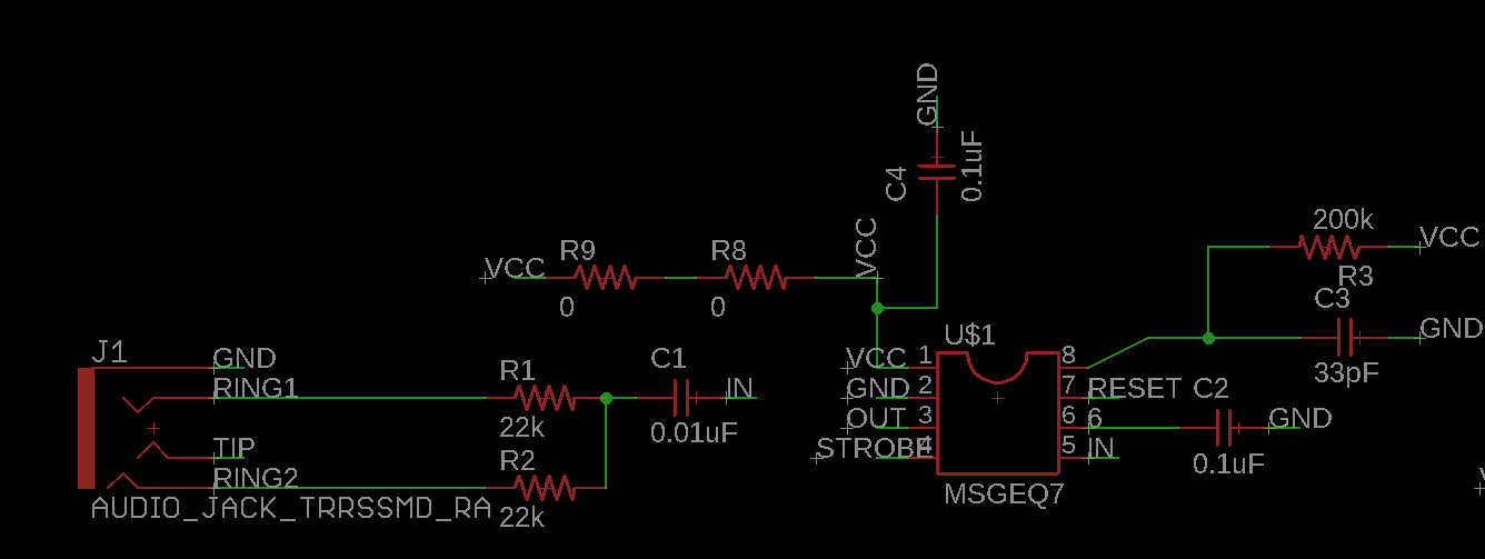
This is the input part of the circuit, It takes an audio signal and the MSGEQ7 process it into 7 frequency windows that will be output via the out pin, but what's next? We will now have to design the rest of the circuit, a simple attiny44 will take the data outputted by the msgeq7, it will process it and then it will send it to my stepper motor using a DRV8825 stepper driver. Since my board already serve as an INPUT and a OUTPUT by receiving information from the MSGEQ7 and process it, transfor it byt my program and output it to my driver, my FabAcademy GURU, Wendy Neale, suggest me to use a commercial board for my stepper. She suggest me the use the Pololu A4988 driver, but since it's current limit was just above my stepper, I decide to go for a safer board a use the
DRV8825 DRV8825 driver by Texas Instrument.
So first of all let's take a look at this driver:
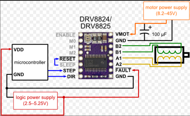
We see a few interesting thing here, first of all we need two source of power, one for the logic (2.5V - 5.25V) and a other one for the Steppers (8.2V - 45V) We will keep that in mind when we will continue to design the second part of our main board, as well as when we are gonna design the breakout board for this driver.
Apart for the logic supply we see that our microcontroller will have to control the step and dir pin. we also use four pins to connect the two coil of our stepper. The rest of the pins won't be useful for us, but we will short the reset and sleep pin like indicated in this schematic. Also we see that theres a decupling capacitor between the VMOT and the GND. So just need to indicate in our code the direction of the motor aand the step it has to do, the driver weill take care of the rest.
This driver can drive up to 2.2 amp per phase, this should be enouph since my steppers use a maximum of 1.7 amp per phase, should be good!
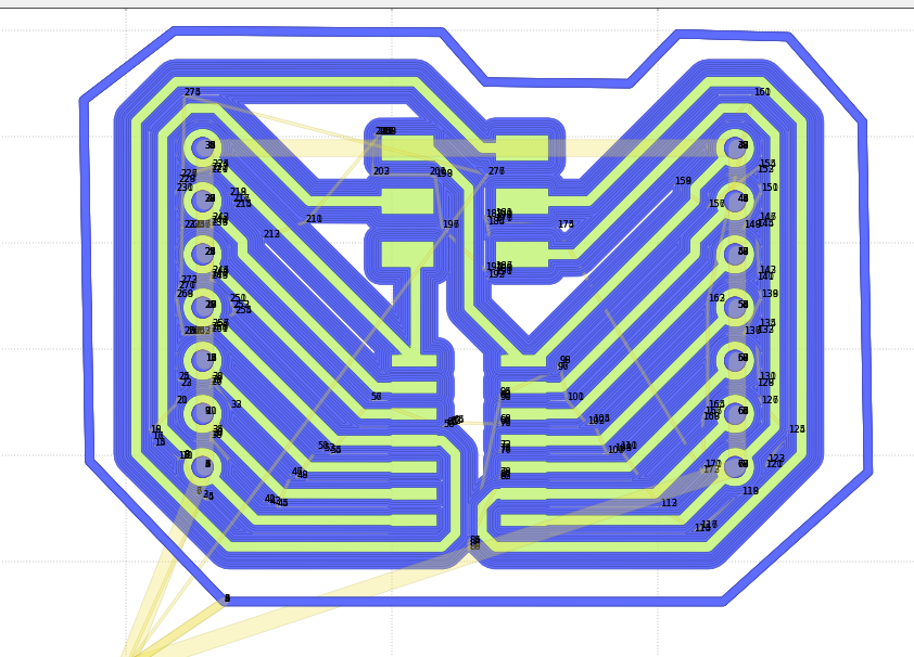
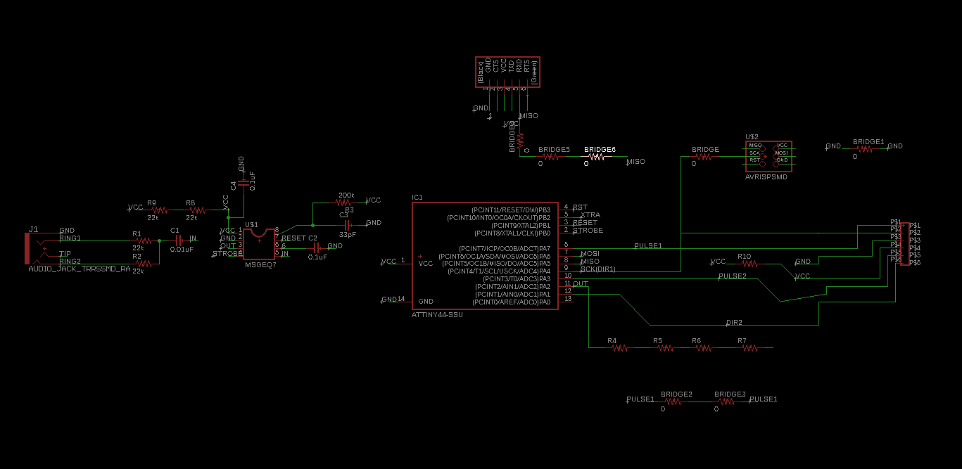
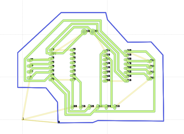
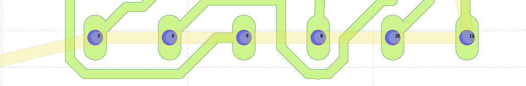
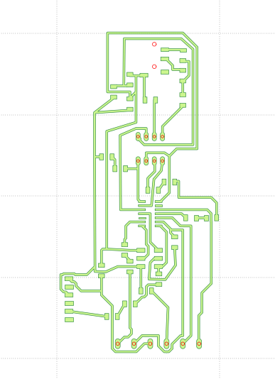
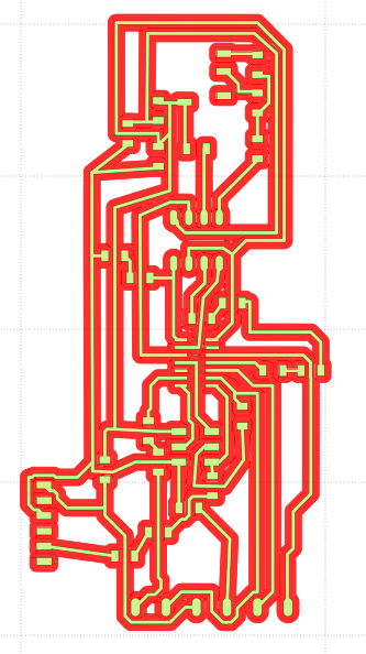
Allright, so lets design the second part of our board, go back into eagle and add the rest of the component, All I really need to add is an Attiny44, a isp header for programming the board, a 6 pin via to output my vcc, ground, step (x2), and dir(x2) to my second board, and a FTDI header for reading our serial data for diagnosis and for supplying the board and the driver it's 5v voltage, I also had to add a BUNCH of 0ohm resistor to bridge my trace around the circuit since i'm only doing a one layer board.
As usual we do this by using the "add" command and we link them using the "net" command or by using the "name" and "label" command:
Now that this is done I can already go into the board tab, set my DRC tool, place my component a start the autorouter tool:
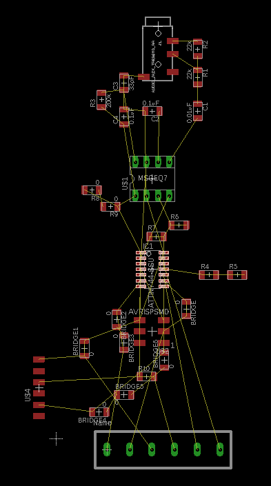
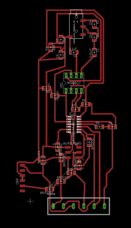
You will have to play around with the bridges to fit everything nicely.
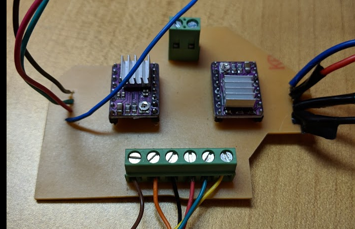
Allright Now that this board is designed we can go on and design the breakout board for our drivers. Using the same process as Always, I went and draw my schematics, this is really just a break-out board for the use of two DRV8825, I use the same supply and GDN for both of my drivers:
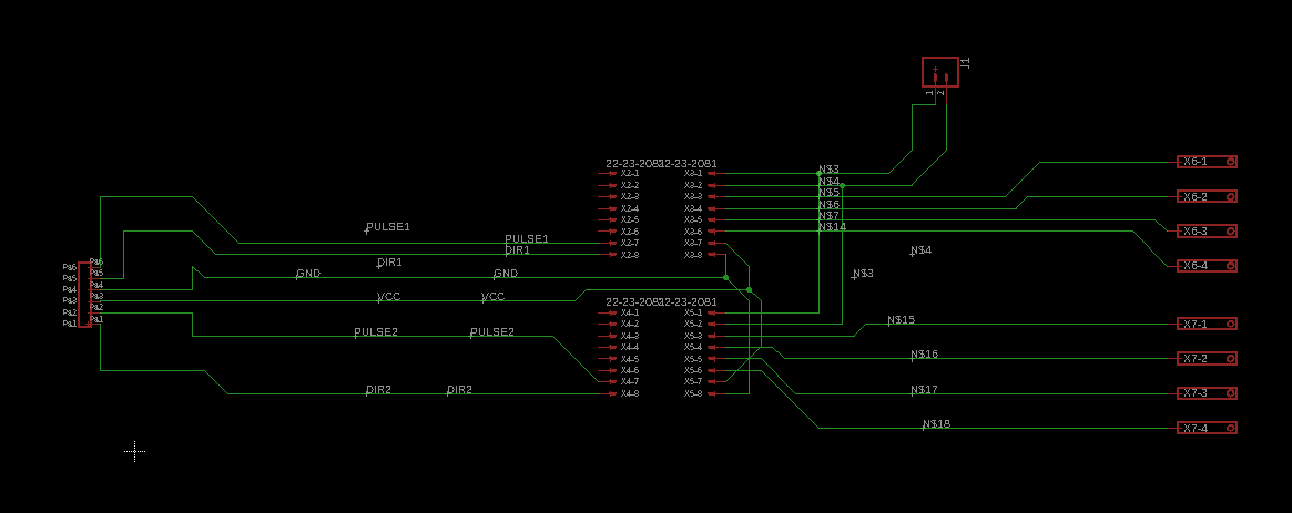
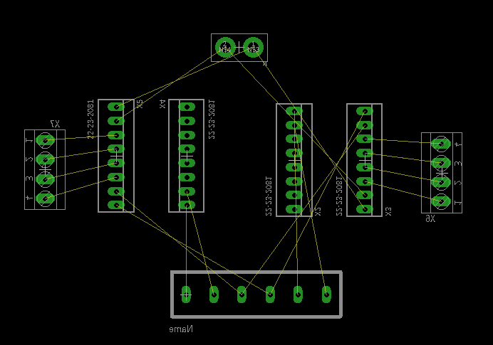
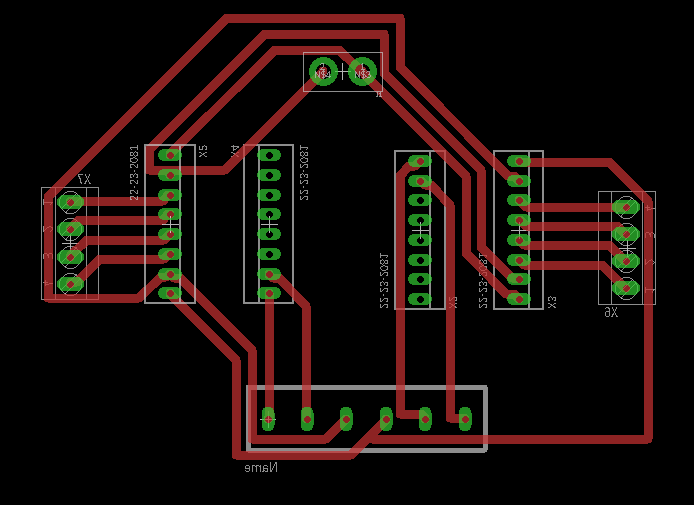
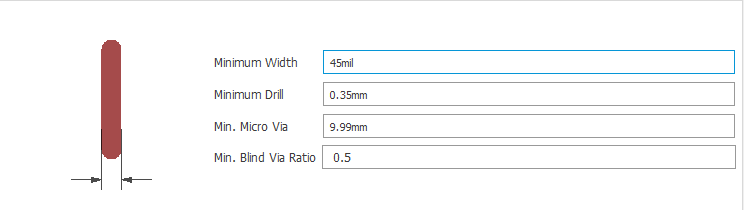
Before autorouting, I made sure my trace was thicker than normal since there will be high current passing trough them.
We will mill this board right now since durinjg our test we will have to drive our motor using this because a breadboard can't take such high current. so we do our usual process:
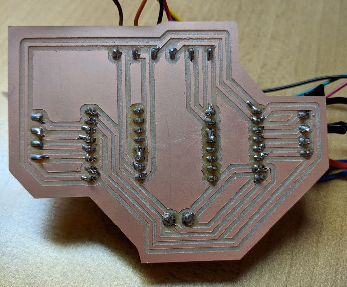
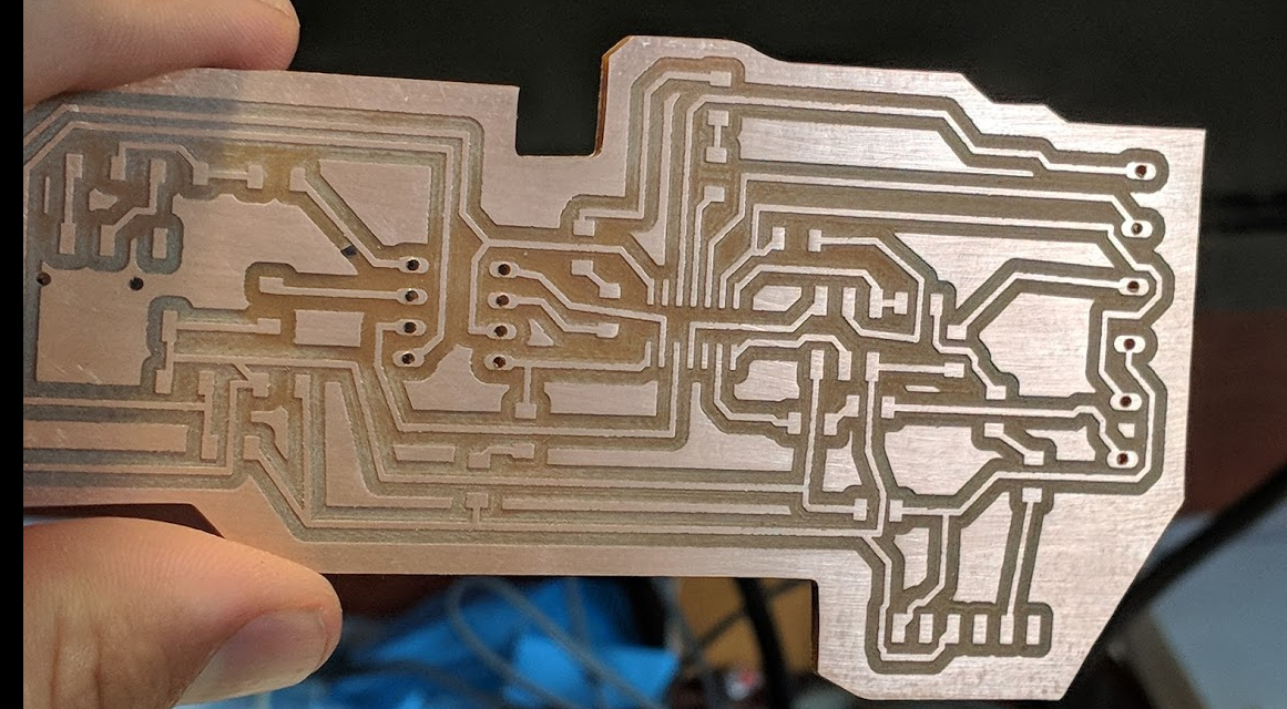
Here is the final board:
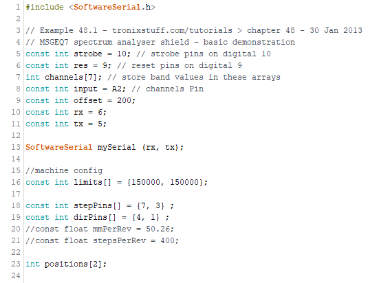
Ok, now that this board is done, we can write our code before testing the whole thing using our breadboard. The code I wrote is pretty simple but also very long, I will not explain everything, only the main part, here is the final code:
                                    #include <.SoftwareSerial.h>

// Example 48.1 - tronixstuff.com/tutorials > chapter 48 - 30 Jan 2013
// MSGEQ7 spectrum analyser shield - basic demonstration
const int strobe = 10; // strobe pins on digital 10
const int res = 9; // reset pins on digital 9
int channels[7]; // store band values in these arrays
const int input = A2; // channels Pin
const int offset = 200;
const int rx = 6;
const int tx = 5;

SoftwareSerial mySerial (rx, tx);

//machine config
const int limits[] = {150000, 150000};

const int stepPins[] = {7, 3} ;
const int dirPins[] = {4, 1} ;
//const float mmPerRev = 50.26;
//const float stepsPerRev = 400;

int positions[2];

void setup()
{
  mySerial.begin(9600);
  pinMode(res, OUTPUT); // reset
  pinMode(strobe, OUTPUT); // strobe
  digitalWrite(res, LOW); // reset low
  digitalWrite(strobe, HIGH);

  for (int motor = 0; motor < 2; motor++) {
    pinMode(stepPins[motor], OUTPUT);
    pinMode(dirPins[motor], OUTPUT);
    digitalWrite(stepPins[motor], LOW);
    digitalWrite(dirPins[motor], LOW);;

    //init positions in middle
    positions[motor] = limits[motor]/2;
  }
}

void loop()
{
  readMSGEQ7();
  int steps = map(channels[0], 0, 1024 - offset, 10, 300);
  moveMotor(steps, 0);
  delay(100);
  moveMotor(-steps, 1);

  //  For debugging
  for (int band = 0; band < 7; band++)
  {
    mySerial.print(channels[band], DEC);
    mySerial.print(" ");
    delayMicroseconds(500);
  }
  mySerial.println();
}

// Function to read 7 band equalizers
void readMSGEQ7()
{
  digitalWrite(res, HIGH);
  delayMicroseconds(200);
  digitalWrite(res, LOW);
  delayMicroseconds(200);

  for (int band = 0; band < 7; band++)
  {
    digitalWrite(strobe, LOW);
    delayMicroseconds(50);
    analogRead(input); //dummy read to allow value to settle

    int constrained = analogRead(input) - offset;
    if (constrained < 0){constrained = 0;}

    // store channels band reading
    channels[band] = constrained;
    delayMicroseconds(50);
    digitalWrite(strobe, HIGH); // strobe pin on the shield - kicks the IC up to the next band
    delayMicroseconds(50);
  }
}

//Steps indexed motor by given distance in step numbers
void moveMotor(int distance, int motor) {

  if (positions[motor] + distance > limits[motor]) {
    distance = limits[motor] - positions[motor];
  } else if (positions[motor] + distance < 0) {
    distance = -positions[motor];
  }
  positions[motor] += distance;

  if (distance < 0) {
    digitalWrite(dirPins[motor], LOW);
    distance =-distance;
  } else {
    digitalWrite(dirPins[motor], HIGH);
  }


  for (int i = 0; i < distance; i++) {
    digitalWrite(stepPins[motor], HIGH);
    delay(2);
    digitalWrite(stepPins[motor], LOW);
    delay(20);
  }
}
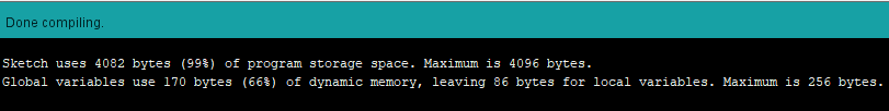
Before going into the code, one thing got me really mad and complicated things for me is that the attiny44 as a program storage space of only 4096 bytes, knowing that each character takes 8 bytes, this REALLY limit the complexity of the code we can write. I spent a lot of time trying to find ways to limit my code and for a long time I actually use 99% of the program storage space, I finally realised that I did'nt really use any float into my code so I replace all float into INT and that gave me a LOT of space (around 20%). Still I should have use a bigger MCU. maybe something like the ATMEL 328, like the arduino uno.
Anyway, the code do a couple of things, like I said it would take so long explain it all line by line, but here are the main tasks of the program:
First of all the we import the Software serial library, we define our global variable such as our pins number for the attiny and our channels array for the storage of ou multiplexer. We also sets limits so our machine won't go too far.
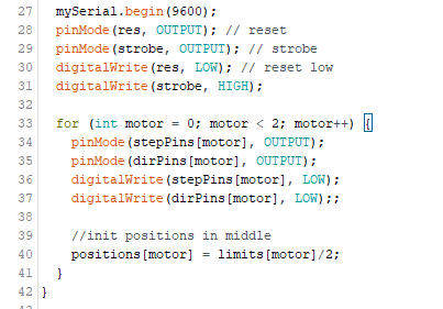
Once our variable are set, we can go on and write are setup, first thing is to start the software serial, and set our PINMODE and their status. we also initialize are 0 position as the middle of the machine and we write a for loop that store an array for our 2 steppers.
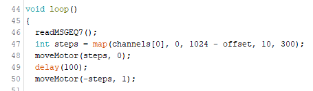
In our loop, we make our motor move one by one using our low frequency coming froms our MSGEQ7, The bigger the value on the bass, the longer the pen will go on its diagonal.
We also print our MSGEQ7 data into serial for debugging and visualation purposes.

Next we create the function to read our MSGEQ7 value, in this part, delays are important since the MSGEQ7 uses delay to strobe and reset:
I played around a bit with the delay and foud out with time that a 50 microsecond delay between each strobe was a good fit to get out good data from our chip.
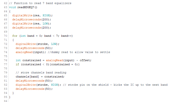
So in here we just let the MSGEQ7 do what it's gotta do, by switch the res pin and strobing every 50 microsecond in ou for loops that store into an array of 7 band.
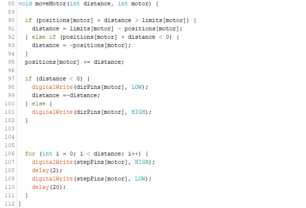
Next and finally we take care of the movement of our motor by indexing the step of our motor by given distance in step numbers. So in here we have a if condition that basicly ask the program to count the number of steps the motor has done and convert it into a "distance", if the motors goes too far, it will lock respecting our limits variable. if its ok, the motor will run.
Ok, so this is grosso modo our code, sure I did not do an in deph explanation of each line, but I think you get the idea. So now we could actually test the code! to do so, I replicate our MSGEQ7 board on a breadboard and try to read serial value that makes sense.
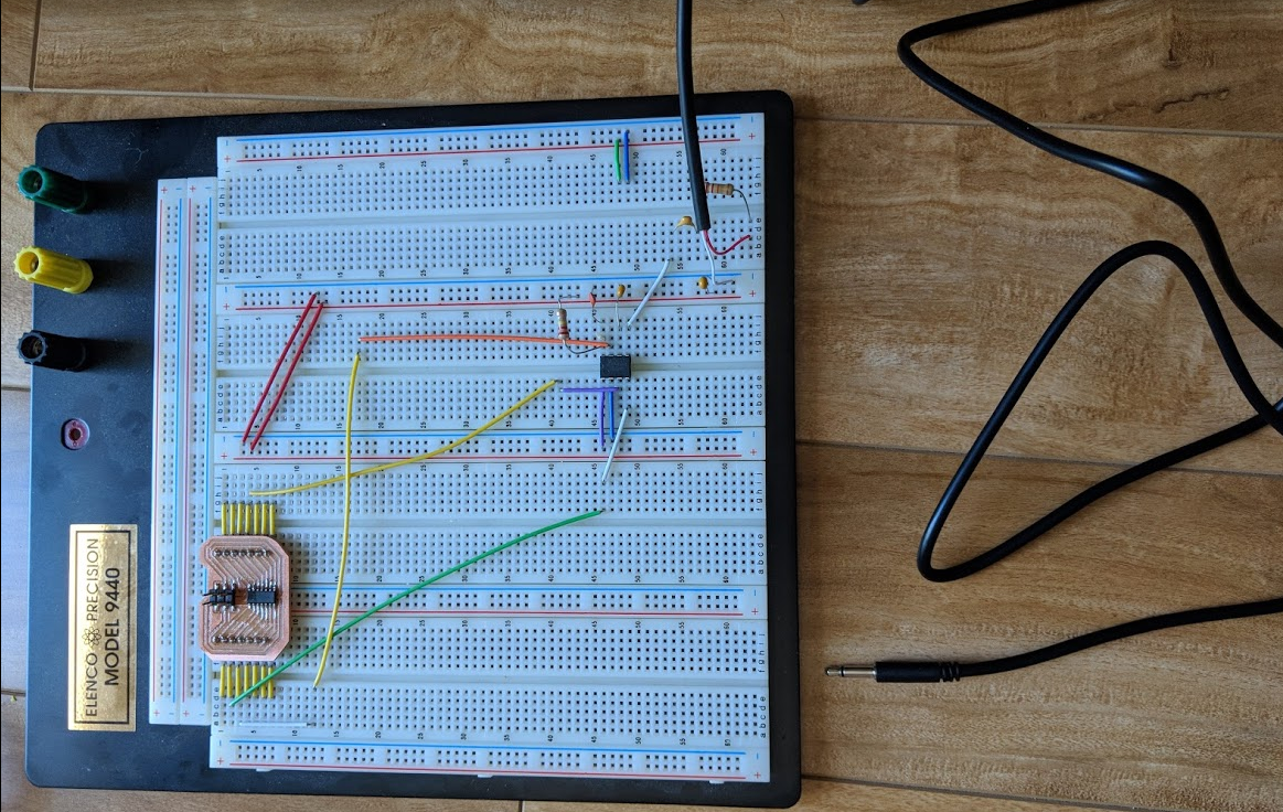
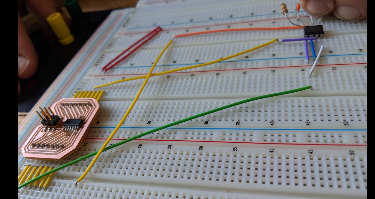
So without even connecting our motor driver board, I try to read serial data with my audio jack to see if the value we would get out would be making sense. and it did!
Alrright so now that we know that our circuit make sense, we can go on and mill our board!
Using the same process we went on and mill the final board
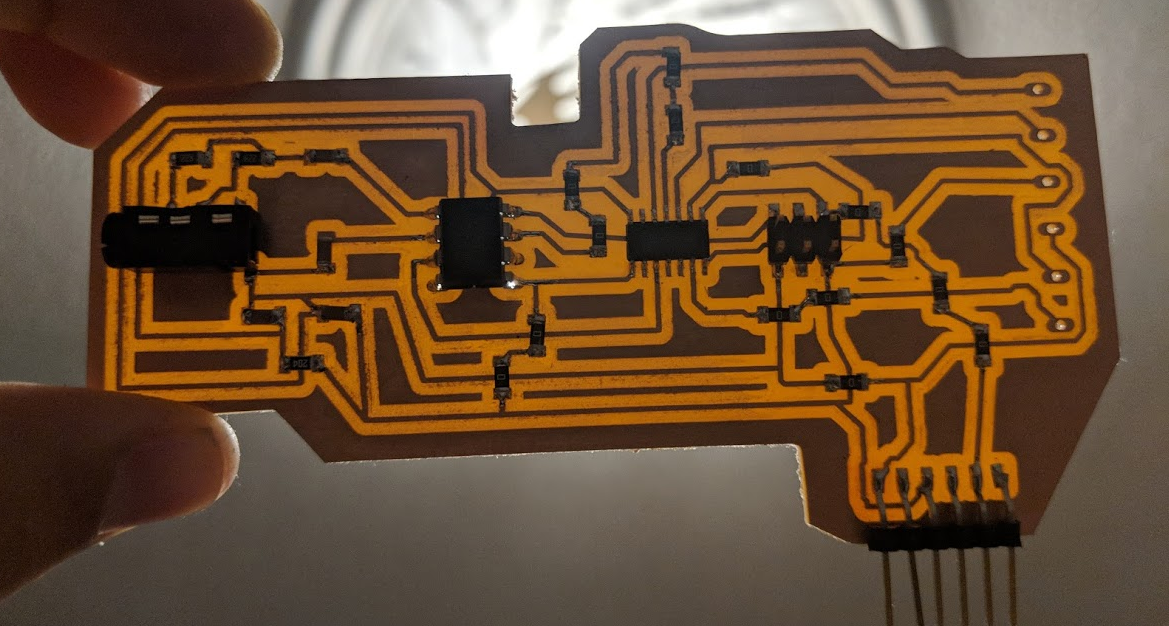
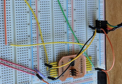
We can now connect everything to the machine and test again!
When I did the second test, I realised that while my jack audio was floating, I had a LOT of random noise when opening my 30V power supply, after some headache, I realise that my floating auxiliarry cable was just serving as an atenna, and when I opened my power supply, a lot of interference was capted. I then remembered that the DRV8825 was using a capacitor for decupling so I add it and it helps quite a bit. I now have clean 0 again while playing nothing!
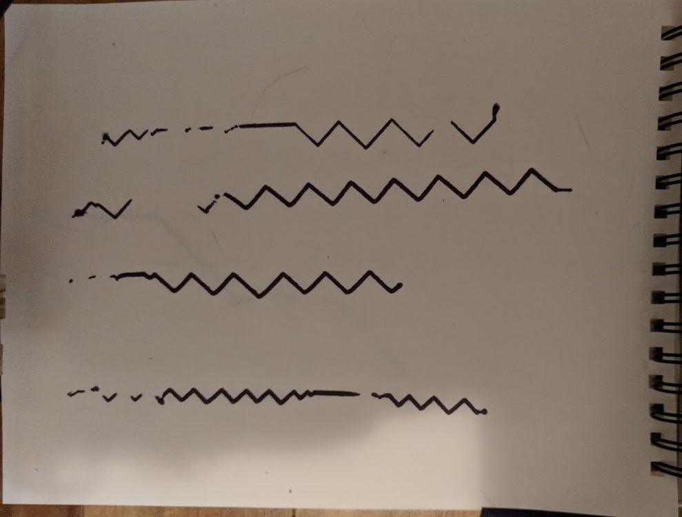
Once this was ok, I test the whole thing and here we go!!
Sure it is not perfect and I still have to make a better system integration of the electronics (I will do a case to fit everything inside) the result are not the best but it works! Next step is also to make a better pen holder and a lot of work can still be put in this project, but i'm really happy with it and it's a great first iteration in my mind! Thank you!
 Here
Here are my files!