WEEK5 : Electronic production
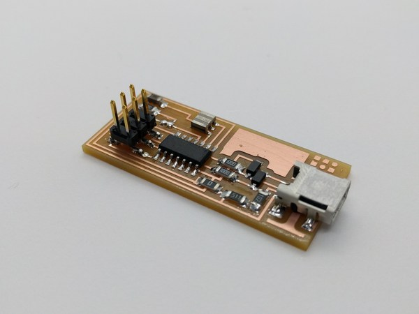
Fab ISP
Resources
Tutorials
- Electronics production, Tamiya 2017(The version I tried)
- Making FabtinyISP Brian(Latest, most recommended version)
Teaching Materials
Assignment
group:
- Characterize the specifications of your PCB production process.
individual:
- Make an in-circuit programmer by milling the PCB.
Group work
Asignment
Fabacademy official test pattern
We tried milling test pattern offered in fabacademy official page (link) and found out the capacity of our environment.
For the line thickness, 0.22mm was the minimum thickness that our milling machine (with best condition) can mill.
0.4mm was the minimum for the gap between lines. (as the diameter of the bit used was 1/64 inch = 0.396875mm)
See more info on group page.
Leveling sacrifice wood
Ensuring flat surface in the beginning is significantly important to get accuracy on milling. To do this, you first need to slightly shave the top of the wood.
Procedure is covered in group page, also on this article below.
Preparing data for milling
Get Fab ISP board design data from Archive Fabacademy 2018 week5
hello.ISP.44.res.cad
making rml data with mods
make “Trace”(circuit) rml data
go to mods
Programms > open server programm > SRM-20 > PCB
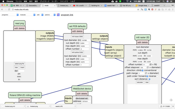
load png file to process
Read png > select png
add module to save
modules > file > save
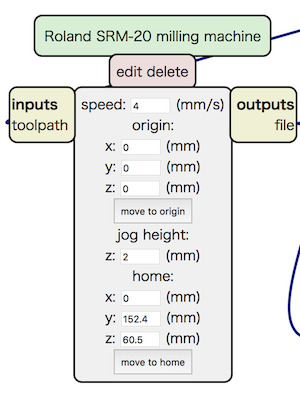
connect to “Roland SRM-20 milling machine”
->click output then click input in save file
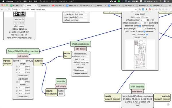
adjust parameters
Roland SRM-20 milling machine > origin
set x, y, z all to 0.
Calculate
mill raster 2D > calculate
rml file will be saved automaticaly
Check rml data
open exported rml and see last line.
If the line in the end of exported rml looked like this, it is an error try again.
PA;PA;!PZ0,NaN;PUNaN,NaN;!MC0;
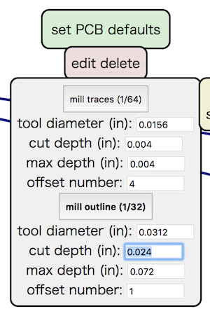
Make “Interior”(outline) rml data
Change following setting.
set PCB defaults >
- mill outline(1/64) to mill outline(1/32)
- cut depth parameter (if needed)
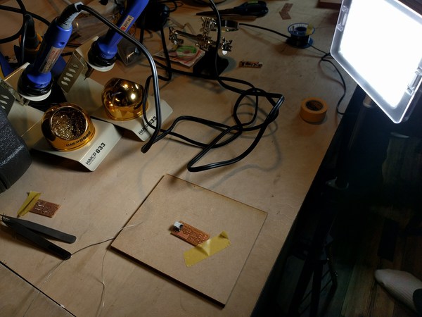
Hands-on milling with SRM-20
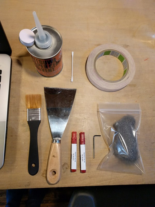
materials
- SRM-20 : Roland
- chemical wood (sacrifice wood)
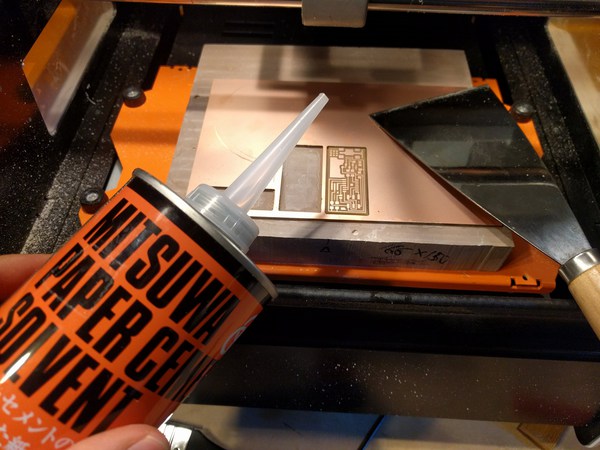
- solbent : MITSUWA PAPER CEMENT SOLVENT
- scraber (金属ヘラ)
- brash
- paper cutter
- steal wool
- ultrasonic cutter : 超音波小型カッター ZO-41(本多電子株式会社)
- two sided tape : Nitto No.5000NS
- board (FR1) : Sunhayato No.12 (カット基板 片面紙フェノール 100×150×1.6mm【NO12】)
- end mill bits (1/64 inch) : Carbi-Universal S/C MICROGRAIN 1/64 SE 2FL
- end mill bits (1/32 inch) : 1/32 SE 2FL
Milling with SRM-20
I. Process “trace”
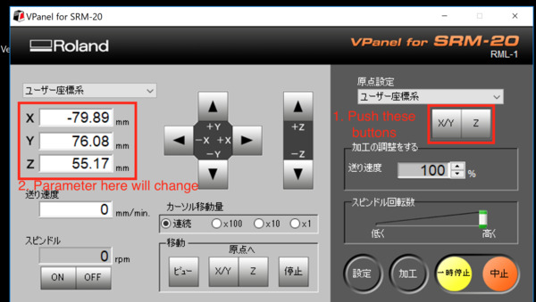
Open Vpanel for SRM-20
Set origin(原点合わせ)
- Move bit to the point you want to start milling.
Use the console in Vpanel. Be precise for x and y (horizontal) direction, for z stop few millimeters above the origin point.
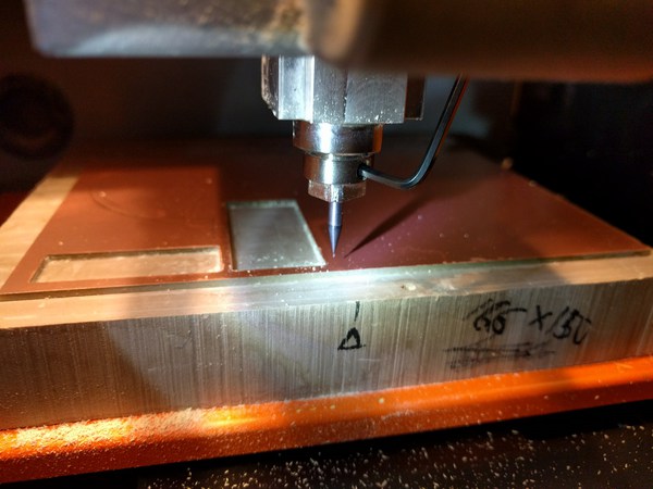
- Then drop the bit manually.
- set origin
In Vpanel interface(原点指定), push x/y and z button to set origin.
Start processing
- press process(加工)button and lunch window.
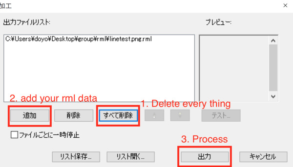
- Remove every thing in the list.
- Then add file you want to process (“trace” file).
- press output(出力)
II. Process"interior"
- Change bit to 1/32 inch
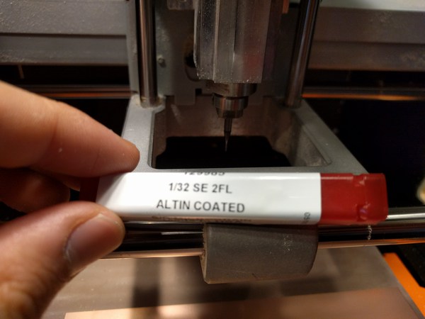
- Re-adjust z origin point
Always adjust z origin when you change bits.
* Be careful not to move xy origin. - process
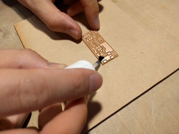
III. Finish
- Remove dust with brush
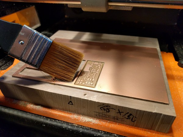
- Pour solvent in to the milled pit, use scraber to peal it off.
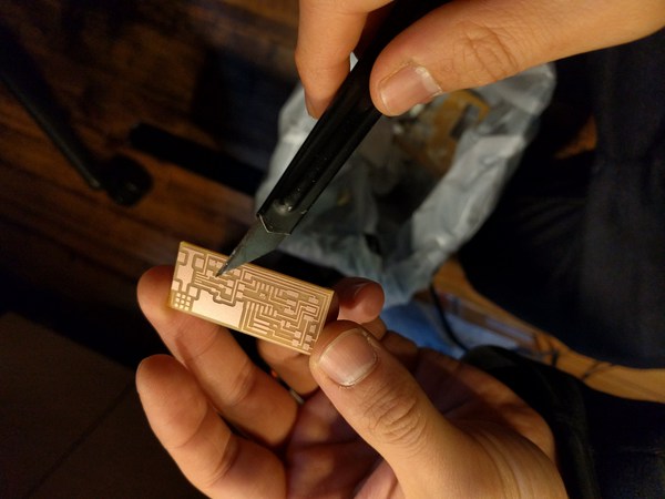
- Fillet corners with paper cutter
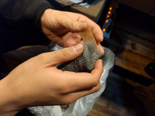
- Remove a flash with steal wool
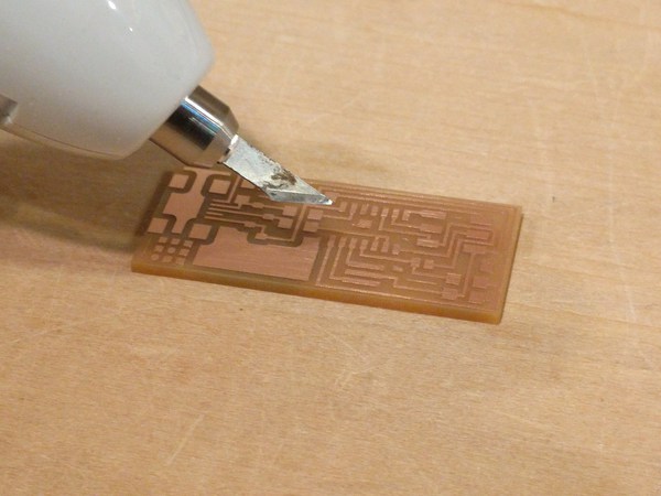
- Shave unnecessary part using ultrasonic cutter
Soldering
Material
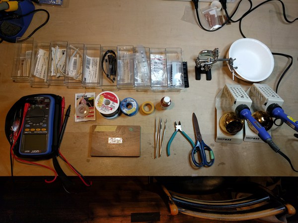
- flux : HOZAN H-722
- tweezers
- soldering iron : HAKKO FX600
- tip (small) : T18-C1 (1mm diameter, tip end cut diagonally)
- tip (large) : T18-B2(2mm diameter, tip end round type)
- solder (0.8mm) : スパークル70(千住金属工業株式会社)
- solder (0.3mm) : ソルペット SE-06003RMA
- desoldering wick : goot wick CP-1515(はんだ吸取線)
- masking tape
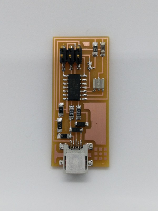
Parts
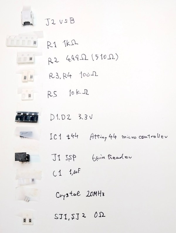
R1: Resistance 1k ohm (1000) x 1
R2: Resistance 499 ohm (4990) x 1
R3,R4: Resistance 100 ohm (101) x 2
R5: Resistance 10k ohm (1002) x 1
C1: Capacitor 1uF x 1
D1,D2: Zener diode 3.3V x 2
IC1: Attiny 44 x 1
20MHz: Resonator 20MHz x 1
SJ1,SJ2: Wire x 2
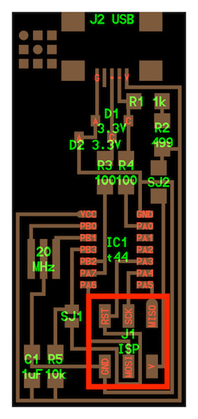
J1 ISP: Pin header 2x3 x 1
J2 USB: USB jack
Soldering iron use
T18-B2 (2mm) : USB jack and 2x3pin header
T18-C1 (1mm) : other parts
Process
-
Coat with flux
First of all, coat your board with flux right away before its surface get oxidized. Let it dry for a hour.
-
Start placing and soldering from USB socket
It will be difficult to place after you have other parts on the board as they block the soldering iron. -
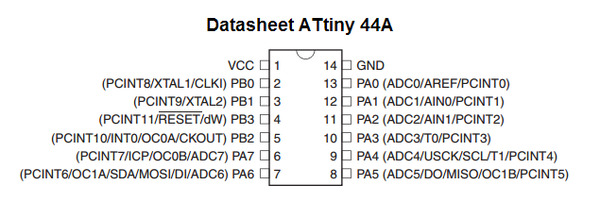
Solder SPU
*Careful with the direction! Small dot indicates pin1 (which is VCC pin in Attiny44A refer to the datasheet)
-
Solder resisters, capacitors and diodes
-
Place crystal
-
Place 2x3pin header
Basic rules for soldering
- Solder short parts first tall parts later.
USB(exception) > CPU > register > capacitor > diodes > crystal - First put thin layer of solder on a land, then place a part on a land and temporary tack it with soldering iron.
- After tacking parts at the right place, solder diagonal pin first and then move on to other pins.
- Check the connection.
Programming
Resources
- Fab ISP Programming Tutorial
- Electronics production, Tamiya 2017(write programmer with arduino)
You will need
- Your laptop
- FabISP (with jumpers soldered)
- AVR Programmer
- USB cables
Steps
Follow the instruction in the tutorial above.
- Get all softwares downloaded on the laptop
- Install CrossPack AVR
- Get XCode and command line tools
- Download firmware
- Wire up
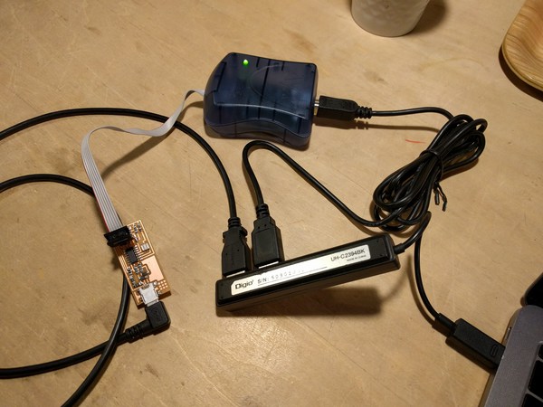
Wire up Fab ISP and programmer with PC.
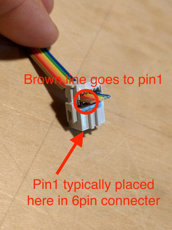
* Be careful for the direction of 6 pin connector. The red wire should go to V pin.
*(ATAVRISP2) Programmer Light Indicator Messages
- Green Light: means that the header is soldered correctly, the board is getting power.
- Yellow Light: means that the board is getting power, but most likely the 6-pin programming header is not soldered correctly (re-flow your solder joints / check for cold joints, check for shorts).
- Red Light: means that the board is not getting power - check for shorts.
-
In terminal, go to unziped firmware directory.
for example:
$ cd ~/Desktop/fabISP_mac.0.8.2_firmware -
Make changes on makefile (you can find it in firmware you downloaded) depends on which programmer you are going to use: other programmer, other FabISP programmer or Arduino.
The line in makefile you need to edit.
#AVRDUDE = avrdude -c usbtiny -p $(DEVICE) # edit this line for your programmer
AVRDUDE = avrdude -c avrisp2 -P usb -p $(DEVICE) # edit this line for your programmer
if you are using arduino:
AVRDUDE = avrdude -c stk500v1 -b19200 -P /dev/cu.usbmodem1421 -p $(DEVICE)
-
Compile firmware
$ make clean
If successful, you will get following response…
naitoukainoMacBook-Pro:kai-naito kai$ cd ~/desktop/firmware
$ make clean
rm -f main.hex main.lst main.obj main.cof main.list main.map main.eep.hex
main.elf *.o usbdrv/*.o main.s usbdrv/oddebug.s usbdrv/usbdrv.s
Then,
$ make hex
You will get this if the process succeeded.
naitoukainoMacBook-Pro:firmware kai$ make hex
avr-gcc -Wall -Os -DF_CPU=20000000	 -Iusbdrv -I. -DDEBUG_LEVEL=0
-mmcu=attiny44 -c usbdrv/usbdrv.c -o usbdrv/usbdrv.o
avr-gcc -Wall -Os -DF_CPU=20000000	 -Iusbdrv -I. -DDEBUG_LEVEL=0
-mmcu=attiny44 -x assembler-with-cpp -c usbdrv/usbdrvasm.S -o usbdrv/usbdrvasm.o
avr-gcc -Wall -Os -DF_CPU=20000000	 -Iusbdrv -I. -DDEBUG_LEVEL=0
-mmcu=attiny44 -c usbdrv/oddebug.c -o usbdrv/oddebug.o
avr-gcc -Wall -Os -DF_CPU=20000000	 -Iusbdrv -I. -DDEBUG_LEVEL=0
-mmcu=attiny44 -c main.c -o main.o
avr-gcc -Wall -Os -DF_CPU=20000000	 -Iusbdrv -I. -DDEBUG_LEVEL=0
-mmcu=attiny44 -o main.elf usbdrv/usbdrv.o usbdrv/usbdrvasm.o usbdrv/oddebug.o
main.o
rm -f main.hex main.eep.hex
avr-objcopy -j .text -j .data -O ihex main.elf main.hex
avr-size main.hex
   text	   data	    bss	    dec	    hex	filename
      0	   2020	      0	   2020	    7e4	main.hex
- Set ISP to use the external clock (crystal)
Type
$ make fuse
on terminal, then you will get
You should get this feedback from the system

naitoukainoMacBook-Pro:firmware kai$ sudo make fuse
avrdude -c usbtiny -p attiny44  -U hfuse:w:0xDF:m -U lfuse:w:0xFF:m

avrdude: AVR device initialized and ready to accept instructions

Reading | ################################################## | 100% 0.01s

avrdude: Device signature = 0x1e9207
avrdude: reading input file "0xDF"
avrdude: writing hfuse (1 bytes):

Writing | ################################################## | 100% 0.00s

avrdude: 1 bytes of hfuse written
avrdude: verifying hfuse memory against 0xDF:
avrdude: load data hfuse data from input file 0xDF:
avrdude: input file 0xDF contains 1 bytes
avrdude: reading on-chip hfuse data:

Reading | ################################################## | 100% 0.00s

avrdude: verifying ...
avrdude: 1 bytes of hfuse verified
avrdude: reading input file "0xFF"
avrdude: writing lfuse (1 bytes):

Writing | ################################################## | 100% 0.01s

avrdude: 1 bytes of lfuse written
avrdude: verifying lfuse memory against 0xFF:
avrdude: load data lfuse data from input file 0xFF:
avrdude: input file 0xFF contains 1 bytes
avrdude: reading on-chip lfuse data:

Reading | ################################################## | 100% 0.00s

avrdude: verifying ...
avrdude: 1 bytes of lfuse verified

avrdude: safemode: Fuses OK

avrdude done.  Thank you.
if successful.
- Program the board to be an ISP programmer.
Type
$ make program
You should get following respond.
naitoukainoMacBook-Pro:firmware kai$ sudo make program
password:
avrdude -c usbtiny -p attiny44  -U flash:w:main.hex:i

avrdude: AVR device initialized and ready to accept instructions

Reading | ################################################## | 100% 0.01s

avrdude: Device signature = 0x1e9207
avrdude: NOTE: FLASH memory has been specified, an erase cycle will be performed
         To disable this feature, specify the -D option.
avrdude: erasing chip
avrdude: reading input file "main.hex"
avrdude: writing flash (2020 bytes):

Writing | ################################################## | 100% 5.68s


avrdude: 2020 bytes of flash written
avrdude: verifying flash memory against main.hex:
avrdude: load data flash data from input file main.hex:
avrdude: input file main.hex contains 2020 bytes
avrdude: reading on-chip flash data:

Reading | ################################################## | 100% 3.36s


avrdude: verifying ...
avrdude: 2020 bytes of flash verified

avrdude: safemode: Fuses OK

avrdude done.  Thank you.

avrdude -c usbtiny -p attiny44  -U hfuse:w:0xDF:m -U lfuse:w:0xFF:m

avrdude: AVR device initialized and ready to accept instructions

Reading | ################################################## | 100% 0.01s

avrdude: Device signature = 0x1e9207
avrdude: reading input file "0xDF"
avrdude: writing hfuse (1 bytes):

Writing | ################################################## | 100% 0.00s

avrdude: 1 bytes of hfuse written
avrdude: verifying hfuse memory against 0xDF:
avrdude: load data hfuse data from input file 0xDF:
avrdude: input file 0xDF contains 1 bytes
avrdude: reading on-chip hfuse data:

Reading | ################################################## | 100% 0.00s

avrdude: verifying ...
avrdude: 1 bytes of hfuse verified
avrdude: reading input file "0xFF"
avrdude: writing lfuse (1 bytes):

Writing | ################################################## | 100% 0.00s

avrdude: 1 bytes of lfuse written
avrdude: verifying lfuse memory against 0xFF:
avrdude: load data lfuse data from input file 0xFF:
avrdude: input file 0xFF contains 1 bytes
avrdude: reading on-chip lfuse data:

Reading | ################################################## | 100% 0.00s

avrdude: verifying ...
avrdude: 1 bytes of lfuse verified

avrdude: safemode: Fuses OK

avrdude done.  Thank you.
Done!
Enabling as a programmer
You need to remove jumper wires to enable the board as a programmer. Take away 0 ohm resister and the solder bridge indicated as “SJ” in the board diagram.
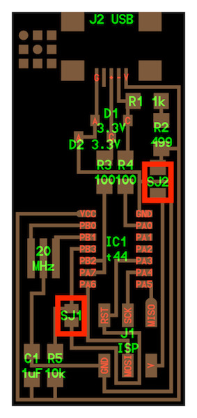

Now FabISP could be used as a programmer.
Check whether FabISP is recognized in MacOS.
Mac > About this Mac > System report

You can see FabISP under USB port if your FabISP is recognized.
Trouble shooting
-
The first time I tried
$ make hex, I got thisavr-gcc -Wall -Os -DF_CPU=20000000 -Iusbdrv -I. -DDEBUG_LEVEL=0 -mmcu=attiny44 -c usbdrv/usbdrv.c -o usbdrv/usbdrv.o
make: avr-gcc: No such file or directory
make: *** [usbdrv/usbdrv.o] Error 1
I succeeded to get rid of this by establishing path through.
Here is useful reference for making path…Qiita
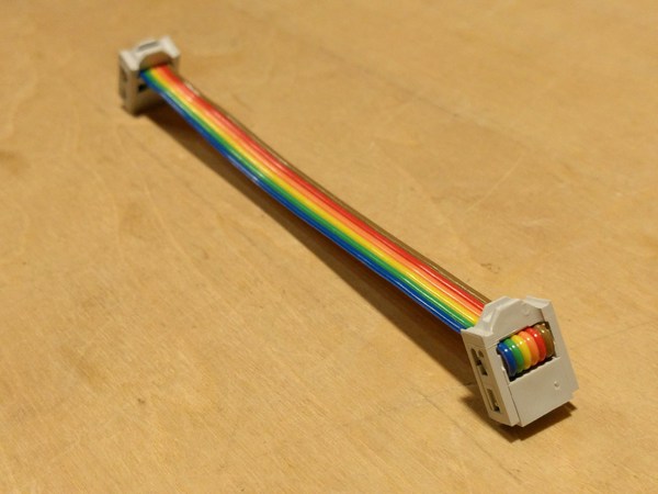
Making connector
Make 6pin head connector we will be using from next week. Will use it to wire Fab ISP(programmer) and IC to write program in.
Insert wires in the right position.
Squeeze it with a cramp to fix wire.
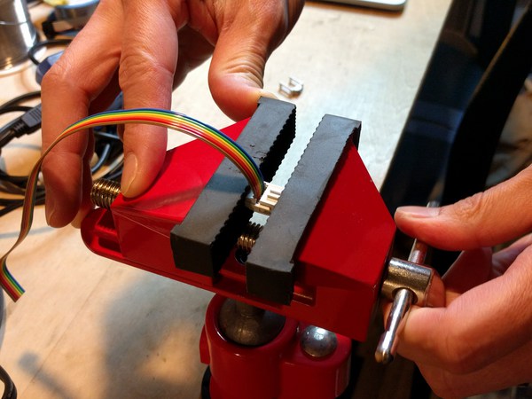
Put a cap on to bend wire 180deg.
Done.