14. Network and Communication
This week I worked with I2C to create a simple network between two custom pcb boards. I also did further work on my final project.
Final Project Work
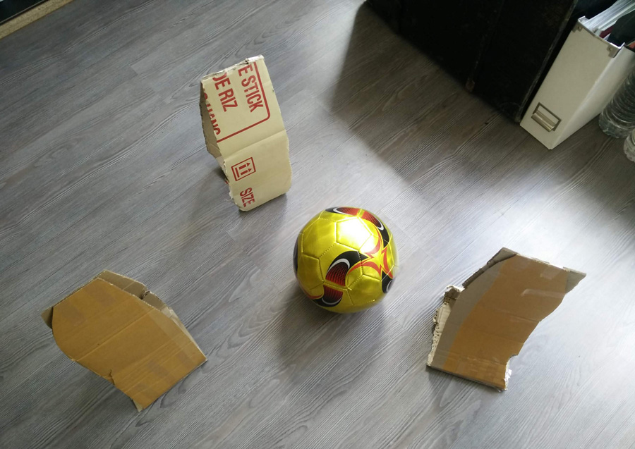
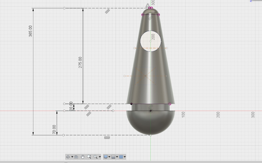
As a rough guide of the buoys, I cut the proposed dimensions (150 x 365mm) with cardboard and compared it to a football. In Fusion 360, I worked out the dimensions of the base and lighting section, including the position of the thread on the interior.
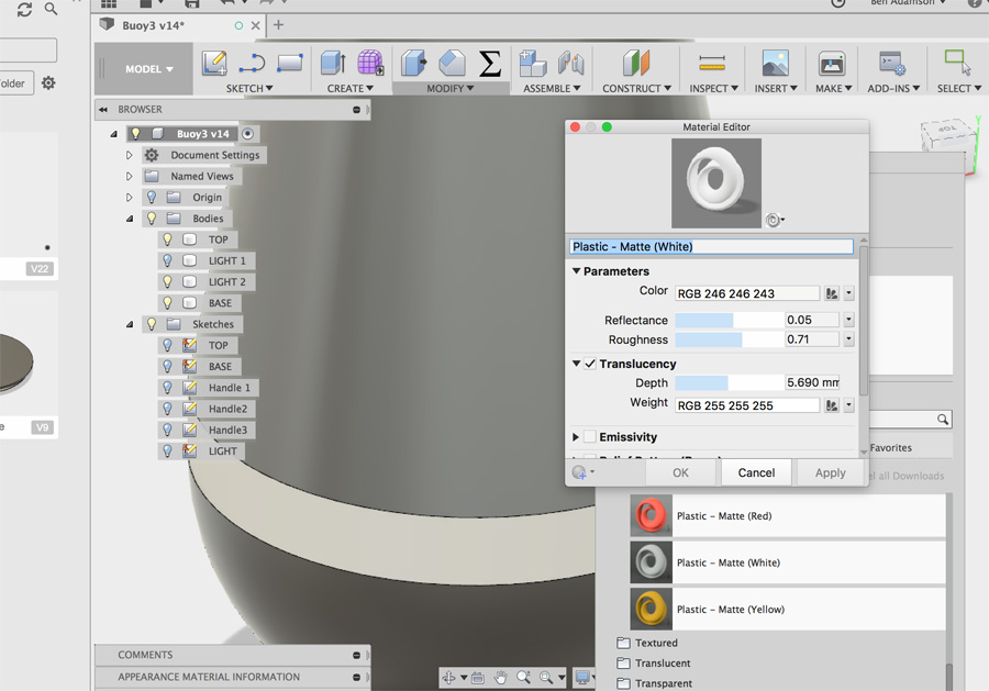
I spent time on a subsection which would be dedicated to a light (possibly a strip of LEDs). In the image above, I used the appearance settings and transparency to assign reference material.
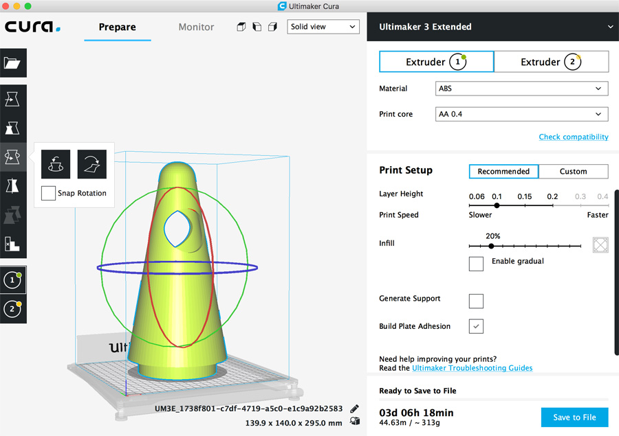
The issue going forward is print time – At the current dimensions, the top section (150 x 295mm) alone would take three days! I had to consider alternatives.
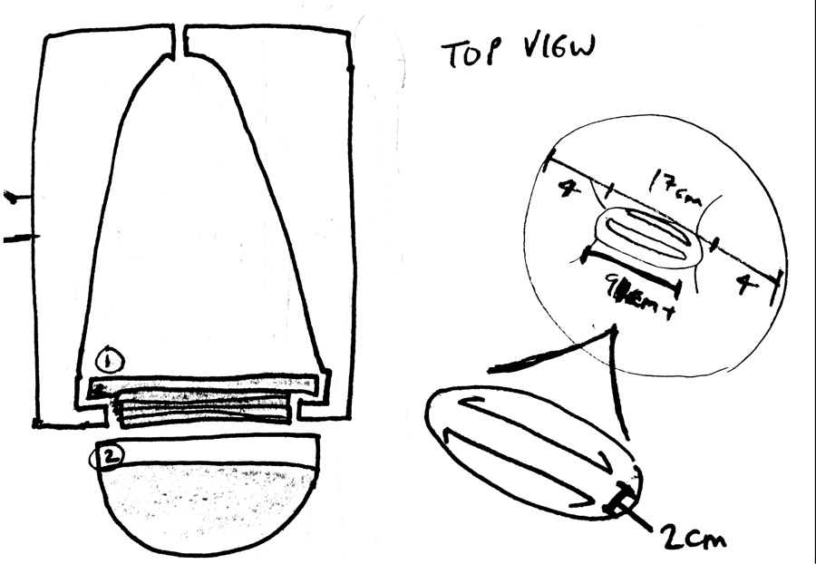
One possible option would be to combine the best of 3D printing (the creation of the thread top and base) and combine it with a rotational mold. This would require plugging the upper thread into a 3D mold so that it would combine with the liquid molding.
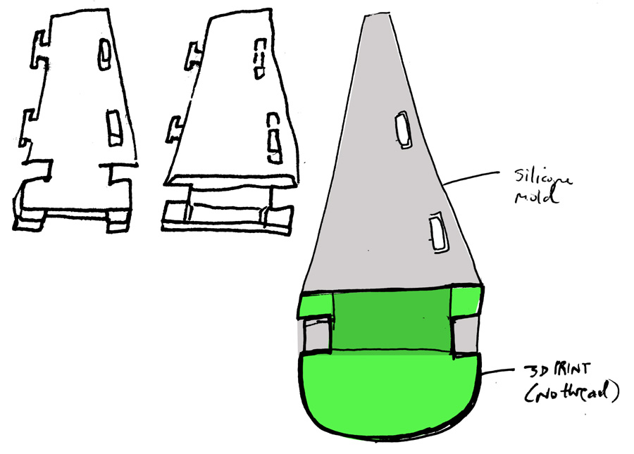
Another option would be to build the top of the buoy as a flat piece of silicone that could be folded into a cone shape. The image above shows how the base (3D printed) could be adapted to position and support the top. Because the top is flexible, it could be squeezed into a gaps in the base, thereby locking it into place.
I continue work on my final project in week 15 mechancial design.
Eagle
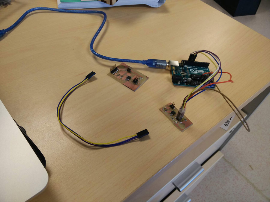
I read a tutorial to better understand I2C communication. Although I wish to use wireless communication in my final project, it seemed good practice to create a wired network first and gain an understanding for master/slaves and how they work together.
For the assigment we would use a type of communication known as Master/Slave. This is where one board is assigned the 'unidirectional' control over other boards, allowing it to control them.
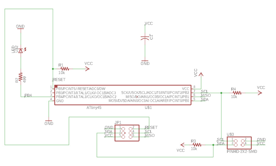
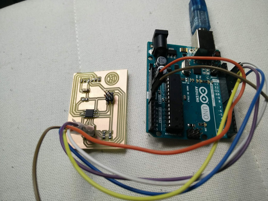
For the master (bridge) board I based them closely on the samples given by Neil. It proved challenging to match the schematic, but the more I understood about I2C the easier I could do this. I included a FTDI header, to allow serial communication from the computer to the master.
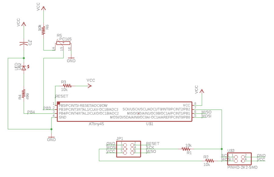
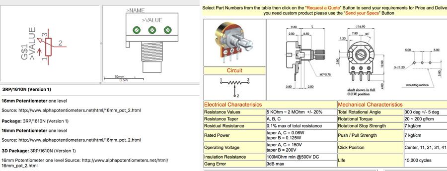
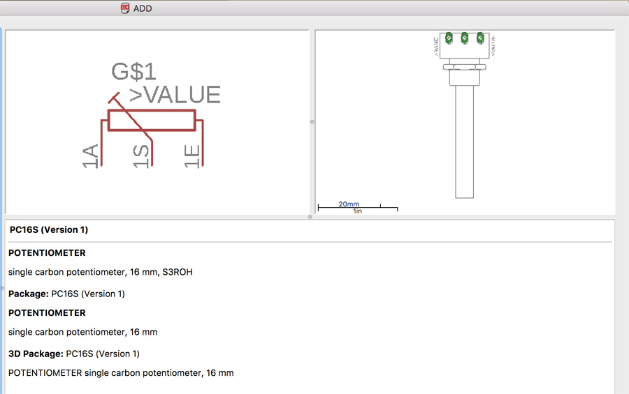
For variation I attempted to include a potentiometer on the master. I found a matching component on a potentiometer website. I later abandoned this idea because I felt there was not enough pins on the ATTiny 45. For the slave, I included an LED.
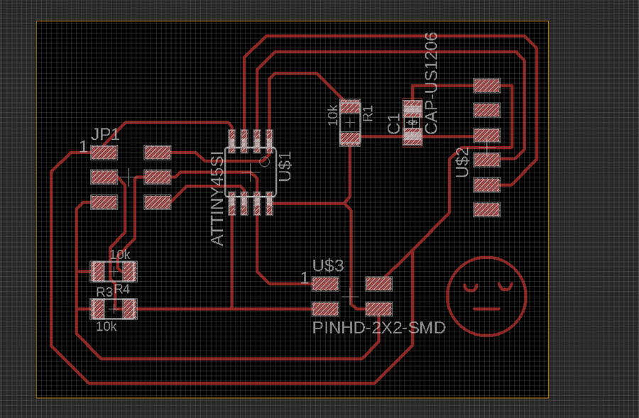
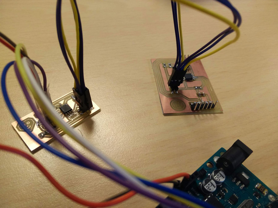
Routing the direction of traces proved challenging and it was necessary to run through the gap between different components to link all correctly. There was a little bit of back and forth to Fabmodules when certain routing merged, but I improved my ability with Eagle over time. Using the move + alt key really helped in this instance – Moving at smaller increments but still keeping the routing straight. I added a wee character to each board: Just for fun!
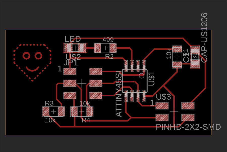
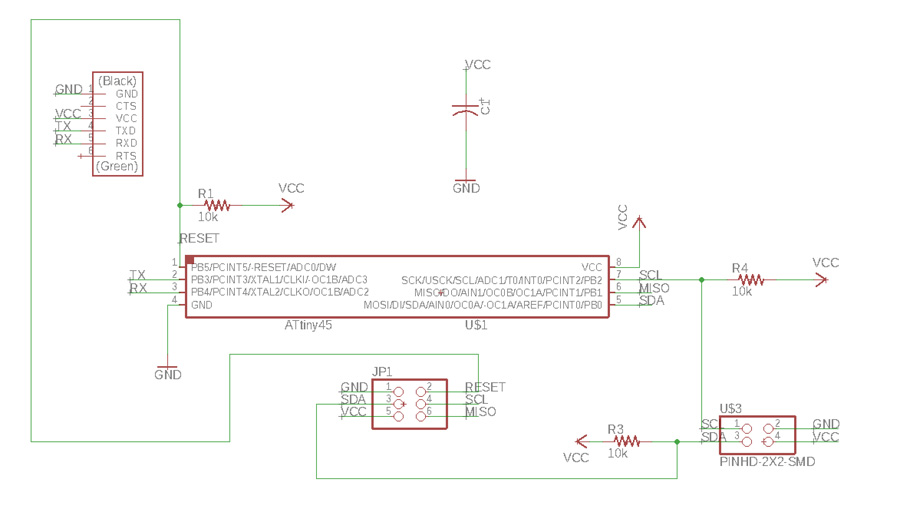
For the slave (node) board, things went smoother – I layed out the schematic including an LED so that instructions could be sent from the master and indicate feedback. I routed the node in a similar way to master, going beneath the ATTiny and through six and four-pin headers as required.
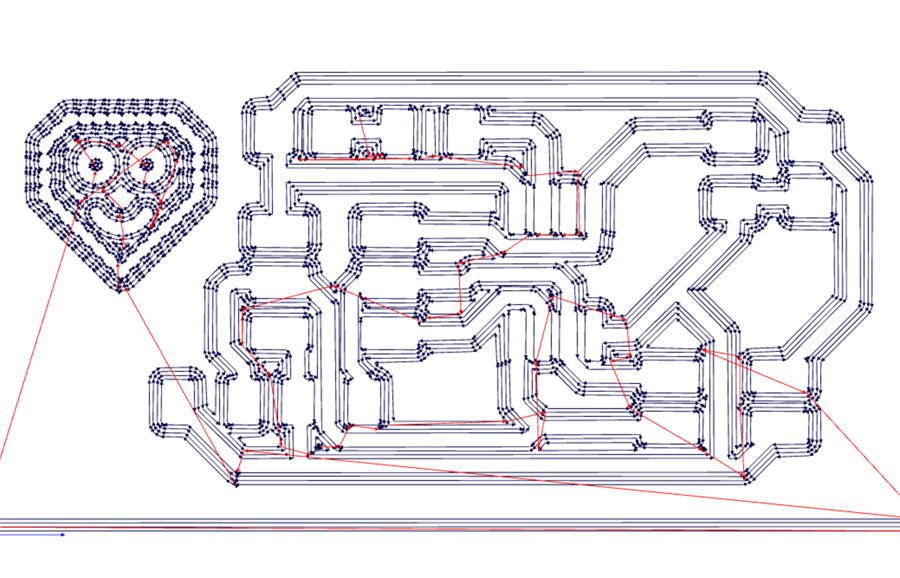
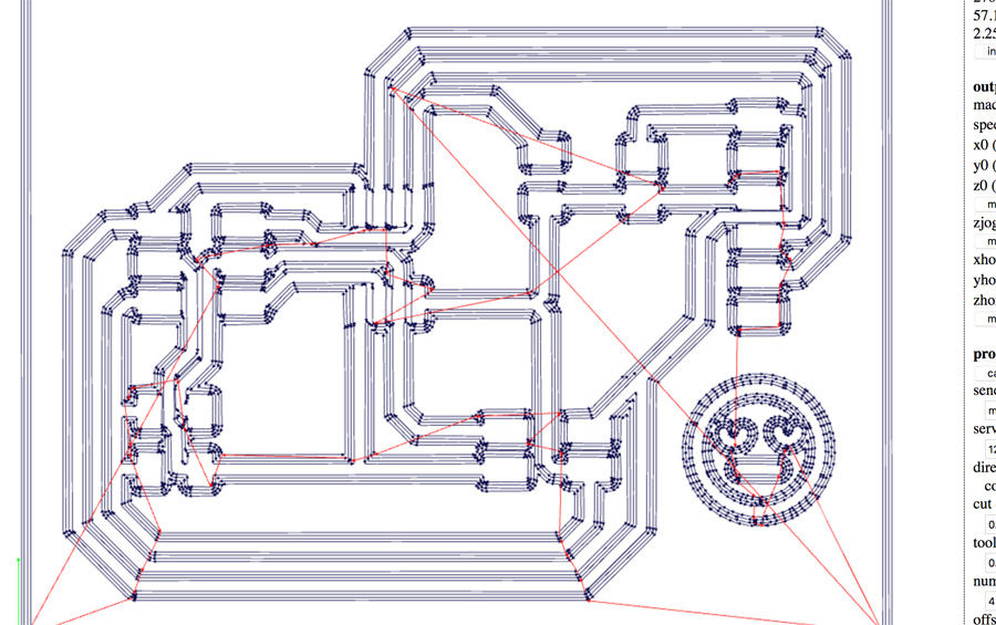
After inverting the board dimensions to white in Photoshop, I ran the pngs through Fab Modules to create two RML files.
SRM-20 & Components

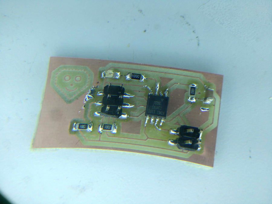
I soldered the following surface mounted (SMD) components for the two boards,
Master
- Right-angle 6-pin header (for FTDI serial communication)
- 2x3 pin header (to program board from Arduino)
- 2x2 pin header (to relay network signal from master to slave)
- 1Uf capacitor x1
- 10k resistor x3
- ATTiny 45 x1
Slave
- 2x3 pin header
- 2x2 pin header
- 1Uf capacitor x1
- 499 resistor x1
- 10k resistor x3
- ATTiny 45 x1
- 1206 red LED x1
Programming
I reviewed the notes from former student Aser Nabil. I also reviewed the notes from Neil's lecture and tried to combine the programs into something that would work with my boards.
I converted the Arduino board into a programmer, burned the bootloader and uploaded a program (MasterI2C-Basic2-Master.ino) on to the master board.
#include **TinyWireM.h**
int selection=1;

void setup(){
    TinyWireM.begin();
}

void loop(){
  TinyWireM.beginTransmission(0x05);
  TinyWireM.send(1);
  TinyWireM.endTransmission();
  delay(500);
}
The script declares an integer to send over the network and uses the TinyWire library to associate the address at 0x05 to the Transmission. A delay of 500 miliseconds is added to space the looped message. The script uploaded but it was difficult to know if it worked because there was no output component, eg. LED.
I checked the equivalent analog Arduino pins for SCL and SDA using a schematic. I then uploaded the following script for the slave board (I2C-Basic1-Slave.ino)
void setup() {

  TinyWireS.begin(I2C_SLAVE_ADDR);

  pinMode(4, OUTPUT);
  digitalWrite(4, LOW);
}

void loop() {
  byte byteRcvd = 0;
  if (TinyWireS.available()){

    byteRcvd = TinyWireS.receive();
      if (byteRcvd == 0x01){
          digitalWrite(4, HIGH);
          delay(2000);
          digitalWrite(4, LOW);
          delay(2000);
          digitalWrite(4,HIGH);
      }
  }
}
The file uploaded but when I connected the master to the slave with the four pin header (and the FTDI to the six-pin) there was no activity on the serial monitor.
It was time to simply things, by testing a basic program to light the led on the slave only. The slave's LED lit up on successive blinks (basic-led.ino).
void setup() {
  // put your setup code here, to run once:

 pinMode(4, OUTPUT);


}

void loop() {
  // put your main code here, to run repeatedly:
   digitalWrite(4, HIGH);
  delay(1000);
  digitalWrite(4, LOW);
  delay(1000);
}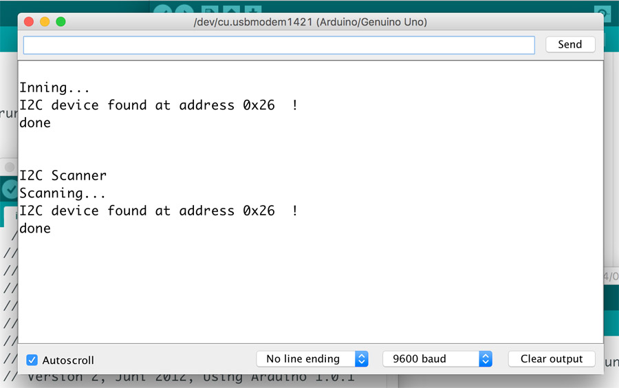
It was clear that we needed to test the slaves ability to operate with I2C. I used the I2C Scanner program to test communication between the Arduino (as a master) and the slave. I used the following Tools settings,
- Board: Genuino/Arduino Uno
- Programmer: AVRISP mkll
Then instead of connecting the four pins as with the master board, I connected the slave with two pins (SCL and SDA) with the Arduino. I checked the pin outs on an Arduino diagram. I uploaded the scanner program and opened the serial monitor. The slave was detected (as per the image) at address 0x05.
I then connected the slave to Arduino Master via same four pin. I used the following script (arduinomaster-test.ino),
#include **Wire.h**
void setup() {
  Wire.begin();
  Serial.begin(9600);
  Serial.println("test");
}

void loop() {
    Wire.beginTransmission(0x05);
    Wire.write(0x01);
    Wire.endTransmission();
    delay(3000);
I set the Arduino as a programmer using the Example > Arduino as ISP. I failed to get the pickup the communication to light the LED.
I then connected the master only (with six pin) and uploaded the following program (MasterI2C-Basic2-Master.ino),
        int selection=1;

void setup(){
    TinyWireM.begin();

}
void loop(){


  TinyWireM.beginTransmission(0x05);
  TinyWireM.send(1);
  TinyWireM.endTransmission();
  delay(500);
}
The program uses the TinyWireS library to connect to the slave over I2C. Output pins are defined to match the ATTiny pins. An if statement declares that if the TinyWireS message (1) is received, to print 0 in succession.
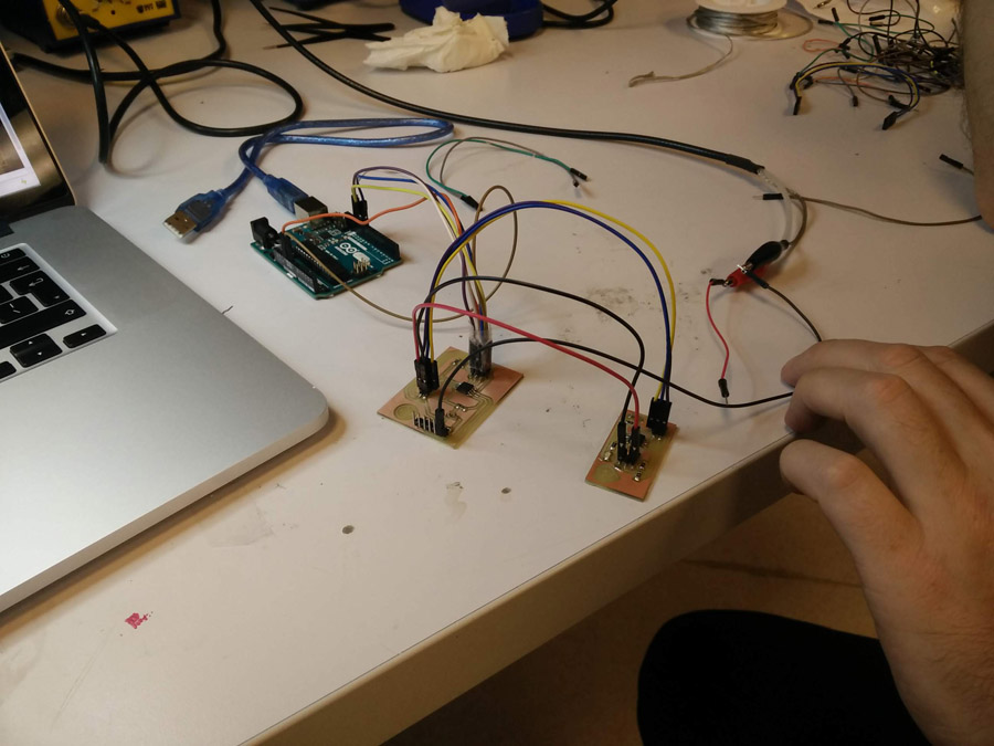
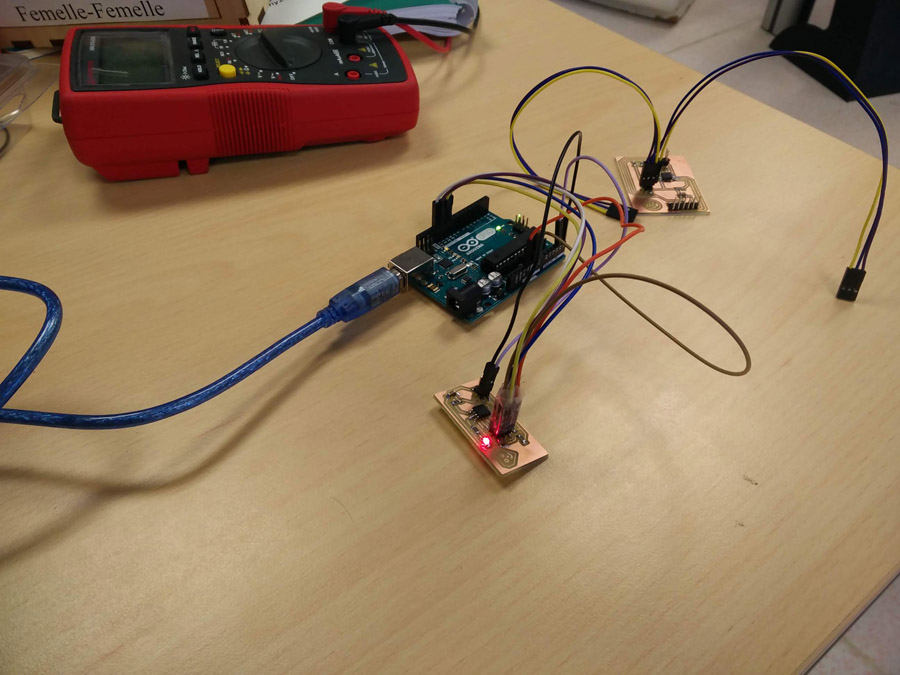
We then tested boards communication with the oscilloscope. The six pin leads we attached to the arduino in the same manner, while the four-pins on the master were connected to each other. GND on the master was then connected to the oscilloscope GND. This setup was varied to test the slave.
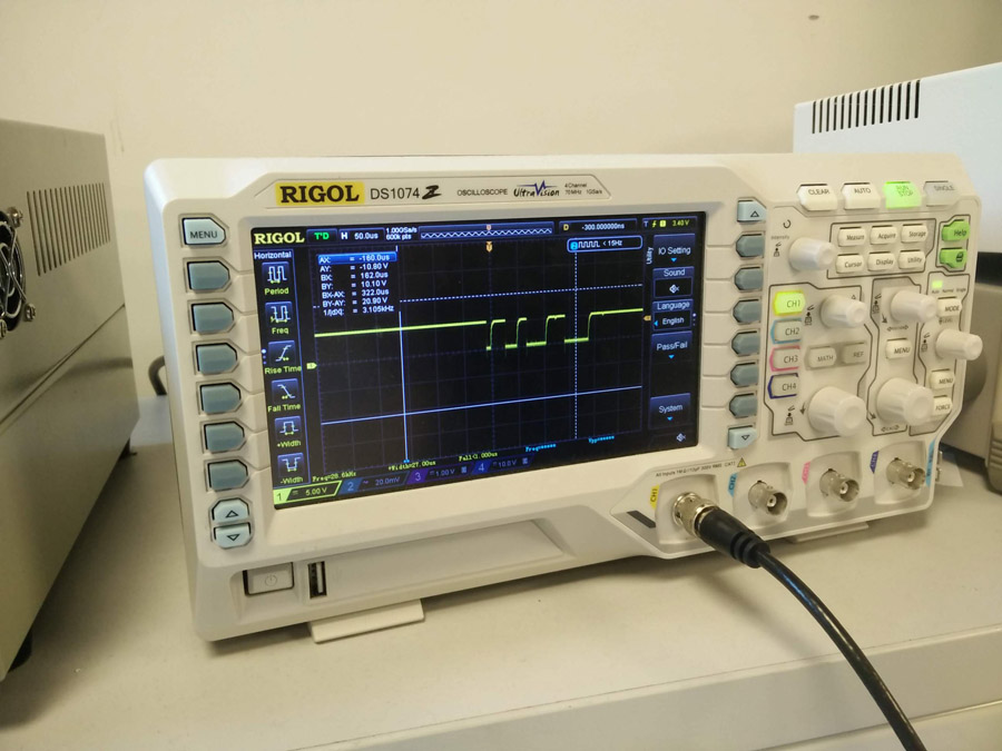
The oscilloscope indicated that the boards were communicating on the I2C bus comparative to the code – On regular intervals. SDA transmits 5V except when communicating (above, zoomed in).
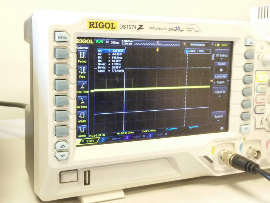
SCL transmits 0V except when communicating (above, zoomed out).
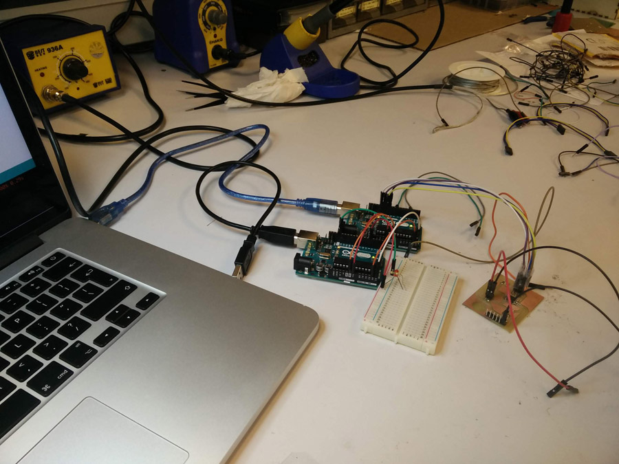
In a further step, we checked if a second arduino operating as a slave could interact with the master board. To this arduino we attached an led via breadboard. Despite a working signal, we did not get led to blink as expected.
04/06/2018: Got the master and slave boards working. In a final step, the following was changed to get the master to communicate with the slave,
- The Arduino was converted to a programmer (and subsequently the master and slave boards) at 8Mhz rather than 1Mhz
- The address was changed from 0x26 to 0x05 (updated on this page)
- An alternative female-female cable was used