6. 3D Scanning and Printing
This week we learnt to use a Shining 3D EinScan-Pro scanner and Ultimaker 3 printer. I also spent time in Fusion 360 on my final prototype.
3D Printing
In starting this assignment, I considered my the shape of my final prototype and how I would be assembled. I sketched more detail on its form - I knew I needed to support a counter weight and electronics in the base. I wanted to make this easily accessible so that, for example, the bottom of the base could be filled with sand. This would allow easy transport of the device at a later stage and keep down the cost of using heavy metallic material.
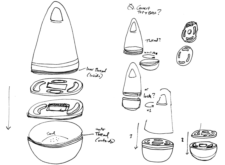
Above: Potential assembly of overall components and locking mechanisms
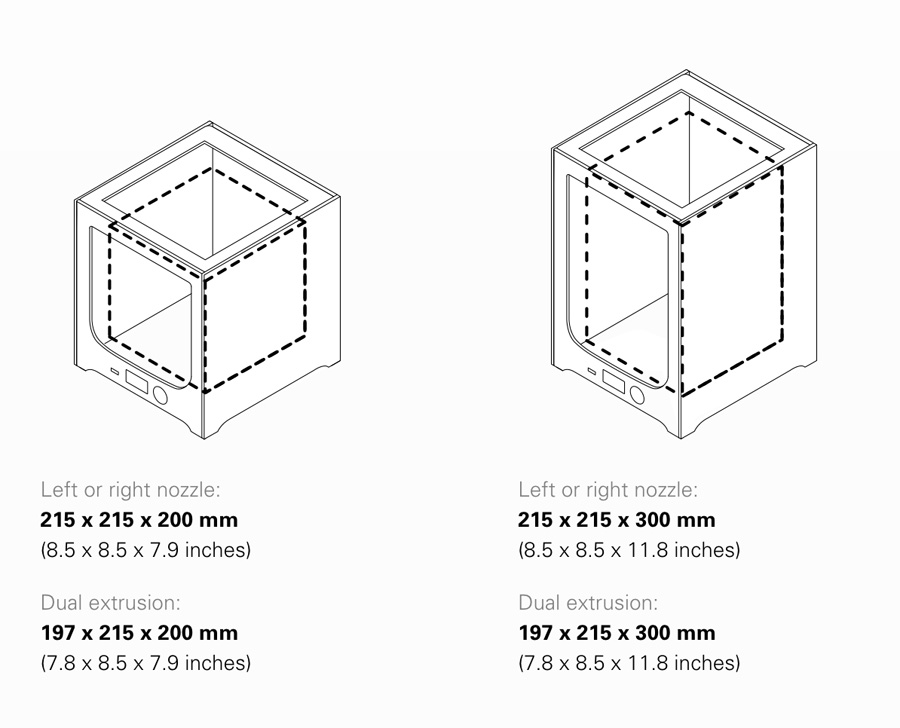 image source
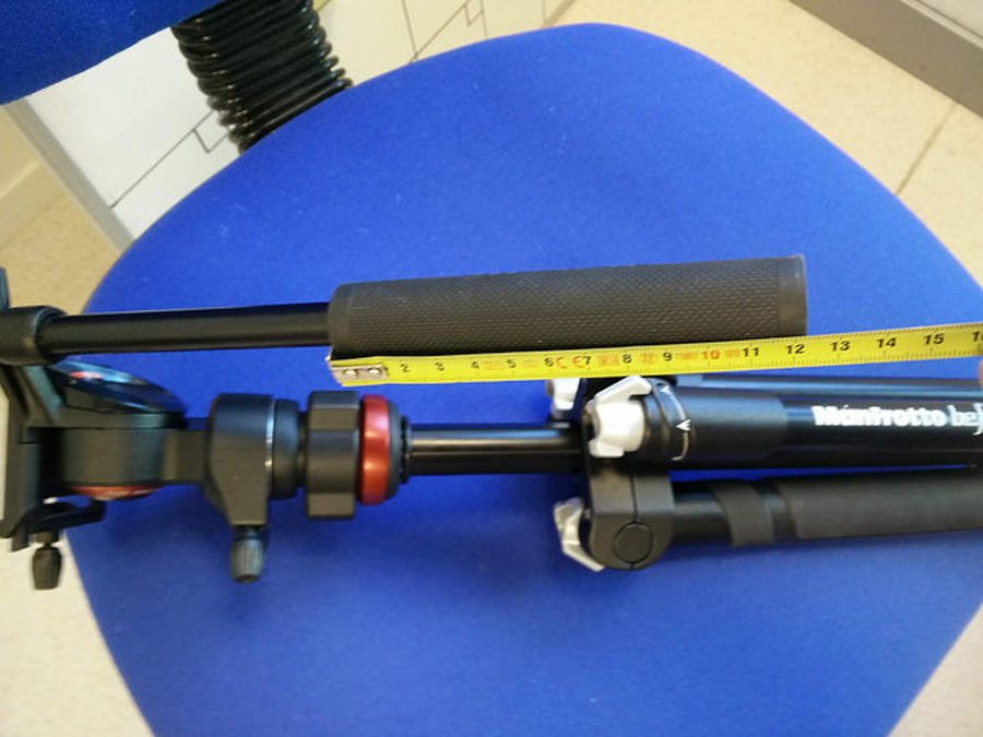
I looked at sizes of Coke bottles, as in the triange game video. The video appears to show 1.5ml bottles being used in the game. Aesthetically, I am in interested to create a wider, taller devices that is visible to spectators at a greater distance. However, if the devices are too big, they are to easy to play round (extreme eg. passing between three tree trunks). There is also the issue of the 3D printer: The maximum height for printing on the Ultimaker 3 is 215mm.
This is a crucial constraint because I am still aiming for a slim design – One which will topple with a medium amount of force. I think this is important for feedback and also reflects the real nature of a football game, ie. If the buoy was a player, you would have passed the ball to the opposition.
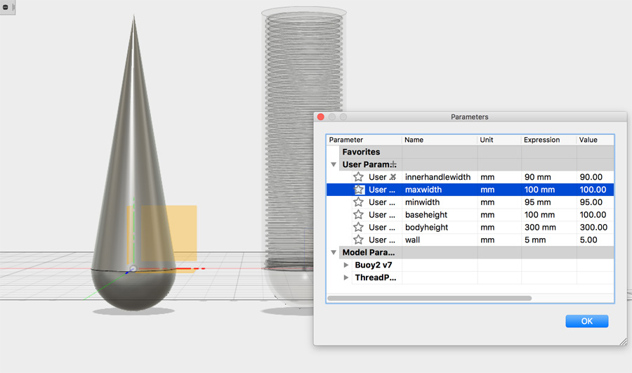
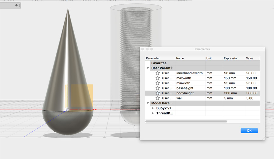
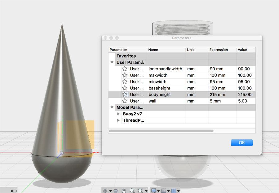
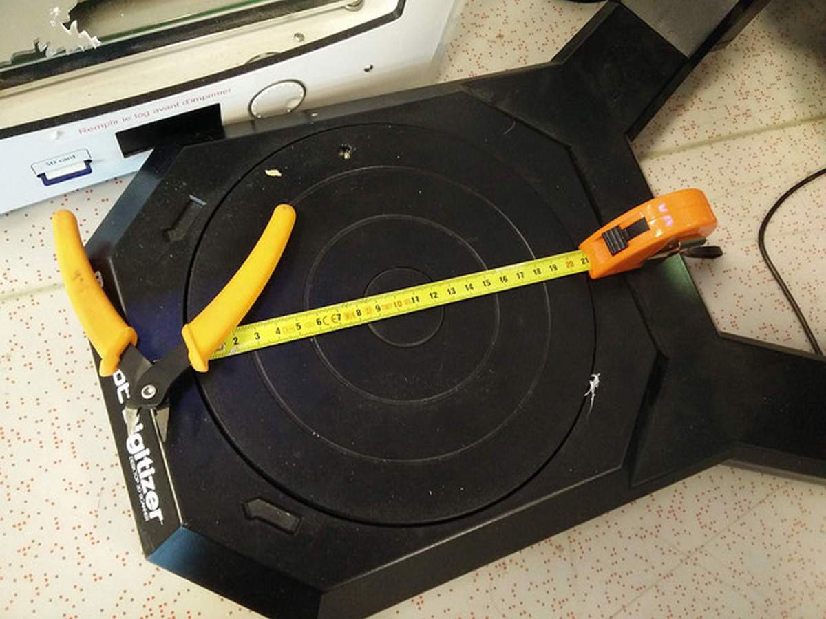
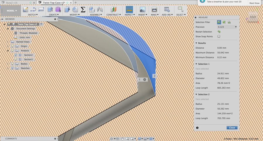
The screenshots above indicate the subtle variation in height has a huge impact in the buoy's width and therefore it's stability. The issue is with the height of the top body, but the base width is naturally affected. It was useful to compare circular widths on a Shopbot turntable in the Fab Lab.
I potentially have access to an Ultimaker 3 Extended, which would raise the maximum height to 300mm. There is also the molding and casting route – I am aware that mixing materials could offer a durable finish, highly appropriate for outdoor use. The time to print three, very large buoys on a 3D printer would be very high. Perhaps the best way to proceed is to print one buoy with the Ultimaker 3 and use this to create a mold to cast from.
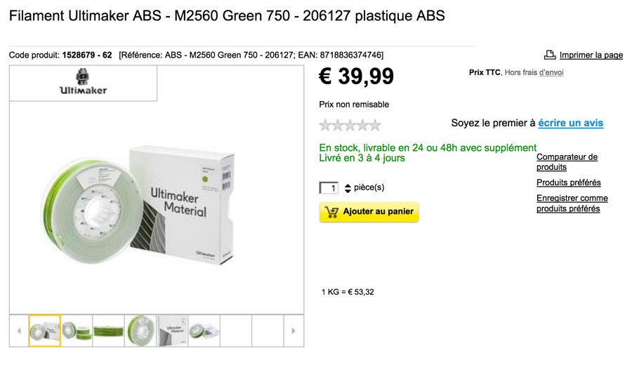 image source
Another aesthetic decision - What colour should it be? I am considering green, but of course, if I want green lights, I will have to adapt this. Hypothetically, the whole buoy could light up. With thin material and a bright light, it could light up just like a bulb. But as I am looking to use fairly sturdy material, I may have to create a light externally.
The buoy has a handle for easy transportation. I spent time considering the appropriate width – The minimum for an adult (90mm) would be an acceptable maximum for a child. This will be a key change to how I drew my concept: I can't create a (triangular) shaped handle on such a small buoy, unless I position the handle lower or change the triangular shape of the buoy.
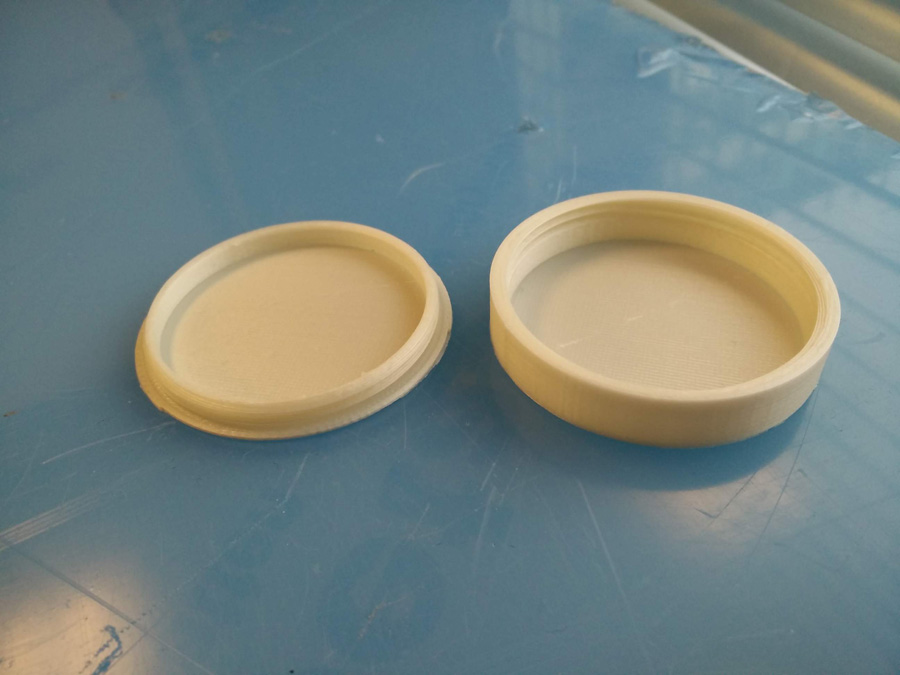
I knew I would need some sort of mechanism to connect the two parts of the device – A base to hold the counter weight and electronics, and a body/cover holding lighting. A screw thread seemed the natural choice for connecting the two, and this was complex enough that it could not me made easily with 3 axis limitations.
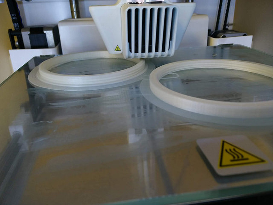
I worked with the thread tool on a simple cylinder shape, before progressing to a thread on the buoy parts. Based on two circles, I thread the outside and inside of an extruded part. When I text print this, the parts did not join because there was not tolerance between them.
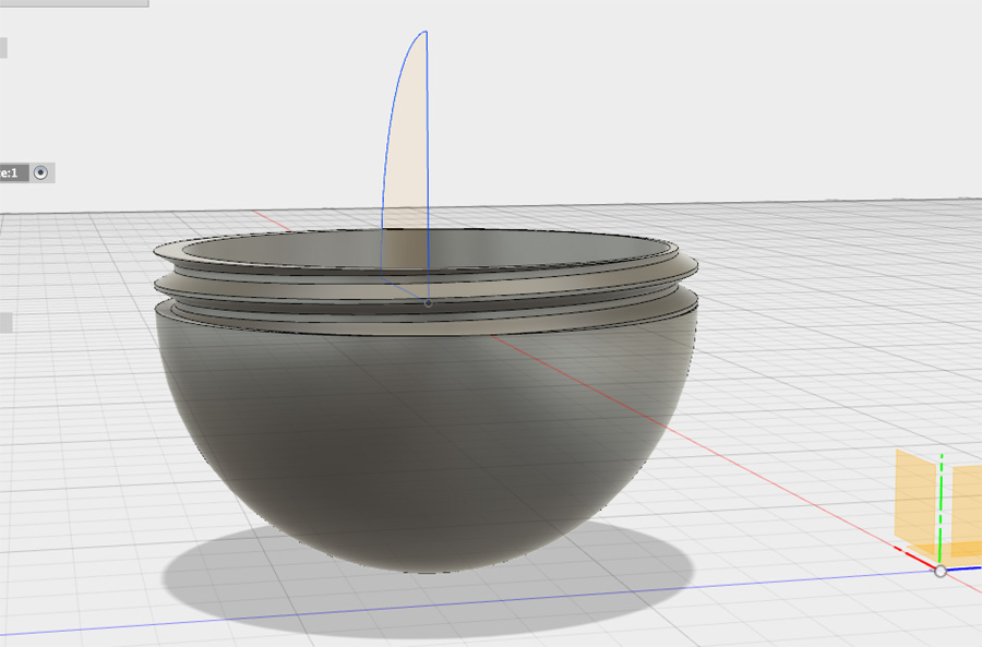
I parametrically in Fusion 360, based on my sketches and measurements. I created a simple hemisphere and cone structure, this time in a more efficient way – Using the sketch of a quarter circle and triangle. These sketches were then extruded using the Revolve tool. I gained this technique from a screencast on the Autodesk site.
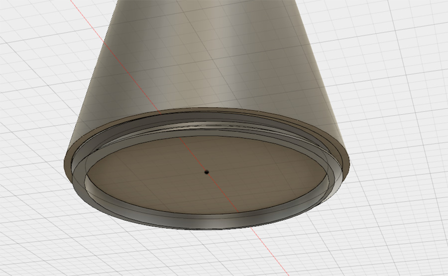
I referred back to my original little pen. On closer inspection, the thread is made up of an additional on the rim, which is extruded with a thread. This means that when the pen is screwed together it is flush. I would like this characteristic in my design and set about matching the face/extrusion. I reviewed a great video about split face but found that I could achieve my design through an additional circle sketch.
It was at this point I started to get bogged down in circles – I was attempting to reuse the same circles in the base as in the top body. This would mean there would not be any tolerance. Also, I found while jumping up and down in the design history, I lost some of my work. I felt at this point it was important to do a tutorial which would give me a complete understanding of threads and tolerance.
I continue my final project work in week 14.
Group Tests
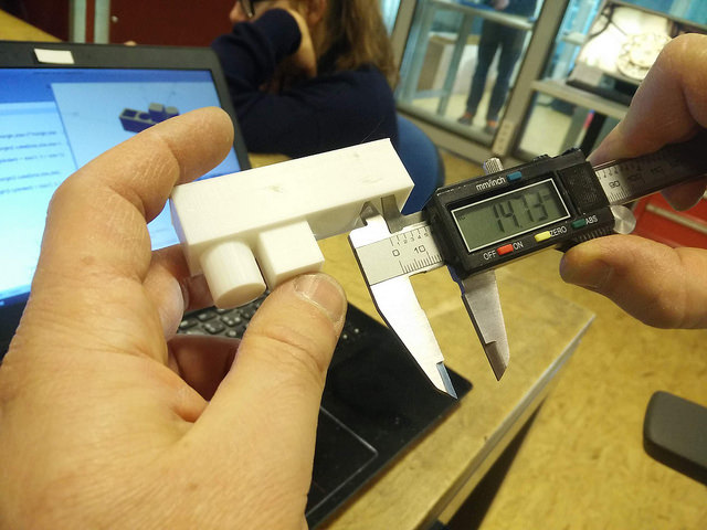
With Thierry and Adel, we printed a couple of objects to test the accuracy of the Ultimaker 3. The first test Thierry created a simple series of extrusions and pockets that we could compare with the caliper. For the extrusion, we found a difference of 0.2mm between the set and printed dimensions. For the pocket, there was a difference of 0.3.
In the second test, we used the 3D Benchy boat to compare different materials, ABS and Polycarbonate. We found a similar level of minute variation between the two materials.
My final print for this week is therefore a combination of all these learning: Using internal and external threads, creating an additional sketch circle to allow appropriate tolerance for the parts to fit together.
3D Scanning
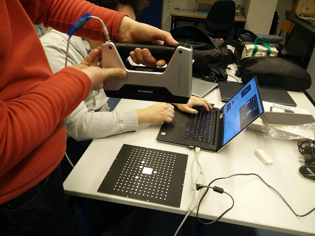
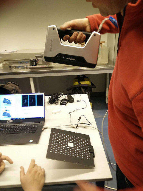
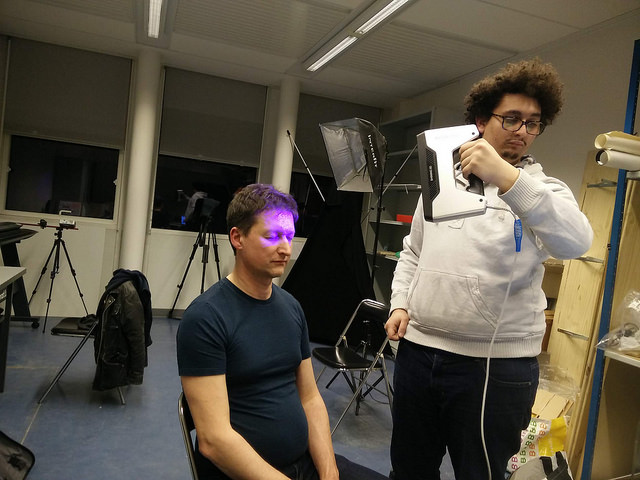
We chose to use the Shining 3D EinScan-Pro, a hand-held device. The scanner requires significant manual calibration. The calibration is conducted by holding the device above a pad covered in dots and moving it vertically upward.
As you work through a range of different angles, a blue crosshair emitted from the 3D scanner must be kept perfectly in line with the middle of the pad. Some angles require you to raise the pad on a plastic support to vary the angle. The software gives feedback with a bar which turns from orange to green when the device is properly calibrated.
On starting a new scan, you choose between 'HD' and 'Rapid Scan'. Knowing the complexity of scanned models, I chose to work with Rapid Scan. There are two additional settings: 'Fix Scan' for tripod work and 'Free Scan' for work done by hand. As a group, we used Free Scan for our early tests.
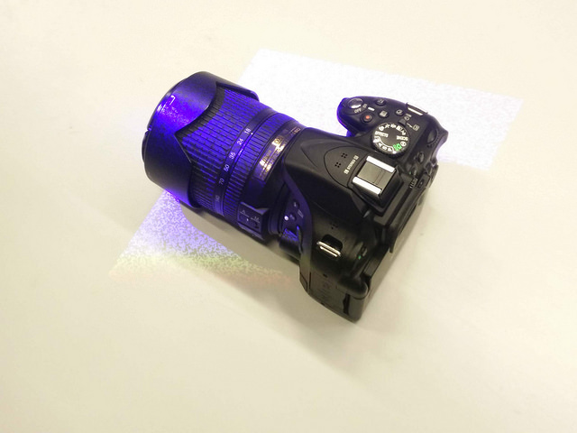
We started by scanning Thierry's camera, which we thought would be a relatively simple task. Positioning the handheld device without leaving gaps proved challenging – Move to fast and the software grinds to a halt. You must recover your position to somewhere the scanner has already analysed. We found we spent most of the time looking at the screen, rather than the object being scanned. The best technique was to move slowly, but despite our best efforts, several crashes caused us to lose information mid scan.

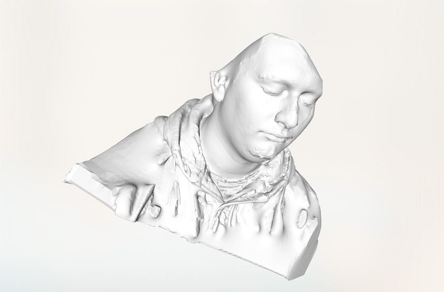
I chose to scan Adel and focusing on his head and face. Adel was in a seated position and I moved the scanner and cable around around him in as fluid a way as possible. There were challenges with software stalling and, on one occasion, crashing. The second time I move slower and paused anytime the software stalled. Although the software was not able to scan his hair, it did a good job of capturing his face and clothing. It certainly picked up the detail of clothing very well.