TASK TO DO:
- make something big
- Explain how you made your files for machining (2D or 3D)
- Shown how you made something BIG (setting up the machine, using fixings, testing joints, adjusting feeds and speeds, depth of cut etc.)
- Describe problems and how you fix them
- Include your design files and 'hero shot' photos of final object
- Test runout, alignment, speeds, feeds and toolpaths for your machine
- Explained how I made your files for machining (2D or 3D)
- Shown how I made something BIG (setting up the machine, using fixings, testing joints, adjusting feeds and speeds, depth of cut etc)
- Included my design files and 'hero shot' photos of final object
- Both Guide ways (i.e X and Y) are parallel. Check the bed level by using bubble levellor and then sacrificial layer fixed using screws.
- Speed is directly control by VFD(variable frequency drive).
- While installing check the alignment and ensure about this by moving tool and cutting one job.
- Spin around 18000rpm but they operate on 12000rpm. We are using partworks 2D but partworks 3D also available.
- Machine controller software guide the hardware of the machine.
Group assignment:
WHAT I HAVE DONE:
What is machining :-
Machining is a removal of material from solid bloks or workpiece for manufacturing the objects. It has several processes cutting, drilling, forming, grinding, milling,etc.
About CNC:-
This is Computer controlling machining week in which we have to learn CNC machines like shopbot.
CNC stands for Computer numeric control which translate programs consisting of specific numbers and letters to move the spindle (or workpiece) to various locations and depths. CNC mills can have 3 to 6 axes. Most CNC Mills require placing your workpiece on or in them and must be at least as big as your workpiece, but new 3 axis machines are being produced that you can put on your workpiece, and can be much smaller.
Why is CNC Machining necessary?
CNC machine operators work in a wide variety of fields. People from all different pursuits, such as hobbyists and even military groups, take advantage of the cost savings accrued by using CNC machines to turn raw materials into final products. The machines are faster, more efficient and safer, too.[Google]
Designing and Prototyping :
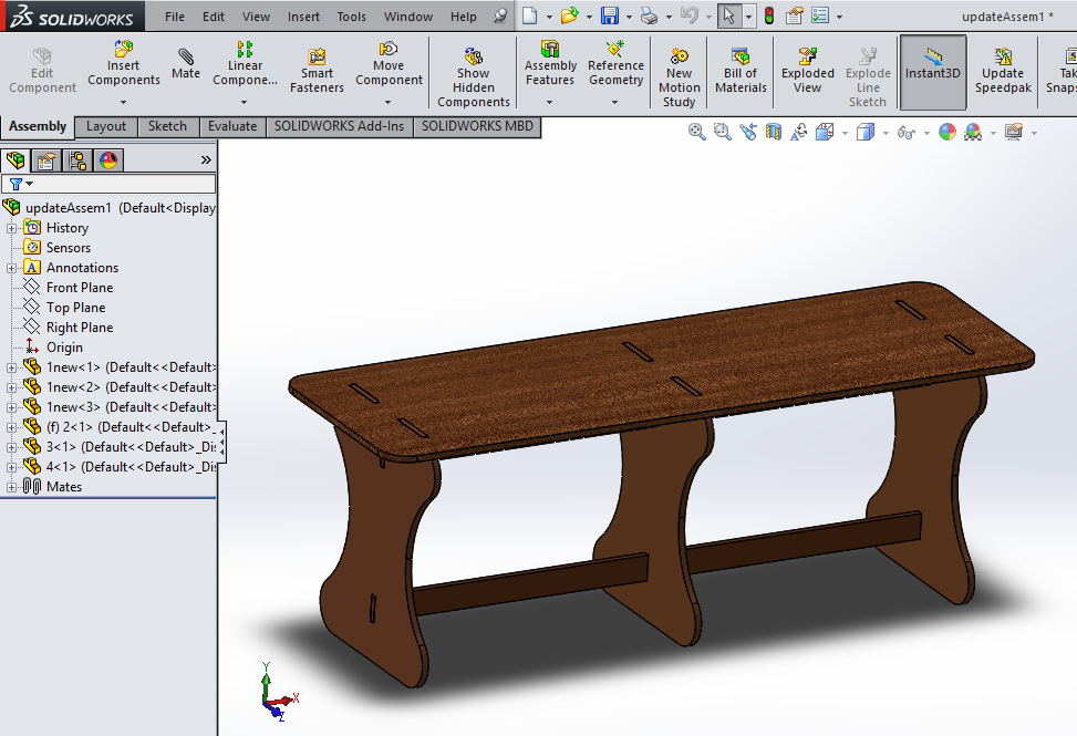
This assignment is all about make something big. So, I decided to make sitting bench. I started with different ideas like standing desk, thread stand, chair,etc. I finalize the sitting bench.
I draw rough sketch of sitting bench on paper with dimensions. Skteching on the paper is very useful and important for designing. There are very few parts i.e. 3 foot, seat plate and supporting material. I will use 12mm plywood for this.
I started with designing parts in solidworks, First I designed foot part of bench has width, height.
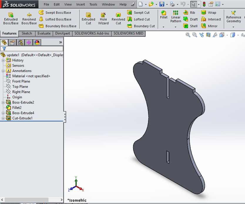
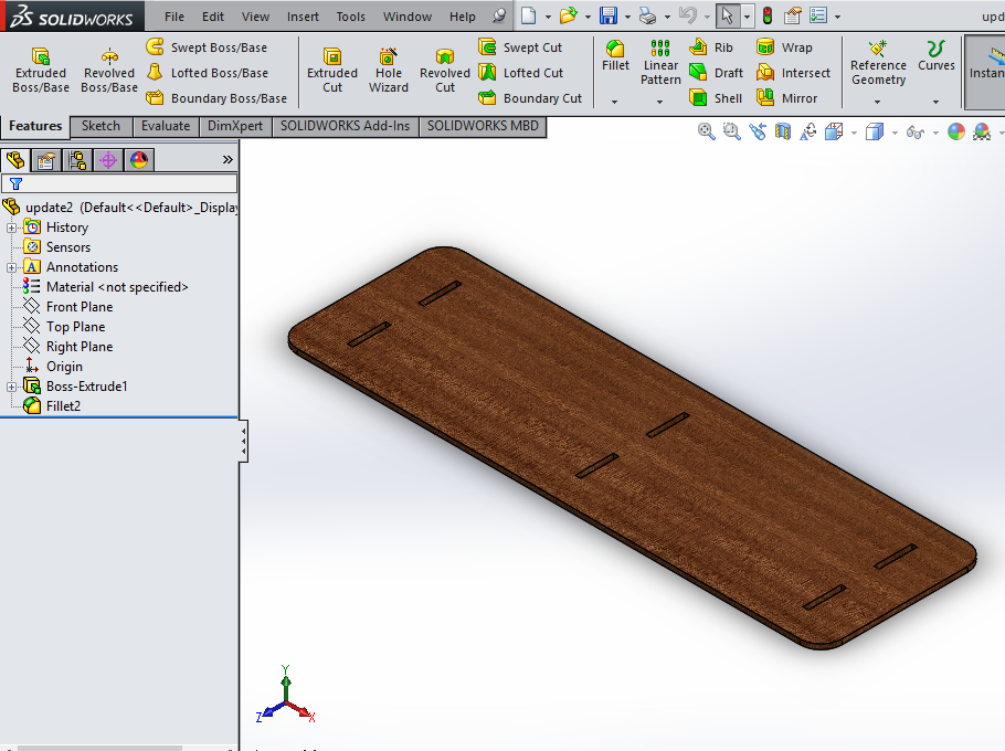
Then I designed top part of bench and then two supporting plates.
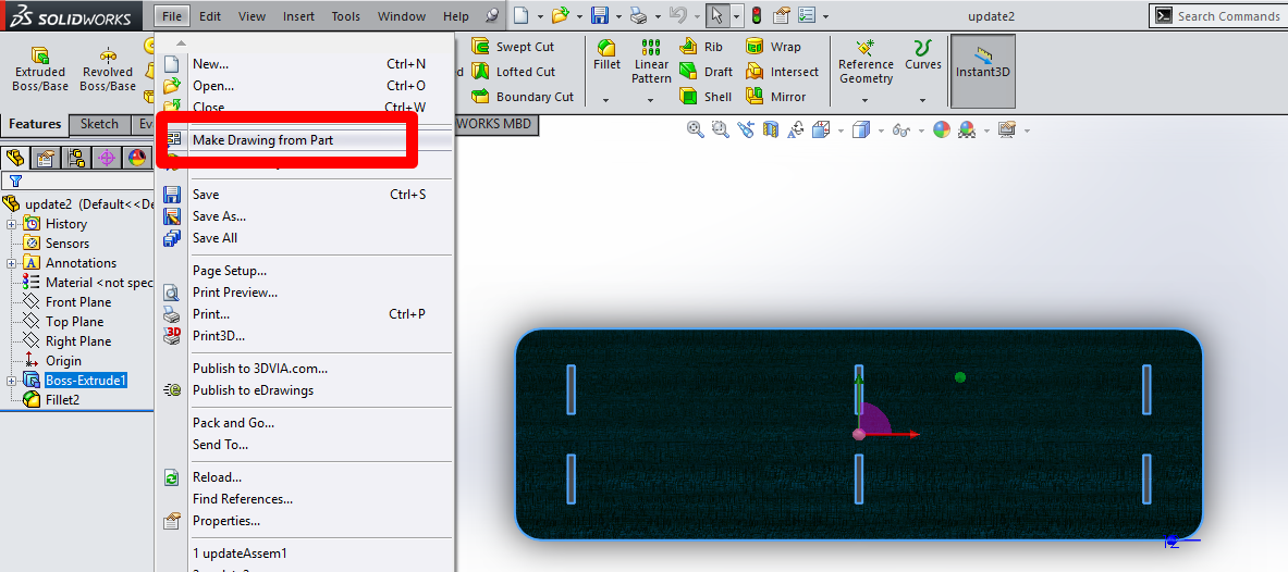
Save file as pdf (Solidworks) :-
step 1: Click on the part and make drawing from part.
step 2: Then edit and save the sheet size by selecting the custom size.
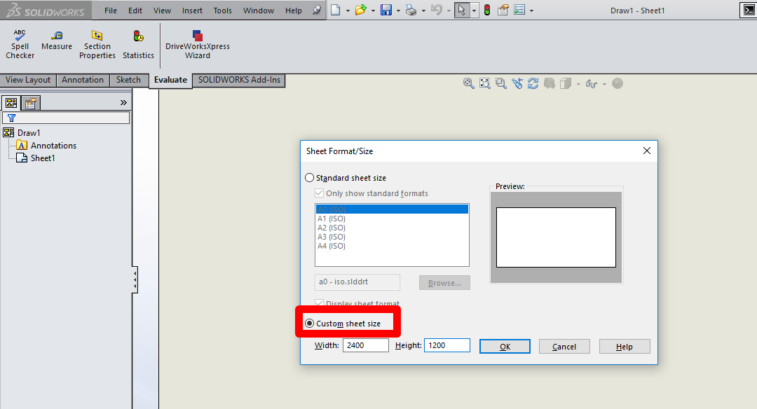
step 3: Drag the part which we want and select the custom scale i.e 1:1.
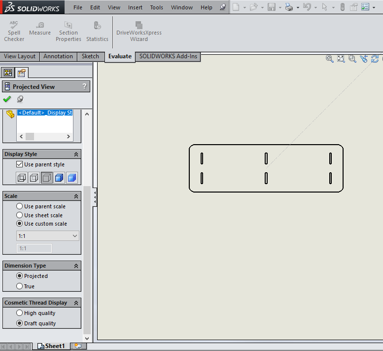
Step 4 : Then save as .pdf format.
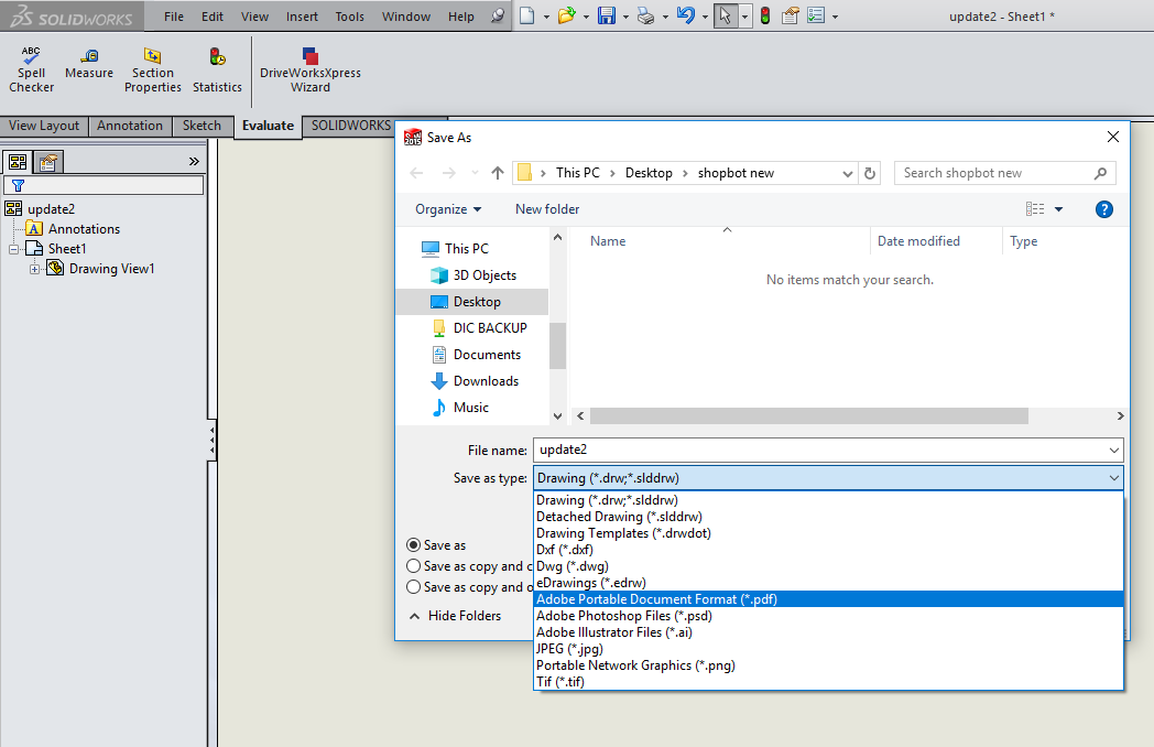
Here my design is ready for cutting.
CNC Routing :-
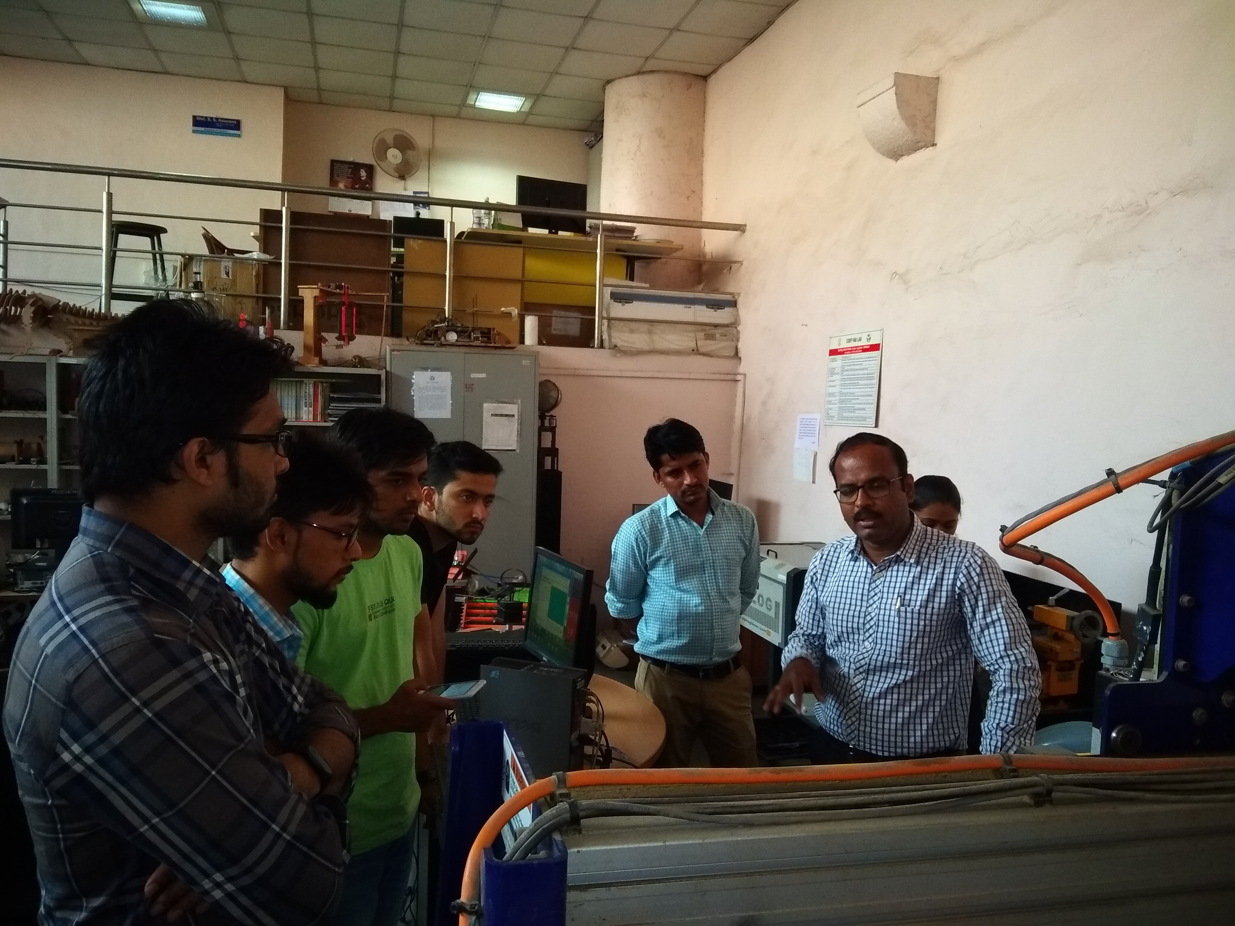
At vigyan ashram we do not have a CNC machine, thus we had to go to college of engineering, Pune. In that college, shopbot was available for us.
We were introduced to shopbot machine working by Mr. Anasare sir and his M.tech student Bhushan when we visited to their fablab.
About Machine:
The shopbot machine at COEP is a 2.5 axis which runs on 230 volt supply. It has 8'*4' standard bed size and able to cut wood and plywood. It has guideways in X, Y axis and a router is at the z-axis which is capable to spin 12000 rpm. We are using end mill as a cutting tool for this machine.
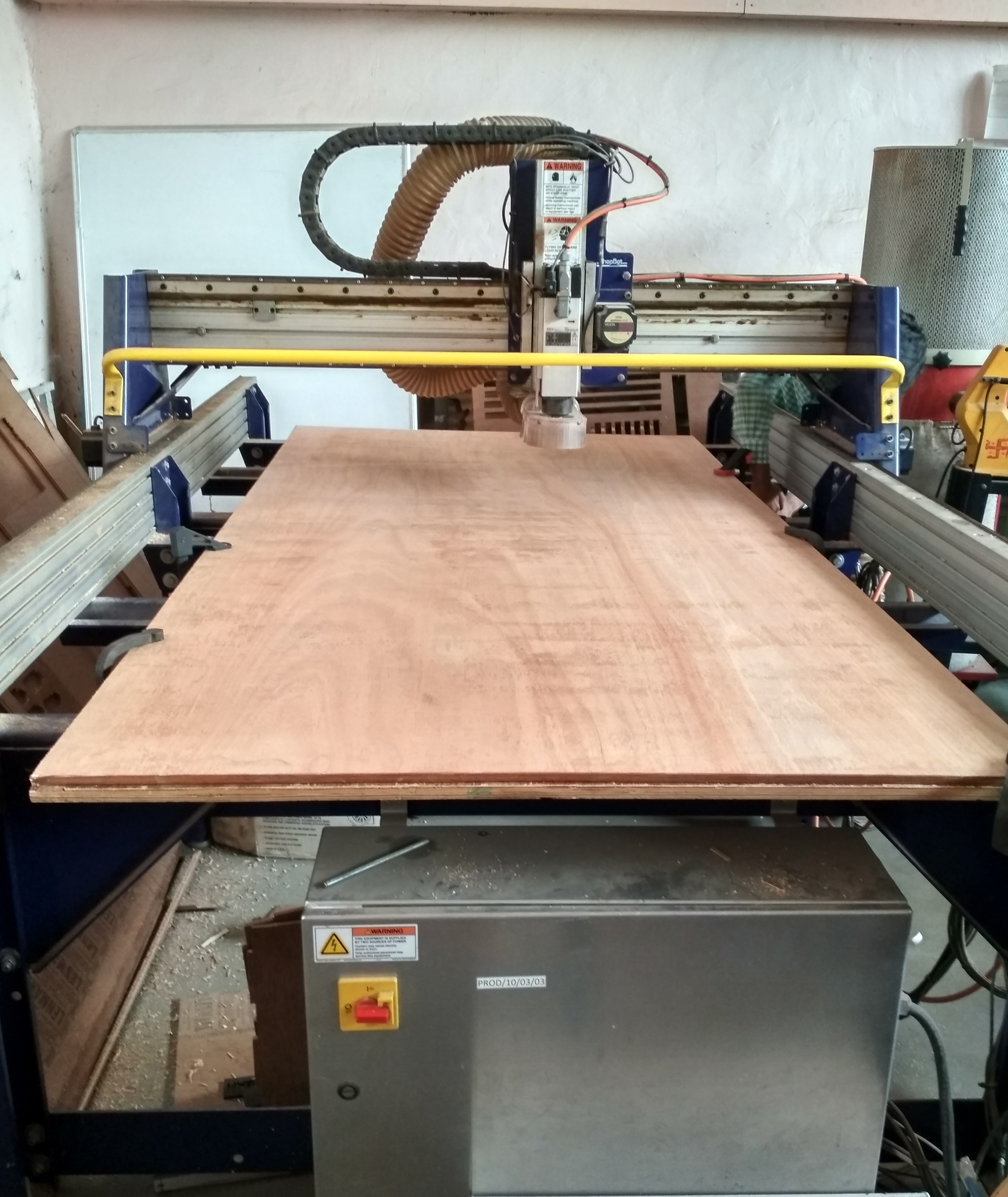
Scarificial Layer -
Shopbot machines bed made up of metal and to protect this bed we have to place flat layer of the plywood on the metal bed which is the sacrificial layer. In case the endmills plunges more than the thickness of the material it will cut into the sacrificial layer, so for this Sacrificial layer is important. While cutting our main part is placed over the sacrificial layer and clamp it.
Group Assignment:
For the group work, first of all we get information about shopbot by coep instructor. He shared his experience about installation of shopbot machine with us.
Some points while installing the shopbot:
Below things plays an important role:
1. Plunge rate - It is also known as stepdown, it is the distance in the z direction per pass that a cutting tool is plunged into the material
2. Spindle Speed - rotational speed of the cutting tool in revolutions per min
3. Step Over - the maximum distance in the x/y direction that a cutting tool will engage with uncut material
4. Feed Rate - Surface speed at the center of the rotating tool
CHIPLOAD-
Chip load is the thickness of the chunk of material taken by a tooth of the cutter.
Chip load is a function of three different parameters: feed rate, RPM, and number of flutes on the tool.
Formula for chipload-
Chip load = Feed Rate / [RPM x number of flutes]
When chip load is too small, bits will get too hot and dull quicker. When chip load is too high, the tool
will deflect creating a bad surface finish and, in extreme cases, chip or break the bit.
For wood, general rule of thumb is to always make pass depth 1/2 the diameter of the tool. So in this case of a 0.25" (1/4") end mill, The pass depth should be to 0.125" (1/8").
We know this, still you can see that the Pass depth is more than the tool diameter, We tried to convince the administration at COEP, but they were adamant on their parameters.
For group assignment we have to check the alignment, spindle speed, etc.
1. Bed Alignment- The most important thing is alignment i.e we have to check the bed level. If alignment is not proper then it will damage to bed and drill bit also.
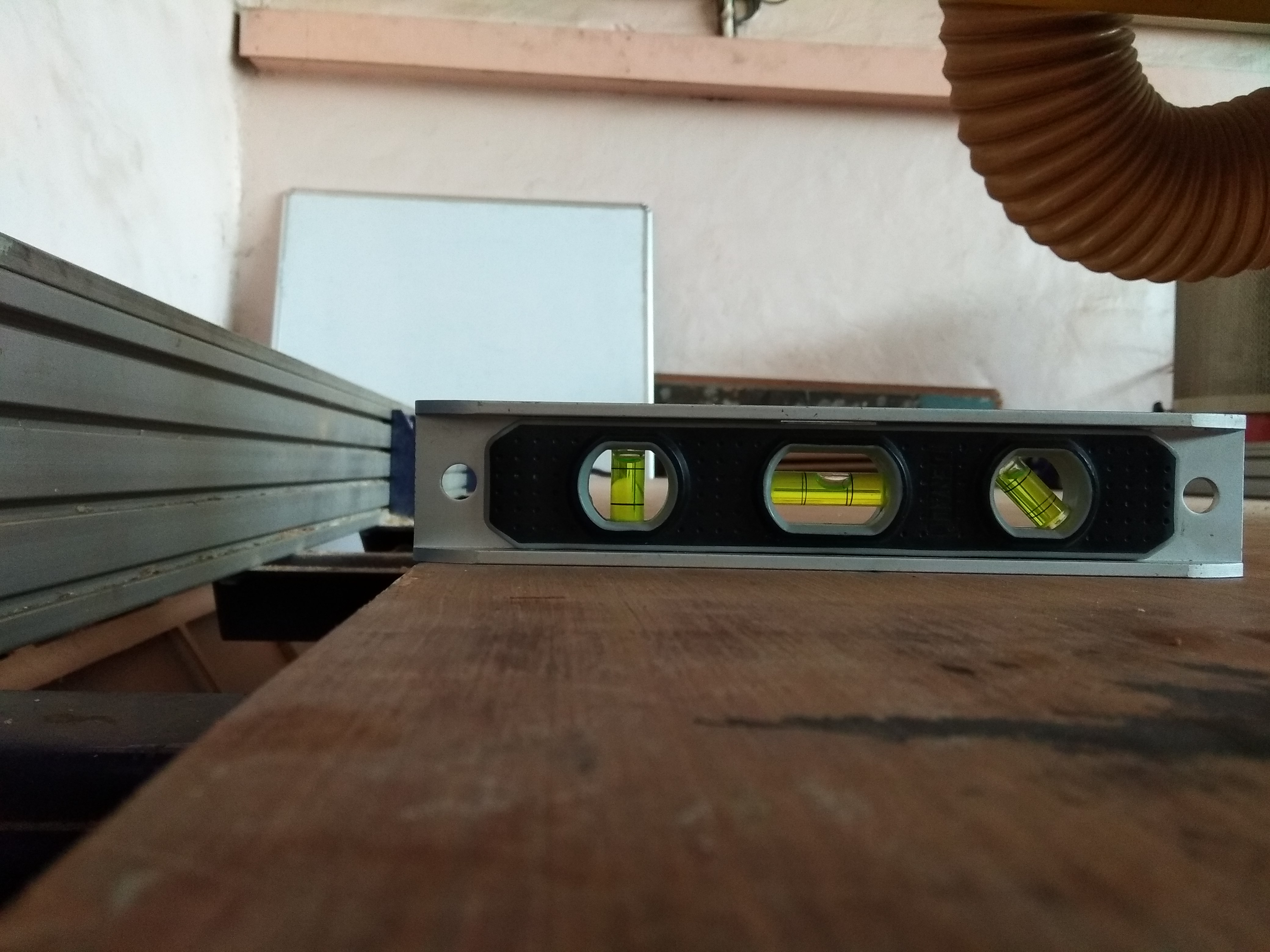
We found bit of slant while checking the alignment. But we don't have permission to do the bed alignment. (As instructed, since if any things go wrong its technically difficult to get help in India.)
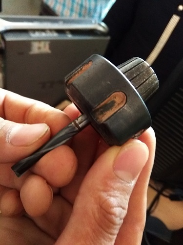
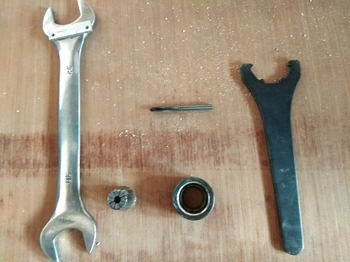
2. Tool Alignment -
There are two main parts in tool assembly:
a. Collet
b. Shank and the nut that tightens the collet.
Images as shown below.....
How to remove the Tool?
Initially we loosen the screw of vaccum duct which is behind the z-axis. Then with the help of a special groove spanner loosen the nut from the shank.
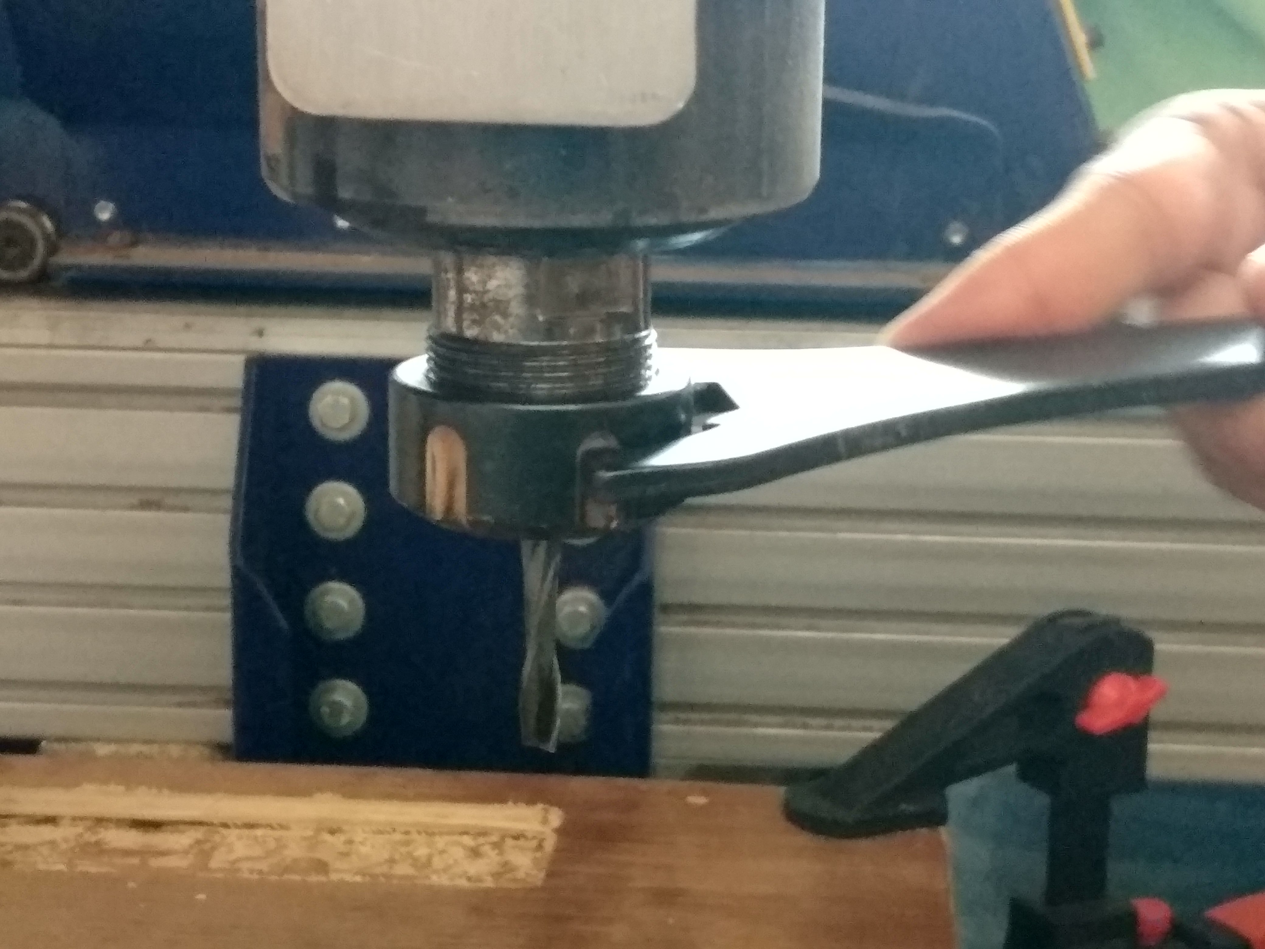
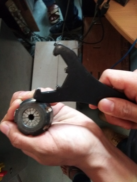
After this remove the collet and tool, change the tool and re-assemble the collet and fix the tool to machine. This is our tool assembly...
Spindle Test:-
We made test part to check the dimensional error and finish while varying the speed and feed rate.
We got our test parts and they look like this...
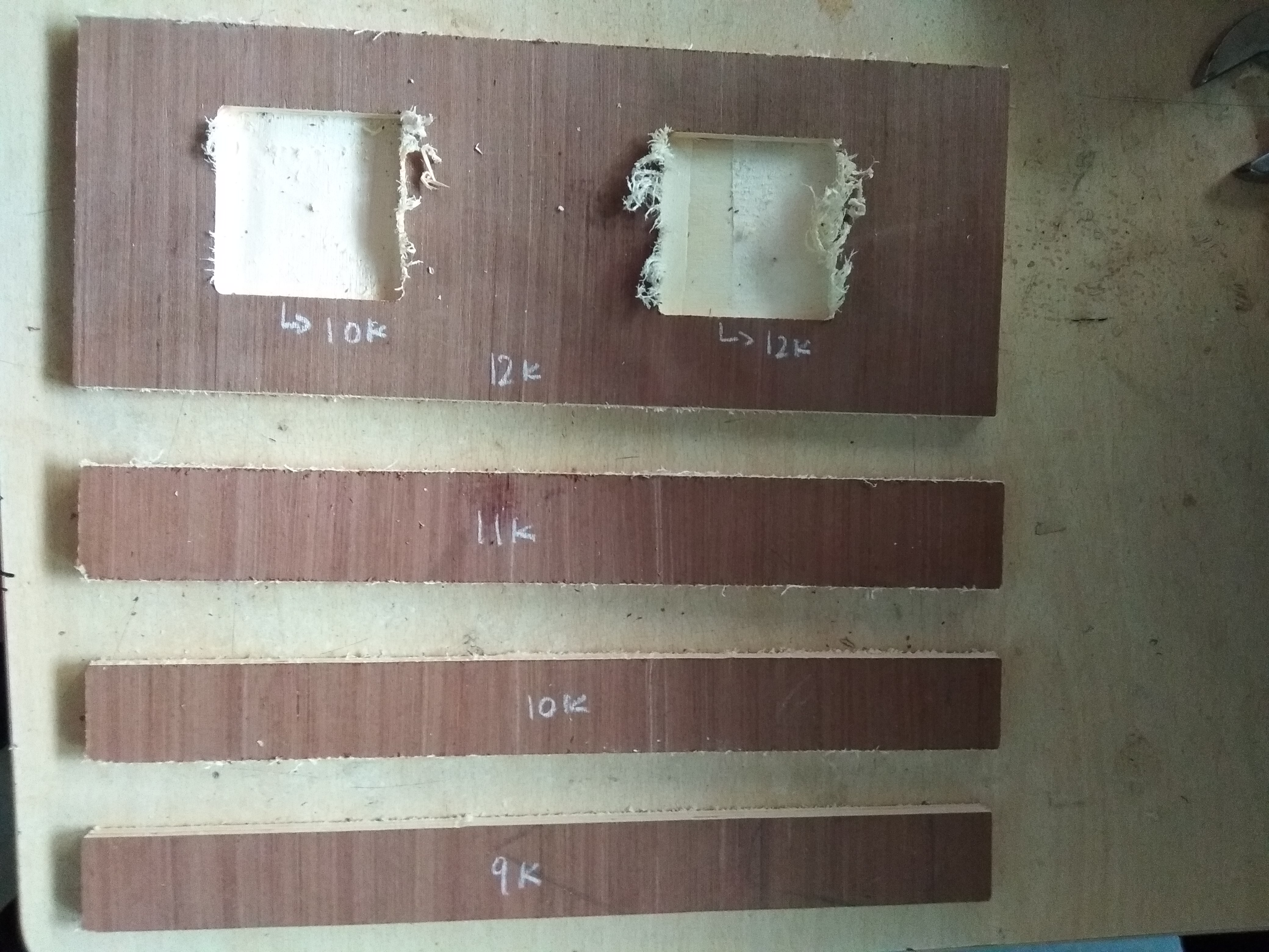
For this results we concluded some points:
1. We cut some slots with 40mm thickness and we got this results which shows below:
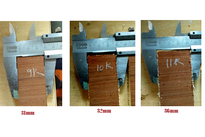
We can see clear results i.e lesser the speed, greater the error. Hence we decided to keep 12k RPM speed which is the standard spindle speed.
2. Here we got results for pockets as shown below:
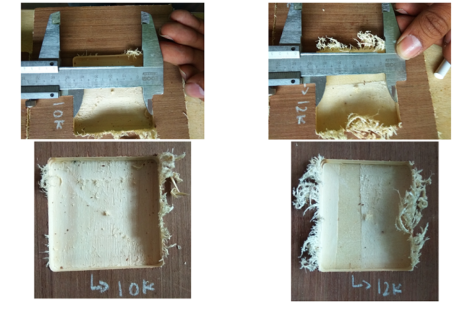
We can see that the speed of 10k had a better finish as compared to the slot milled at a speed of 12k.
Machine Software :
For cutting any part on the machine, we used two software i.e. Partwoks as a editting software and Shopbot editor as a machine software.
1. Partworks -
For the partworks, we have to save our parts in .dxf or in pdf file.
So we started with one small part for calculating the kerf and it is 1mm in my case. So, I made changes in my design files.
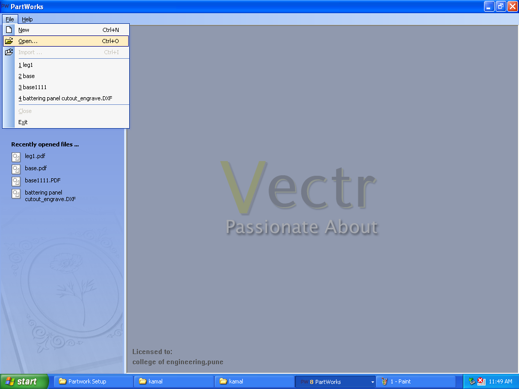
In partworks I clicked on the open file option rather than new file.
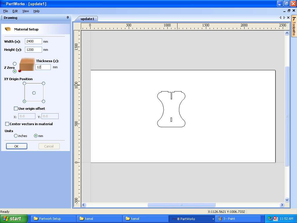
Set the width, height and thickness of the sheet. In my case width= 2400mm, Height= 1200mm and thickness= 12mm
Then join the vectors because machine not accpeted open vectors. (For this, select the all lines by using shift button and click on join vector option).
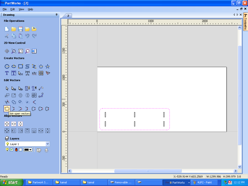
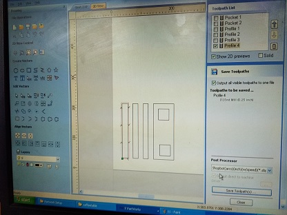
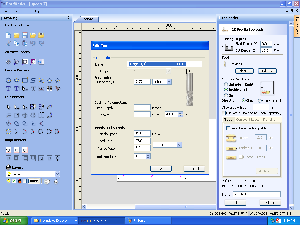
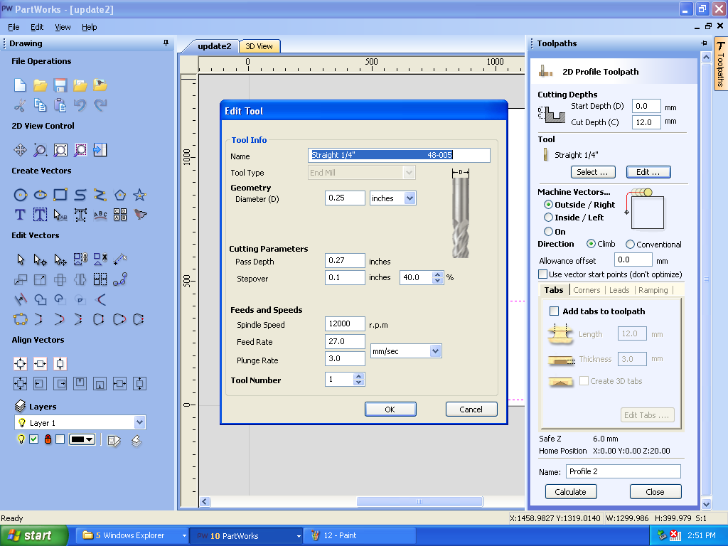
Toolpath:-
There are two toolpaths one is the pocketing where the endmill cut the inside part of the path it traverses and other is the profiling where the endmill cuts the outside of the path it traverses.
My design had both profiling toolpaths. Save and check the tool paths.
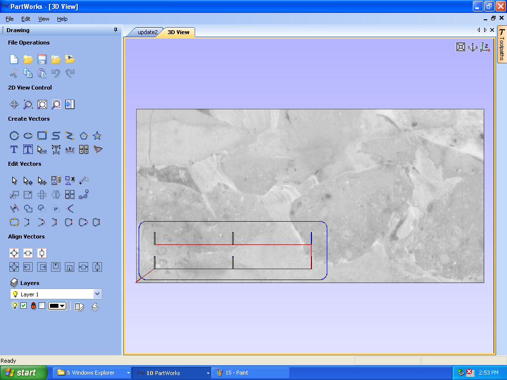
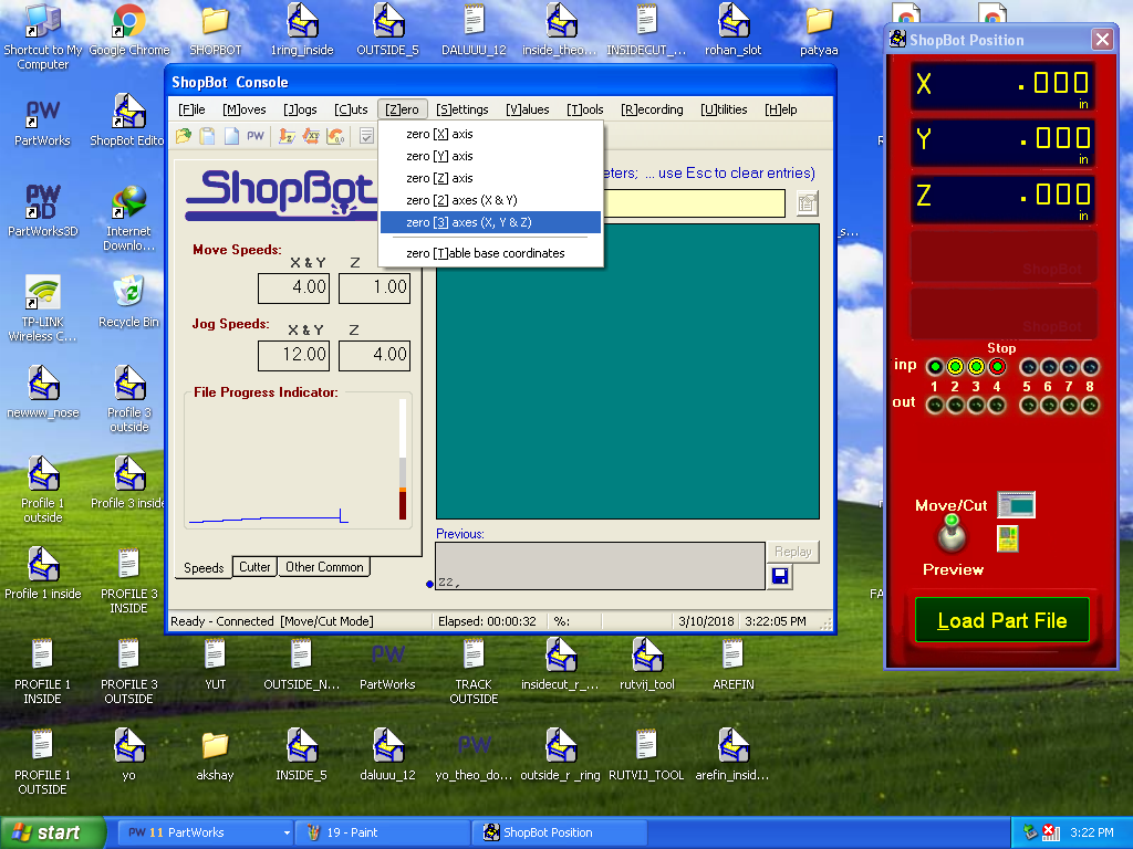
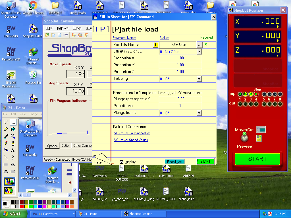
Then open the shopbot editor software and click on preview button. One window opened in which we can fix the shopbot machine position. We have to set all three axes at zero position.
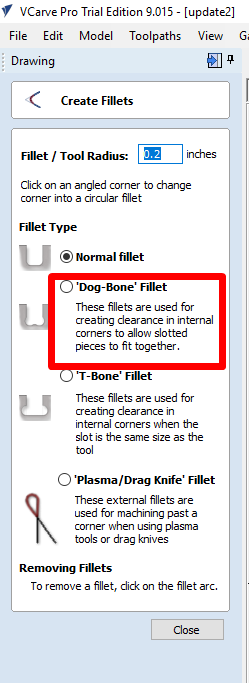
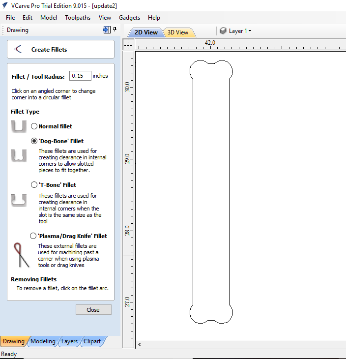
While going through evaluation, I came know about Doggy bones. Dogbone fillets are used to overcut into a corner when the application of the part you are making needs to fit tightly with another.
A known problem is that while the CNC can make a perfect outer corner, the inner corners can never be more sharp than the diameter of the cutting tool.
How to fix Dogbones in Vcarve?
Download the Vcarve.
1. Open the file (PDF format) in V-carve.
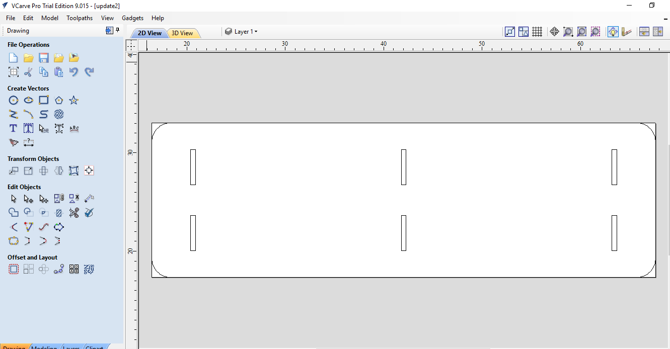
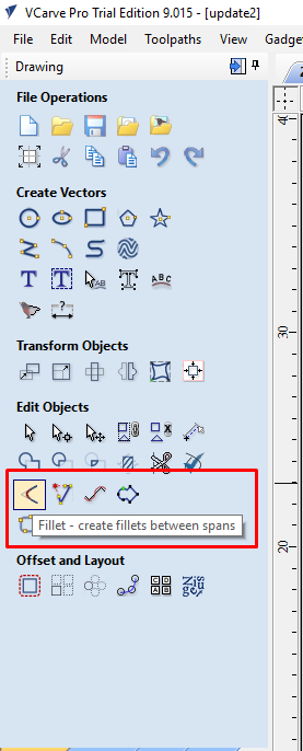
2. Select the "fillet" option.
3. Then select the Dog-Bone fillet option.
4. Then move the cross onto corner YOU NEED TO BE REALLY ACCURATE AND SEE THE GREEN TICK APPEAR, THEN YOU CLICK AND IT CREATES THE FILLET.
Then save the file.
Start The Machine -
Before starting the machine work we have to follow some precautions as follows:
1. You have to wear all safety things i.e apron, shoes, ear protection, gloves and eye protection. This things are very important.
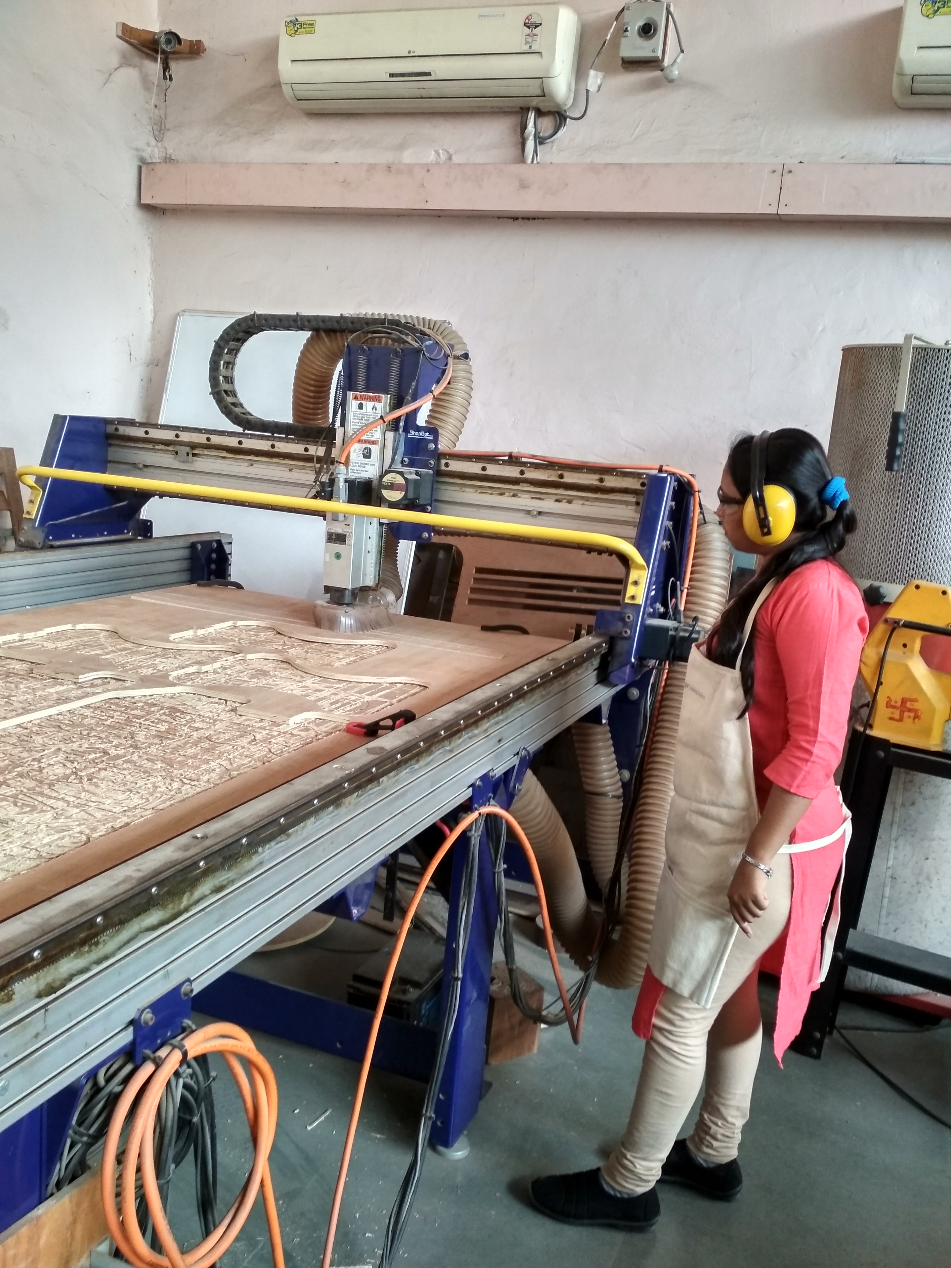
2. Turn ON the vaccum which sucks all the dust generated during cutting of the wood.
3. Another important thing was to ensure the tool is above the bed cause if the releasing of the emergency switch trigger the spindle(usually doesn't happen), then it might break the tool.
After this load your part file.
Check the all things. I clamped the wood sheet which is on the sacrificial layer by using C-clamp.

Then finally turned ON the machine and Cutting started.
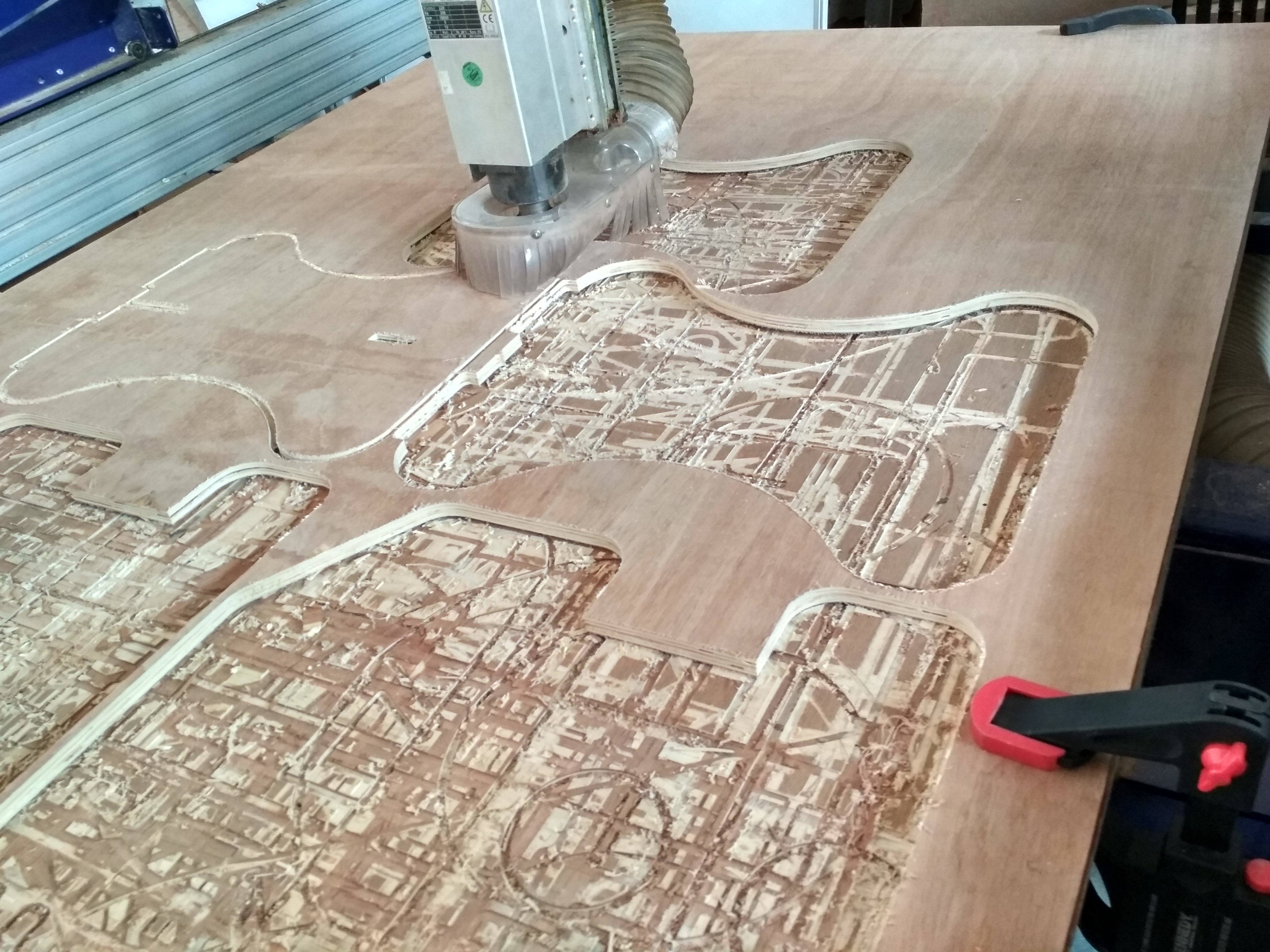
These are the parts of sitting bench.
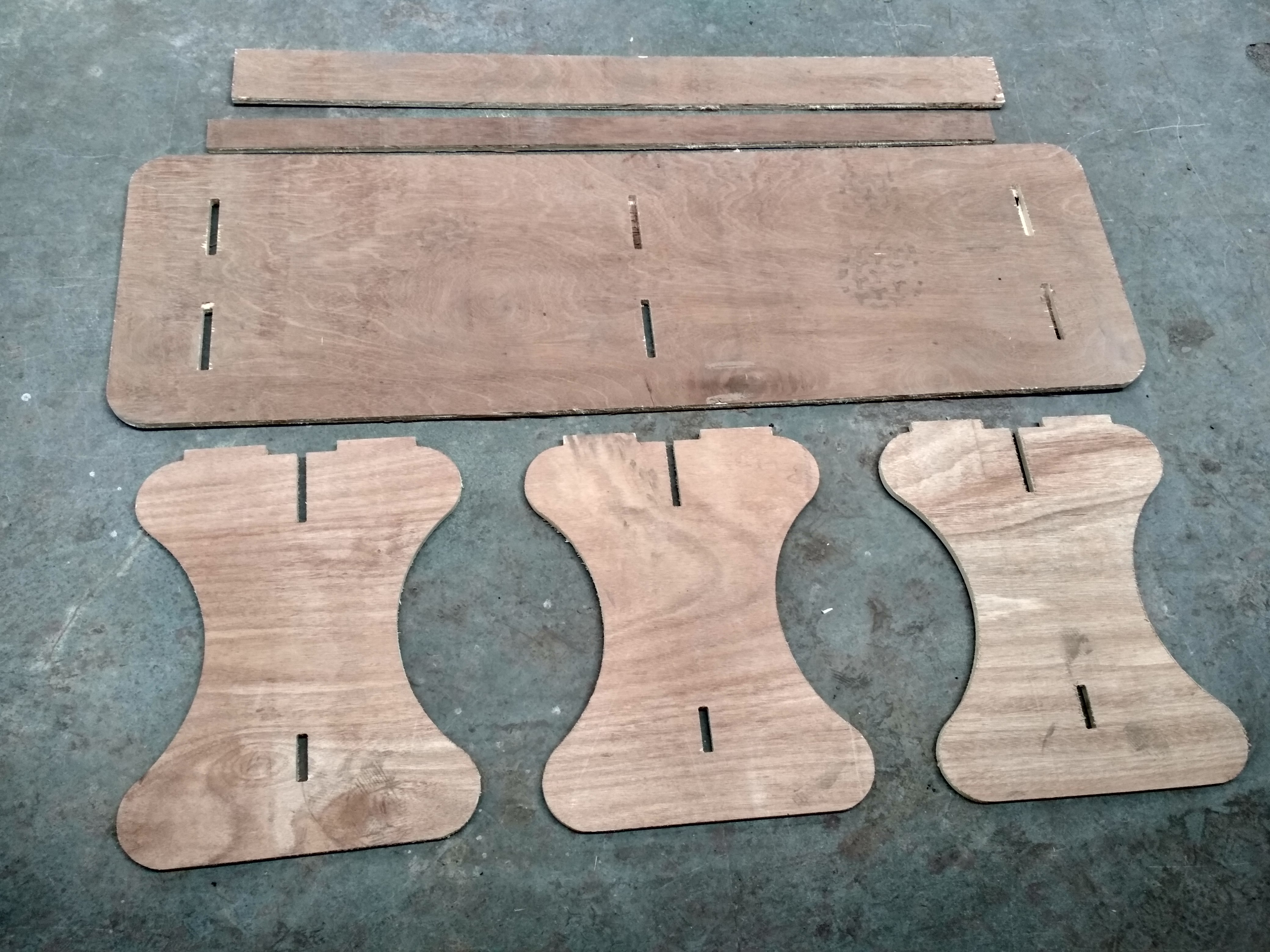
After cutting I assembled the Bench and its really looking nice and press-fit.....
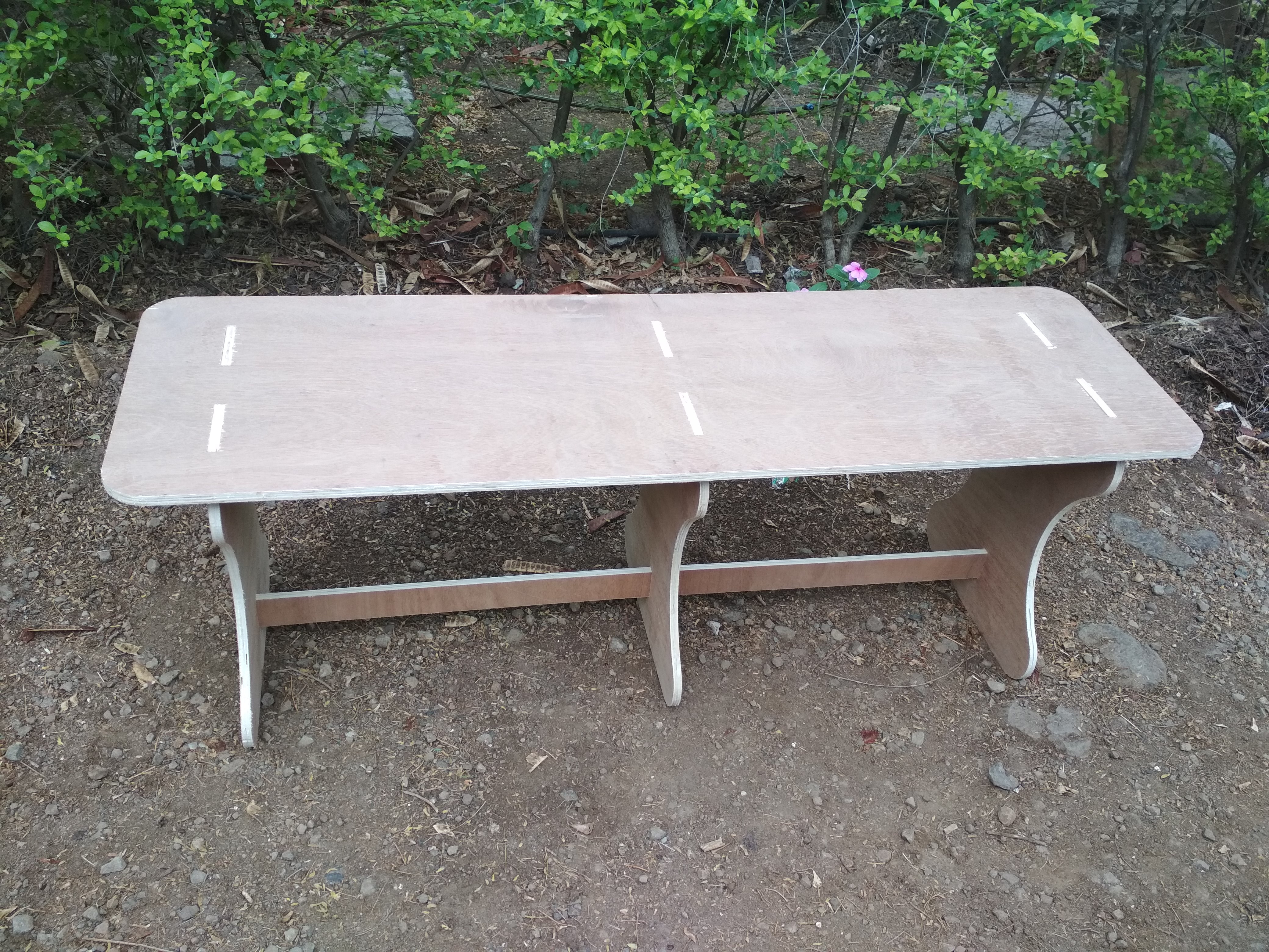

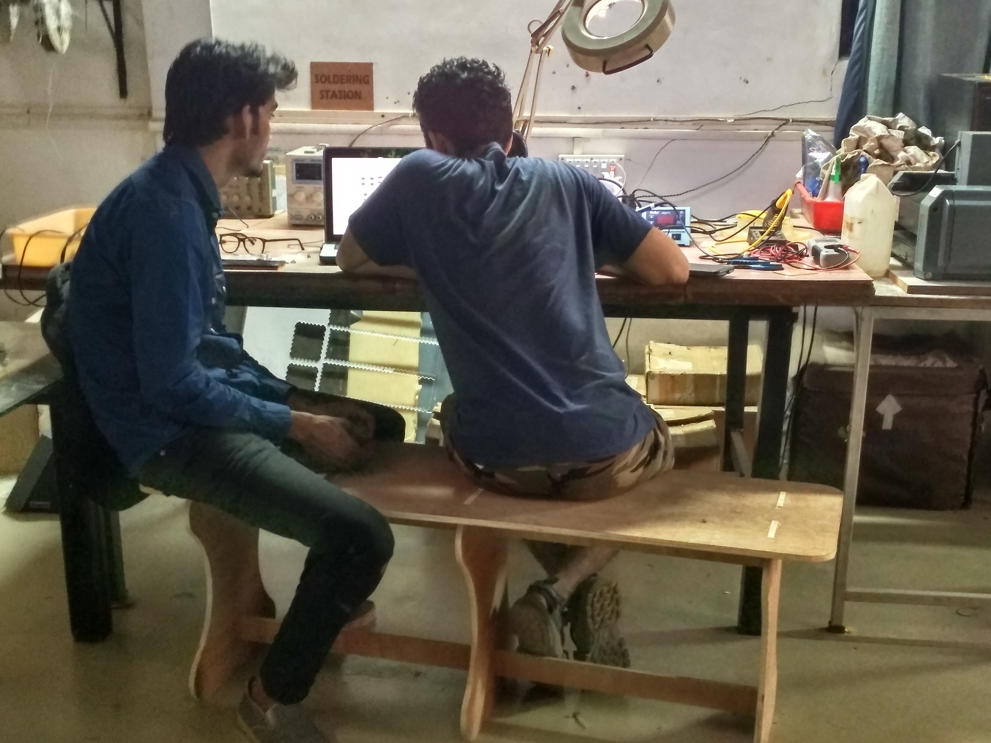
Now, this sitting bench included in soldering station..for sitting purpose..
You can download partworks original file from here.
You can download solidworks original file from here.
Learning Outcomes -
This assignment was really very nice. This is awesum feeling to make something useful from scratch...Your idea and your design...infront of you people used it. From now I would like to design any furniture as I want.