This week, we worked with the 3D printers in our lab: learning how they work, testing their characteristics when printing various difficult topologies, and designing and printing an object that's impossible (or at least very hard) to make with substractive manufacturing processes. In addition, we tested the 3D scanner available in our lab.
Substractive vs. Additive Manufacturing
The process of substractive manufacuring takes away material from the object, while additive manufacturing successively adds material to the object. Substractive manufacturing has been around longer, and is usually faster than additive processes. Thus, it is often used for high-volume production. Additive manufacturing, on the other hand, can produce more complex models, in particular hollow or nested objects, which are hard or even impossible to produce otherwise.
Scanning objects
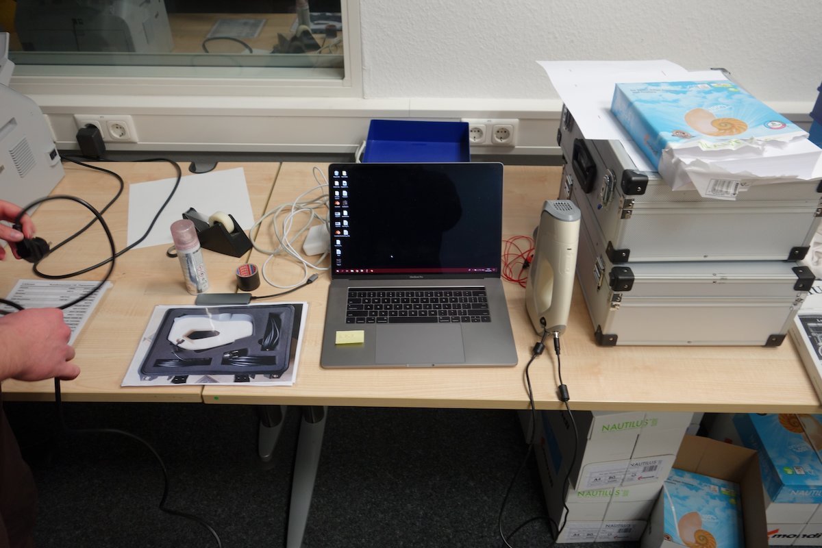
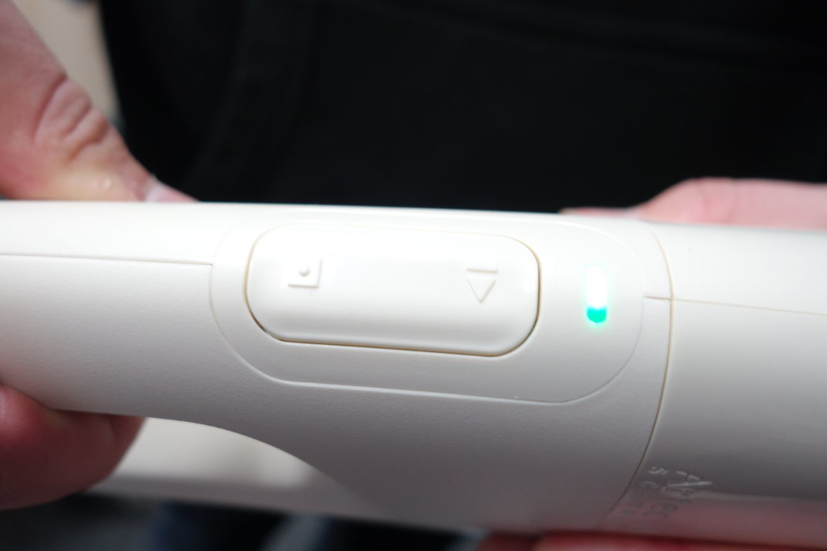
In our lab, we have a 3D scanner from Artec, in particular an Artec Eva. I thought it would be a static machine, suitable to scan small to maybe medium sized objects - I was wrong. The scanner is neither suited to scan small objects, nor is it static. It is hand held and can be moved freely to scan even very large objects. The accompanying software combines the scans, and is able to export textured 3D models as *.obj files.
The scanner uses lasers to sense the distance to the scanned objects. Using already scanned points and a flat reference surface, it is able to derive its own position and orientation relative to the scanned object. Additionally, the scanner features a camera that is used to generate textures for the scanned object. The textures are automatically mapped to the generated 3D model.
When scanning, one has to slowly move the scanner around the target object. The accompanying software shows what the scanner "sees" and whether the distance to the object is ok or not. It also notifies the user if the scanner looses track of the object because one moved to fast or below the reference surface.
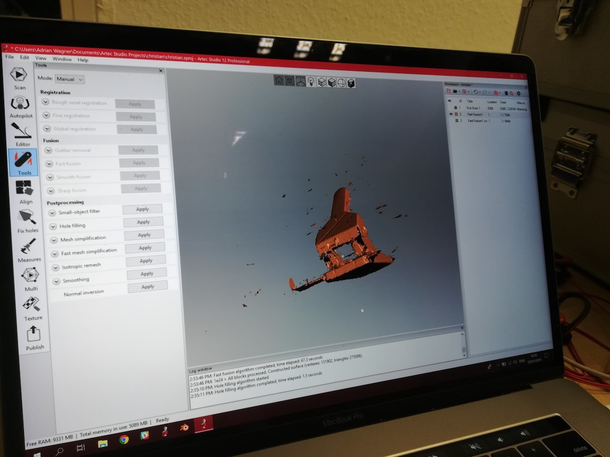
The data from the scanner is sent to Artec Studio, the corresponding software suite running on a laptop connected to the scanner. During the scan, the software displays information on the size of the scan, whether the distance to the object is too large or too small, and what is currently seen by the scanner. After the scan, there are options to optimize the resulting mesh, for example, by removing unnecessary triangles, merging vertices, or adapting the base line of the scan. Finally, the scan can be exported as an *.obj file. For my object, I only ran a mesh simplification.
Printing a nested gyroscope
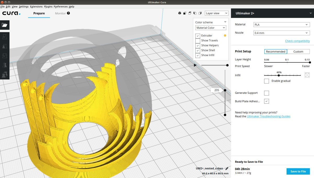
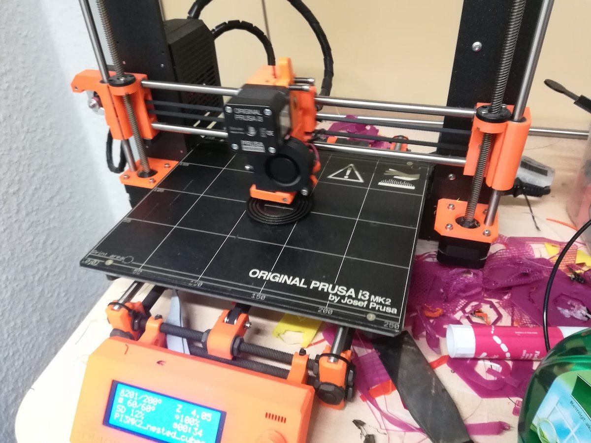
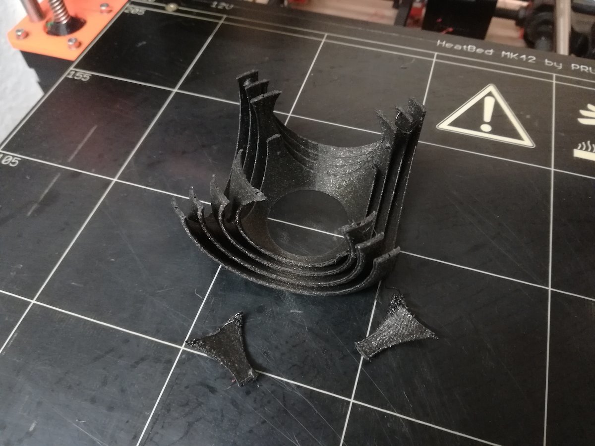
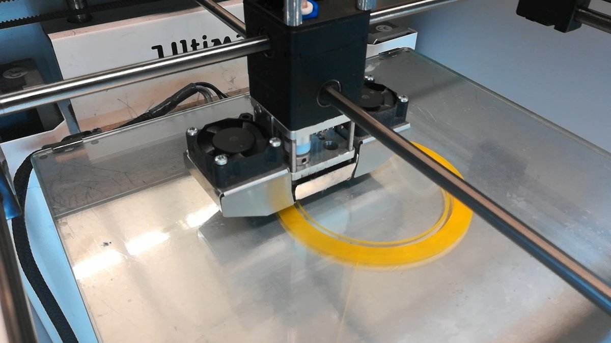
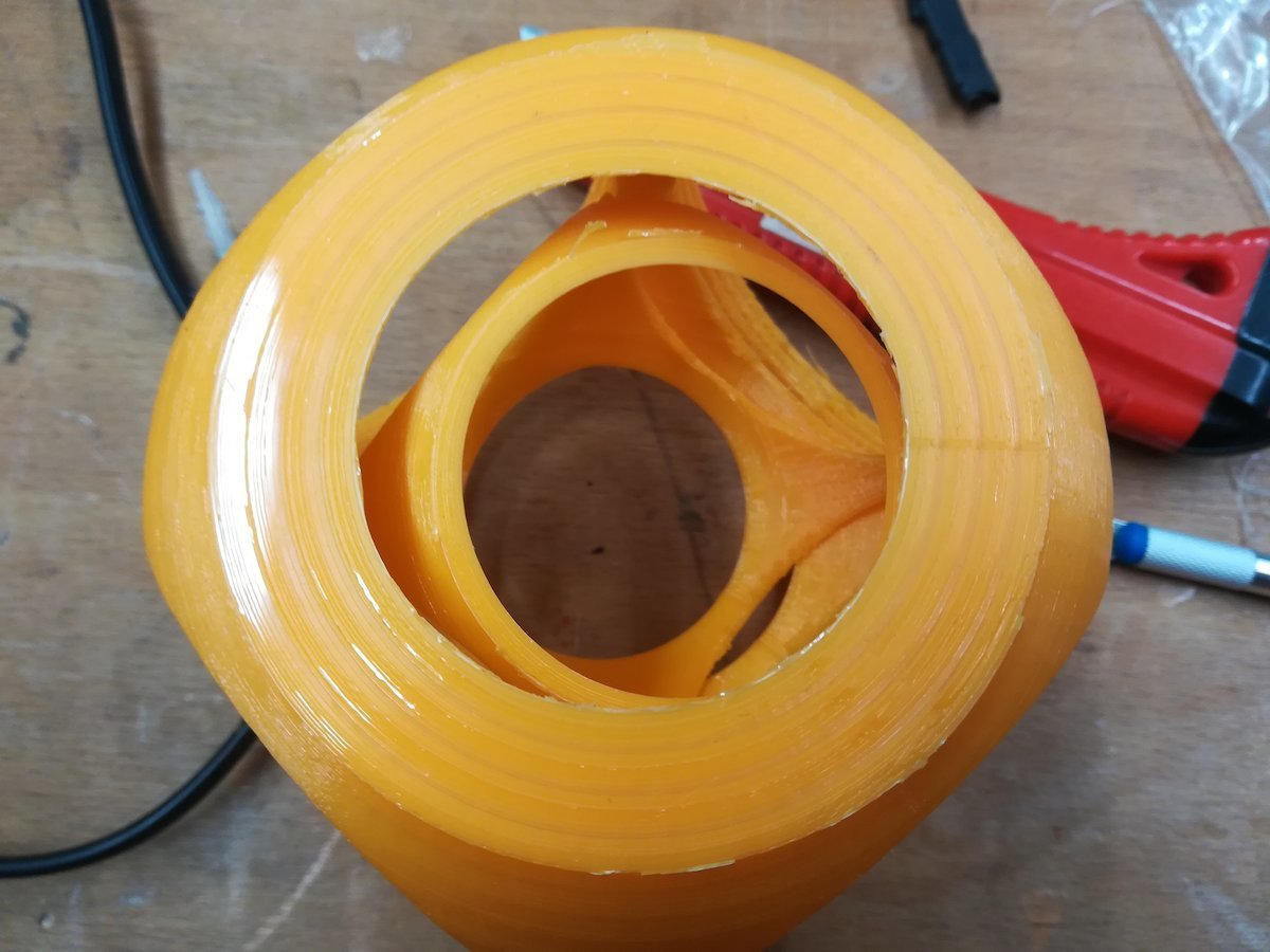
One of our objectives for this week was to use the 3D printer to create something that cannot be made substractively. I wanted to make nested gyroscope similar to this one, but smaller. This cannot be made substractively, because the tool would have to be bent to carve out the round nested structures. So I made my own parametric design with OpenSCAD. From OpenSCAD, I export it as *.stl file. Then, I made use of Cura, an excellent open-source slicing application, to prepare the design for printing. At first, I printed the cubes on a Prusa i3 MK2; however, the print was faulty and did not finish, altough I don't know exactly what problem occured. However, I noticed that part of the joints between the cubes were to small, and could fix the design before the next try. This time, I used an Ultimaker 2+ Extended, and it printed without problems. Apart from the printer itself, the settings stayed the same: 0.1mm layer height, 20% infill, PLA, 0.4mm nozzle. After the print, I had to manually cut the cubes apart, because the printer added a plate at the bottom. But then I finally had my gyroscope!
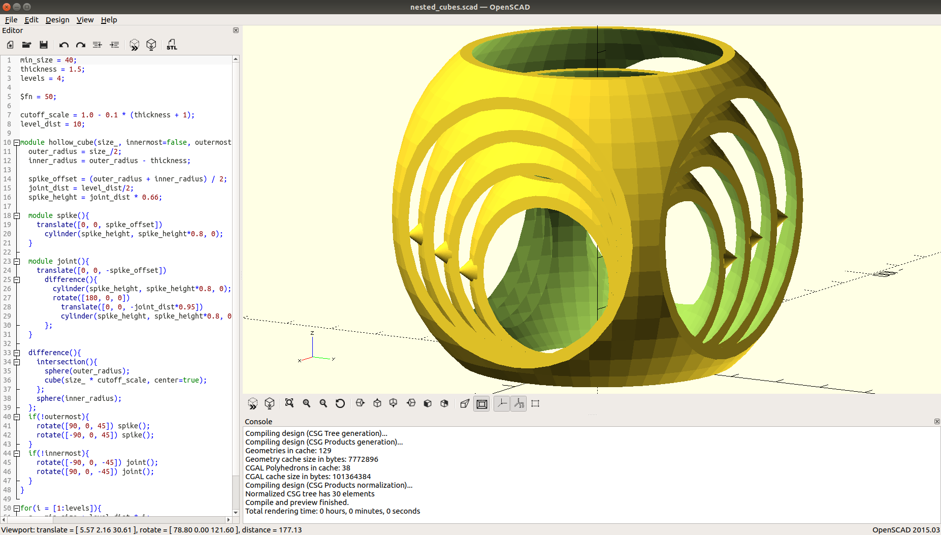
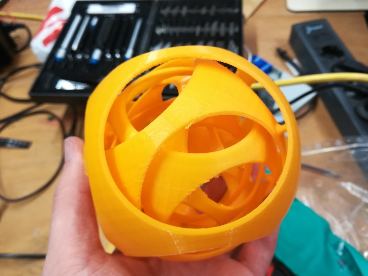
The code defines modules for spikes, joints, and cube parts, which are scaled and nested into each other.
min_size = 40;
thickness = 1.5;
levels = 4;

$fn = 50;

cutoff_scale = 1.0 - 0.1 * (thickness + 1);
level_dist = 10;

module hollow_cube(size_, innermost=false, outermost = false) {
  outer_radius = size_/2;
  inner_radius = outer_radius - thickness;

  spike_offset = (outer_radius + inner_radius) / 2;
  joint_dist = level_dist/2;
  spike_height = joint_dist * 0.66;

  module spike(){
    translate([0, 0, spike_offset])
      cylinder(spike_height, spike_height*0.8, 0);
  }

  module joint(){
    translate([0, 0, -spike_offset])
      difference(){
        cylinder(spike_height, spike_height*0.8, 0);
        rotate([180, 0, 0])
          translate([0, 0, -joint_dist*0.95])
          cylinder(spike_height, spike_height*0.8, 0);
      };
  }

  difference(){
    intersection(){
      sphere(outer_radius);
      cube(size_ * cutoff_scale, center=true);
    };
    sphere(inner_radius);
  };
  if(!outermost){
    rotate([90, 0, 45]) spike();
    rotate([-90, 0, 45]) spike();
  }
  if(!innermost){
    rotate([-90, 0, -45]) joint();
    rotate([90, 0, -45]) joint();
  }
}

for(i = [1:levels]){
  s = min_size + level_dist * i;
  translate([0, 0, s/2 * cutoff_scale])
    hollow_cube(s, i==1, i==levels);
}
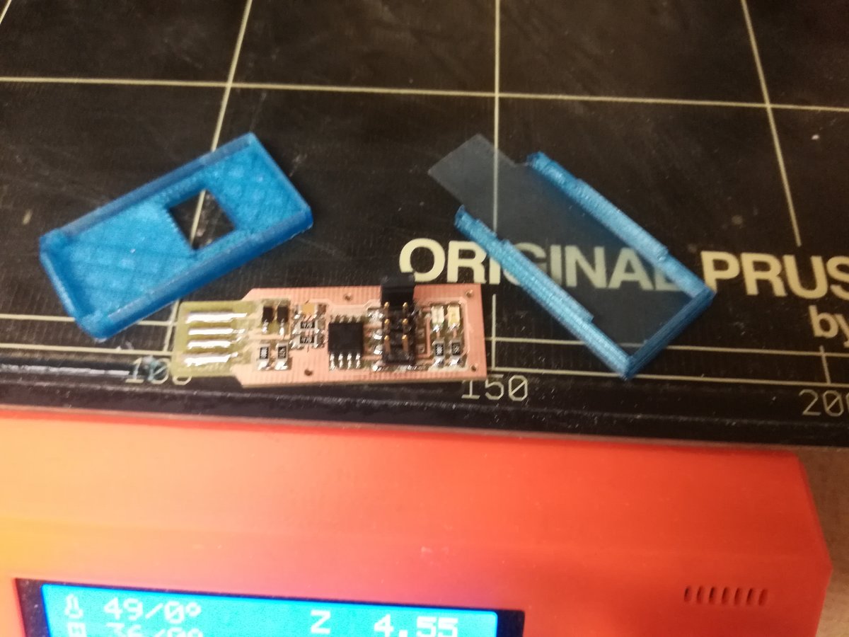
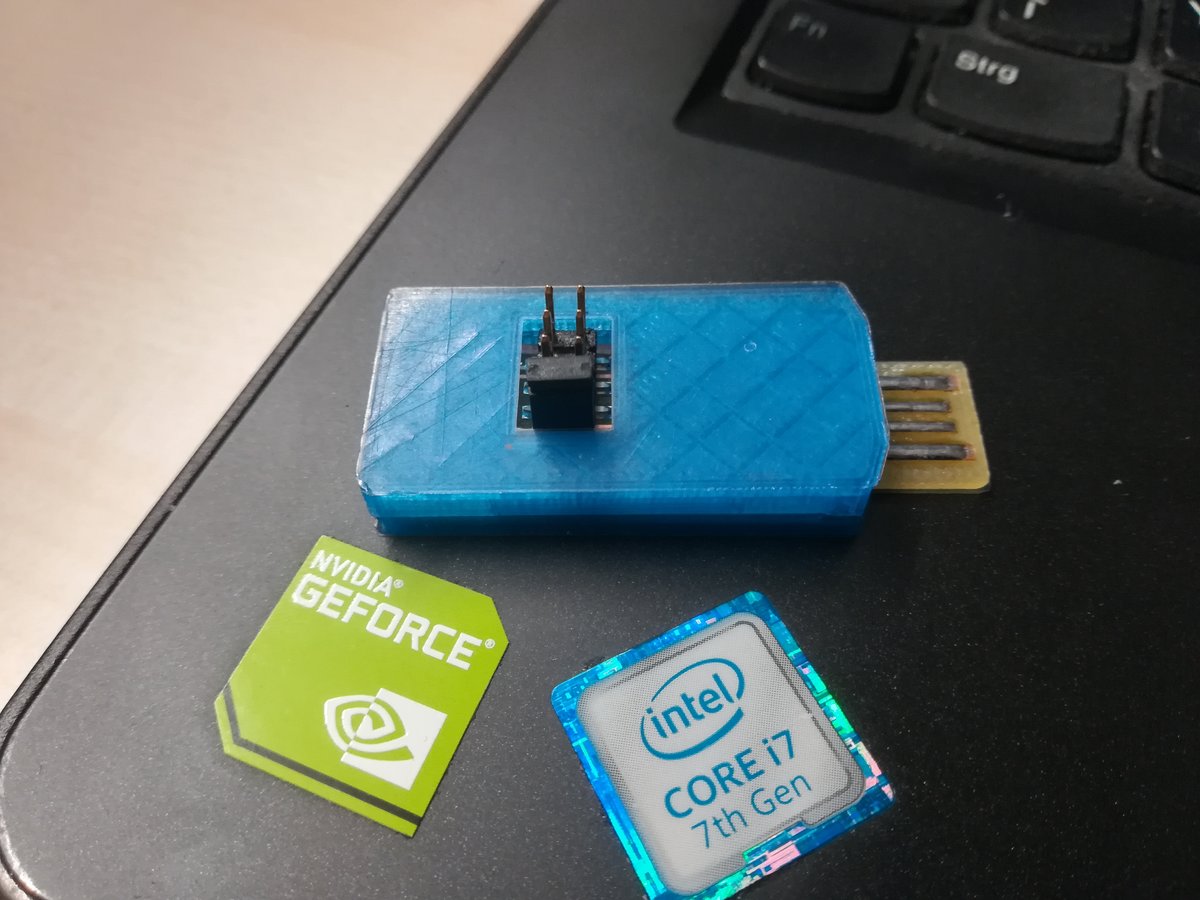
Parametric 3D printed case for the FabTinyISP
I designed a case for my ISP in FreeCAD. I wanted this design to be fairly general, so you can change a couple of parameters like the dimensions of your board, desired thickness of walls, or the size of openings. It took me a couple of iterations to get it right - mainly because I wanted it as small as possible, and made the walls too thin -, but now my board fits very well. I printed it on a Prusa i3 MK2.
The case consists of an upper part and a bottom part, which were created with the "part design workbench". FreeCad has lots of different workbenches, each containing a somehow coherent collection of tools, for different purposes. Most often I used the part workbench (provides geometric primitives and boolean operations between objects), part design workbench (design a nontrivial part by extruding sketches, making pockets, holes, etc.), and the sketching workbench (construct 2D sketches with geometric constraints).
Parametric design in FreeCad is conceptually easy, but the interface is not quite user friendly (or at least I didn't find an easier way).
In the versions I used (versions 0.17 and 0.18), one is able to reference each parameter (e.g. sizes, position, orientation, constraints, part names) of an object (e.g. sketches, parts) by name using a hierarchical naming pattern.
These references can be used to calculate values for other parameters.
For example, using the part design workbench, one might have a part named Cube
made from a pad named Base extruded from a sketch called Base_Sketch with a constraint DimA.
Then, the value of the constraint can be referenced as Cube.Base.Base_Sketch.DimA.
Unfortunately, the text fields for formulas are always a single line high and quite short.
Also, typing these names gets tedious very fast.
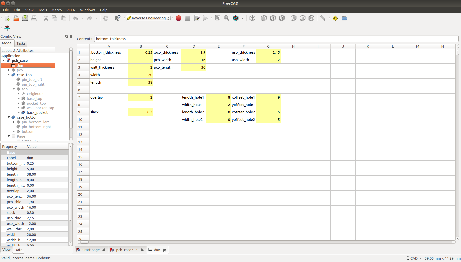
When using more than a couple references that are used in a lot of places, it is easier to create a spreadsheet (in the spreadsheet workbench), and attach names to cells.
Another advantage is that all relevant parameters are bundled in one place.

Conclusions
I had never worked with 3D printers before this assignment, but I knew about the possibilities of the process, so I was pretty excited about finally testing it for myself. I was not disappointed, 3D printing definitely is as cool as everyone says it is. During this week, and even more during the rest of the Fab Academy, I learned how to design objects that can be printed with high reliability (avoid steep angles, for example) and how to troubleshoot failed prints.