Assignment 09 Embedded Programming
In this weeks Assignment we had to program the Hello-World-Board we made in the Electronics Design Assignment,
furthermore we had to read the the datasheet of of the mircocontroller.
We also had to do a group-assignment about the performance and development workflows for other architectures. The results can be found here. I already worked a few times with a raspberry pi but I never got the hang of it for the most tasks I used other smaller microcontrollers like the ATTiny and the ATMega. For this assignment I used did not use the Fab ISP since I wanted to test if the I can program the ATTiny with the Arduino IDE this will come in handy for more complex programs because native C-code can be very hard to read.
We also had to do a group-assignment about the performance and development workflows for other architectures. The results can be found here. I already worked a few times with a raspberry pi but I never got the hang of it for the most tasks I used other smaller microcontrollers like the ATTiny and the ATMega. For this assignment I used did not use the Fab ISP since I wanted to test if the I can program the ATTiny with the Arduino IDE this will come in handy for more complex programs because native C-code can be very hard to read.
Tools used
- Arduino Uno
- Jumper Wires
Read the Datasheet
First we had to read the datasheet of the microcontroller we used. In my case I used the ATtiny44. I already used and read datasheets of several microcontrollers, usually I go to Sparkfun to get datasheets for all electronic parts I use. This time I could not find the proper datasheet there, but I found the datasheet here on the website of the FabCentral. The used this sheet the first time while soldering the Hello-World-Board to check how the microcontroller has to be orientated.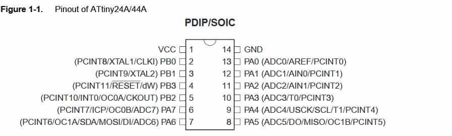
You also can derive the the pin layout from the schematic, this is especially important when designing a board
with analog inputs and outputs: You can use an analog pin like a digital pin but not the other way around.
A digital input/output pin has only two modes 0V and 5V an analog pin can provide and sense values between 0V and 5V.
Furthermore you can get advanced information about the chip like how many registers it has or how commands are exactly executed.
For example you can implement your own memory allocation algorithms by directly accessing the registers or even write a whole operating on a microchip.
Furthermore you can get advanced information about the chip like how many registers it has or how commands are exactly executed.
For example you can implement your own memory allocation algorithms by directly accessing the registers or even write a whole operating on a microchip.
Programming the Board
Since I wrote a whole operating system for a microcontroller in plain C for a practical course at my university, I do not really use it for simple tasks. If you want to mess with the hardware on a very low level for example allocate memory manually, plain C is a little bit overkill. C provides many features but is very unforgiving when you make mistakes. Furthermore when you are used to high level programming languages it is sometimes hard to read. For the most tasks the Arduino IDE is my way to go. It provides and easy to understand IDE and the code produced is readable.For beginners it is also easy to learn because it is very well documented and for almost every sensor or external tool there is a library which you can easily integrate into your programs. A good example for this ist the library for the Adafruit Neopixel this library can be used to control WS2812 LEDS (basically programmable multicolor Led-Stripes).
To program the Hello-World-Board I used the Arduino IDE and an Arduino Uno. To use Arduino Uno as an ISP I used this tutorial and this extension to get the ATtiny to work properly.
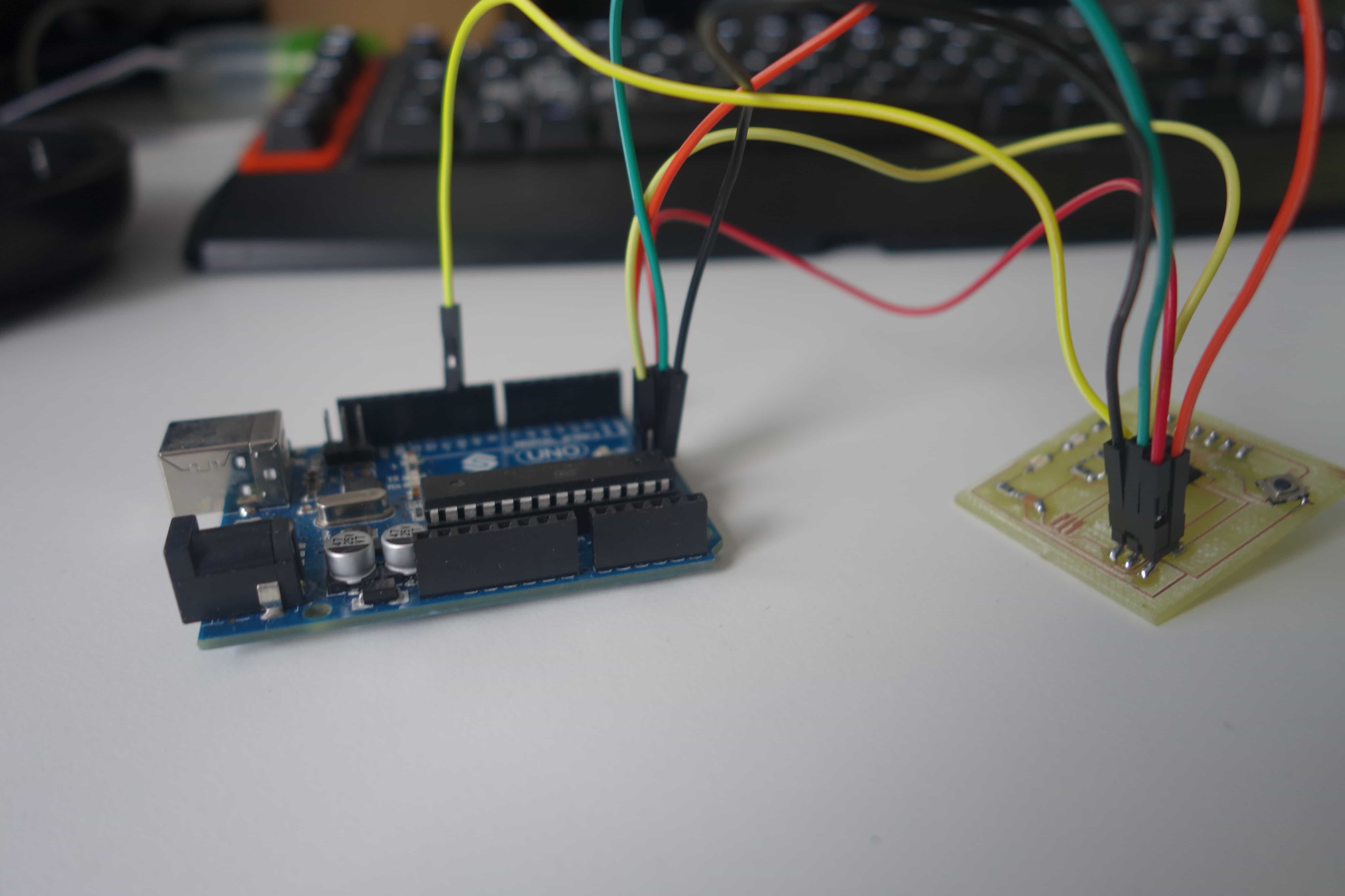
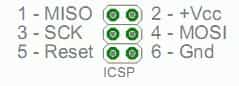
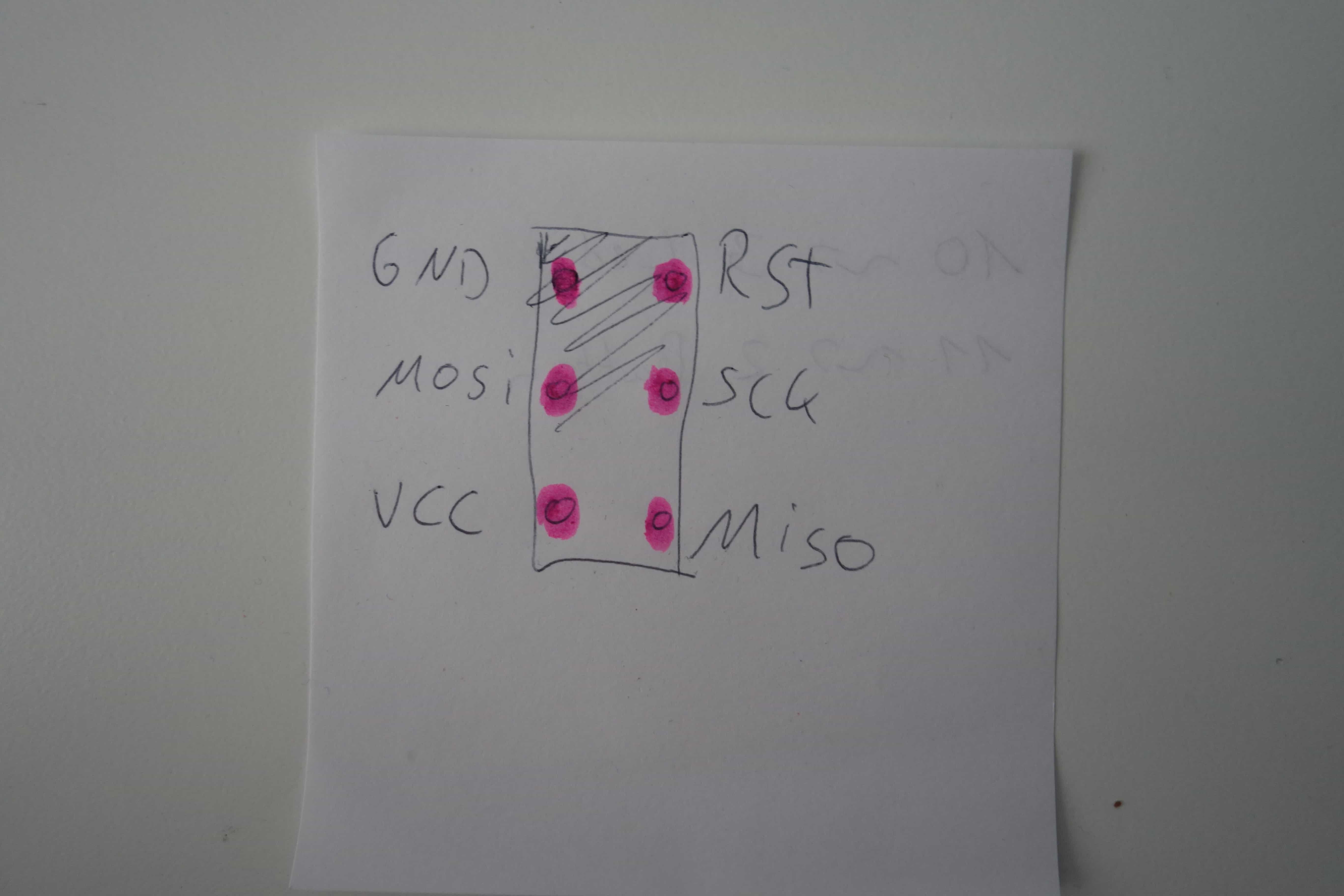
Start by connecting the Arduino to the Hello-World-Board. I had to look up the pins for my board
in the board layout files. Note that you should connect the RESET-pin of the Hello-World-Board
to the D10-pin of the Arduino.
Arduino-pins
Board-pins
Now upload the ISP program to the Arduino you can find it under File->Examples->ArduinoISP->ArduinoISP. Then press the upload button.
To install the extension goto File->Preferences. Under "Additional Boards Manager URLs" paste this link :
"https://raw.githubusercontent.com/damellis/attiny/ide-1.6.x-boards-manager/package_damellis_attiny_index.json"
and hit OK.(If you have multiple URLs separate them with a comma)
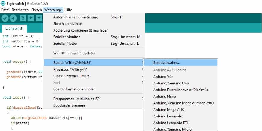
To burn the bootloader onto the ATtiny go to Tools->Board->Boards Manager. Search there for the ATtiny and install it. You now can select it under Tools->Board. Now go to Tools->Processor and select ATtiny44.
Finally Hit Burn Bootloader under Tools. Make sure that you use the same port the Arduino Uno uses.
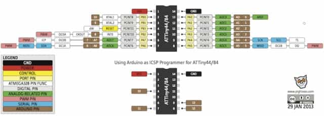
Now you can finally program the board. Since the Pins of the Arduino and the ATtiny are a little bit different
use the graphic above to find the pins you have to use. In my case it was Pin3 for the Led-Output and Pin2 for the Button-Input.
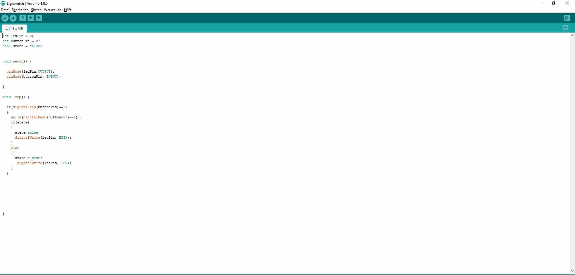
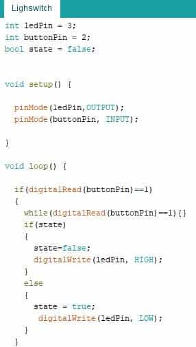
I wrote a simple program so the switch will operate like normal lightswitch:
First you have to define the two pins as input and output via the pinMode command.
Then the program loop starts if the button ist pressed i.e. the digitalRead of the button is 1 the program will enter a loop as long as the button is pressed. When the button is released the mode of the led is changed via the digitalWrite command depending on the state variable.
I also wrote a program that lets the led blink a different speeds you can find both programs as downloads below.
Lighswitch
Blinking LED
Favourite beverage of the Assignment

It's dangerous to go alone drink this.