5. Electronics production
Assignments for this week
- Group Assignment
To characterize the design rules for the PCB production process. - Individual Assignment
Make an in-circuit programmer by milling the PCB
Let’s Start
I had fabricated a few PCBs in my college using etching process but this time we had to do it using the milling machine.
In our lab, we have monoFab SRM-20 for milling PCBs.
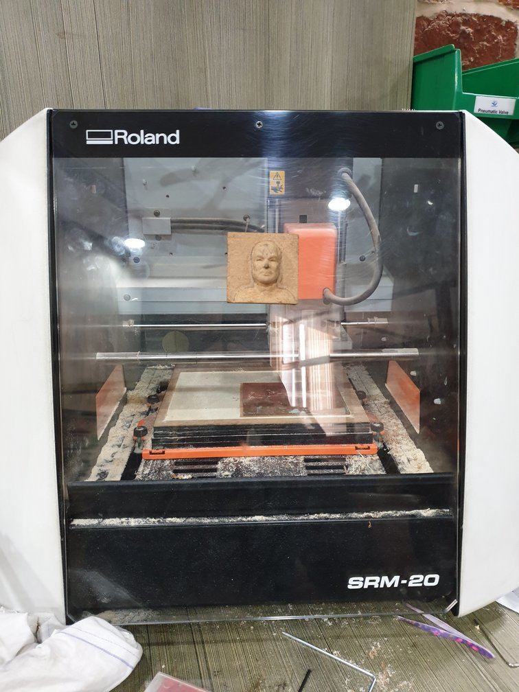
I always read the user manual before operating any machine for the first time, which is a good habit, so I started with going through the user manual of the machine.
In this, I read about basic operations of the machine, different cutting tool types, cutting material types etc.
I also get to know that the maximum cutting area of this machine is 203.2mmX152.4mm. The maximum depth it can cut is up to 71mm.
Software
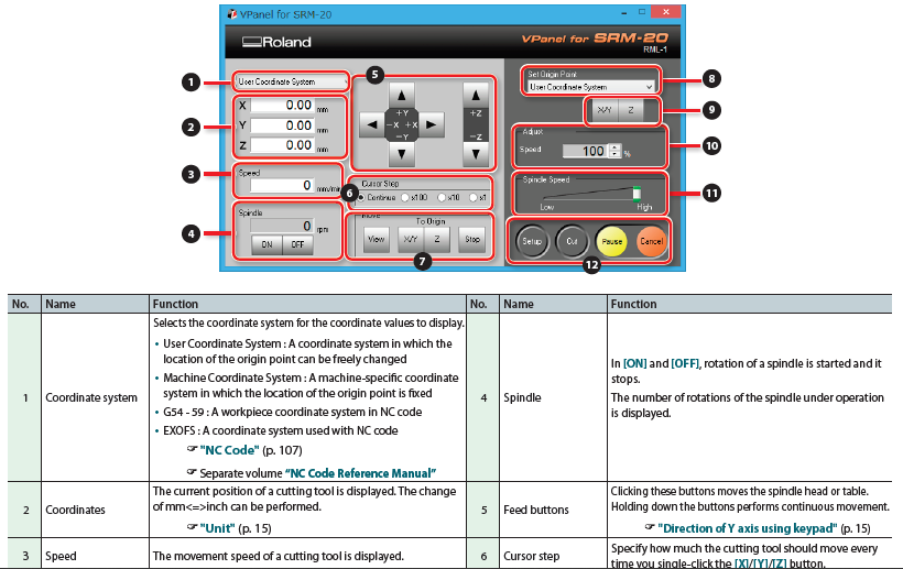
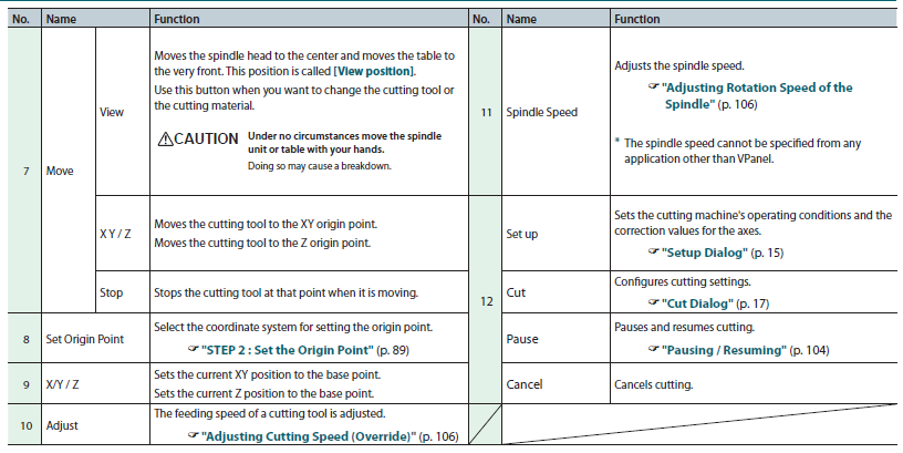
“VPanel for SRM-20” is the software for controlling this machine. It can be downloaded from here
- User Interface of VPanel
Test File
- I downloaded the test file from the FabAcademy schedule page.

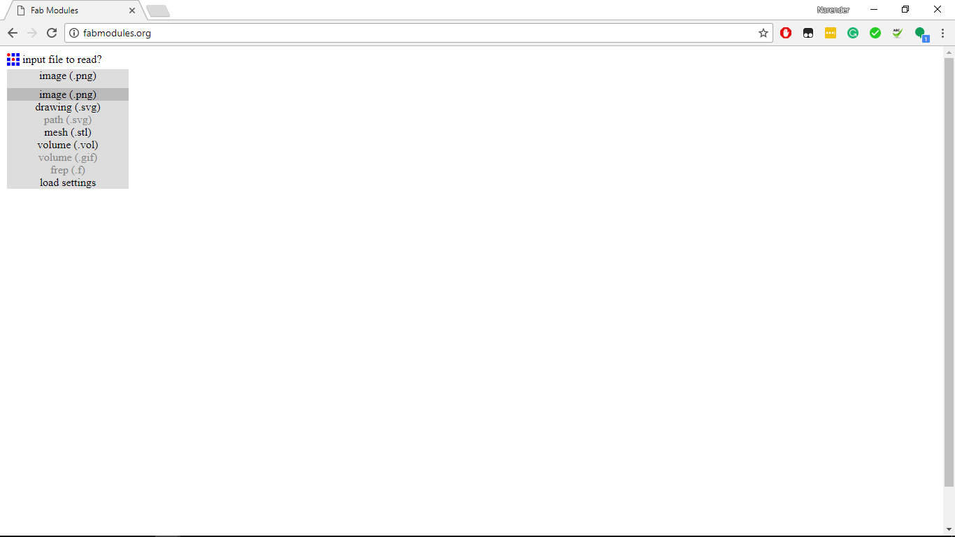
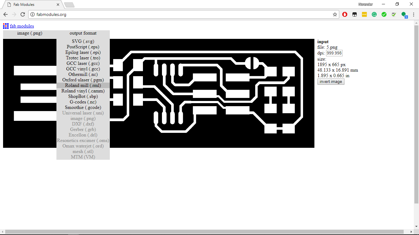
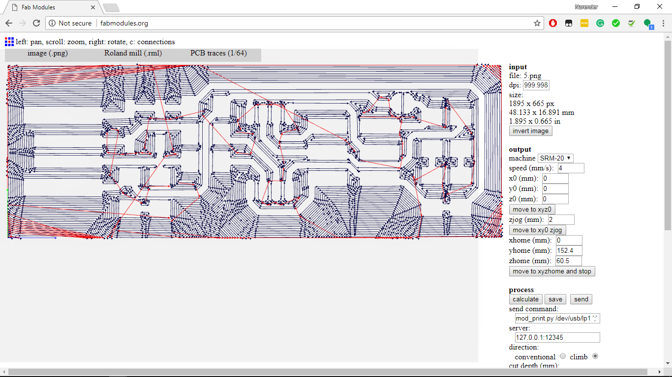
- Then used fabmodules to feed settings for cutting and generating the .rml file.
- Finally, imported the rml file in the VPanel and milled the PCB.
Output
Issues
We faced some issues while milling the FabISP. Our traces were not coming properly. We figured out that our bed was leveled. Also at some places, the tool was reaching at its max depth.
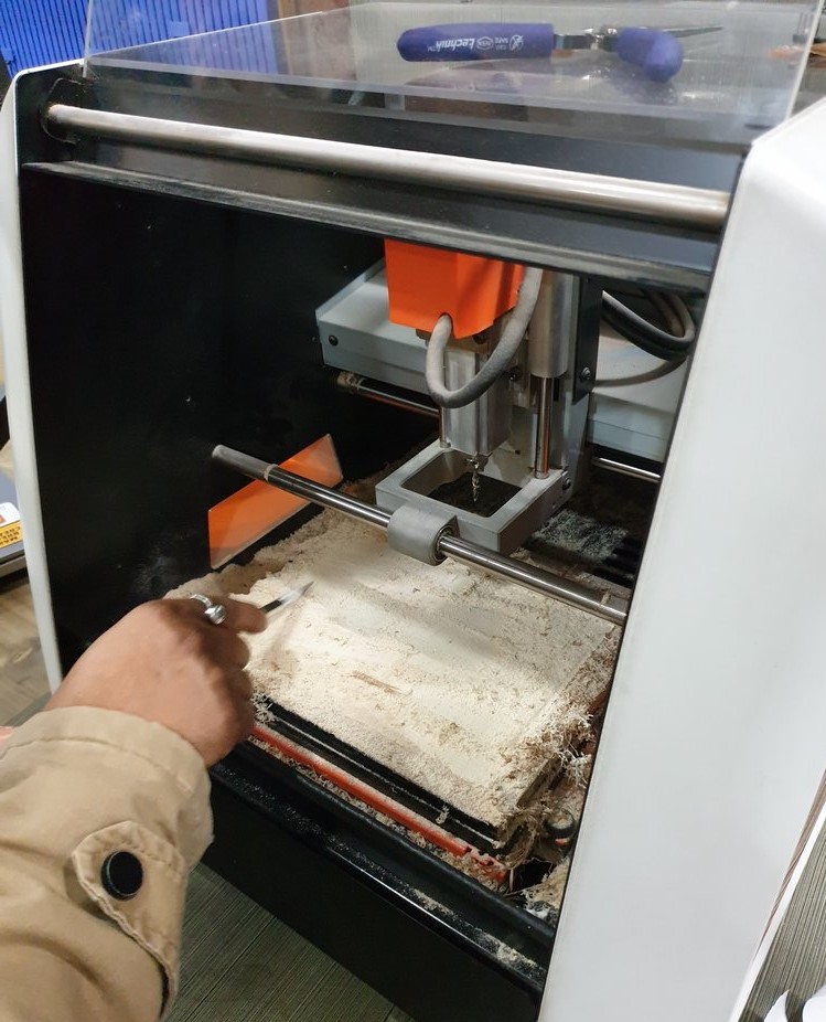
Issue resolution
- we created a new sacrificial layer.
- Then did surfacing which took almost 2 hours.
Steps for surfacing
- We chose an acryilc sheet as the new base layer.
- using laser cutter we cut the acrylic piece of 230X150mm
- After that using DST, paste the acrylic sheet onto the bed of the machine.
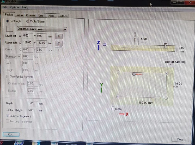
- For surfacing we used the software ClickMill.
- In the software, select a rectangular pocket of 180X140mm with the cutting depth of 1mm.
- Press cut to start milling.
- Then just simply wait for 2-2.5 hours :P
FabISP
- Next task was to make the FabISP.
What is FabISP
The FabISP is an in-system programmer for AVR microcontrollers, designed for production within a FabLab. It allows you to program the microcontrollers on other boards you make.
- I started with downloading the png file of the board
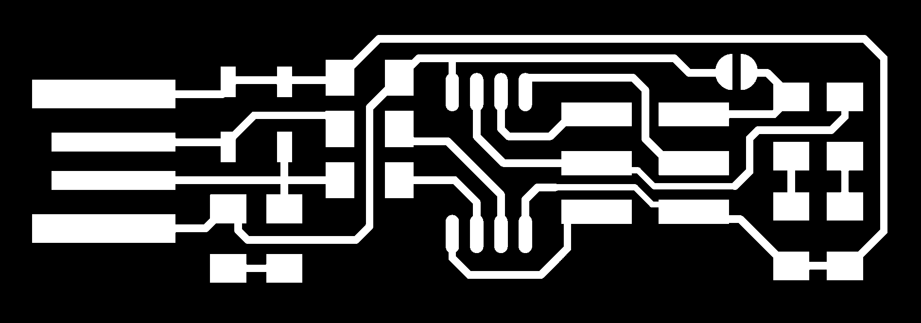
- Then opened and processed the image in fabmodules
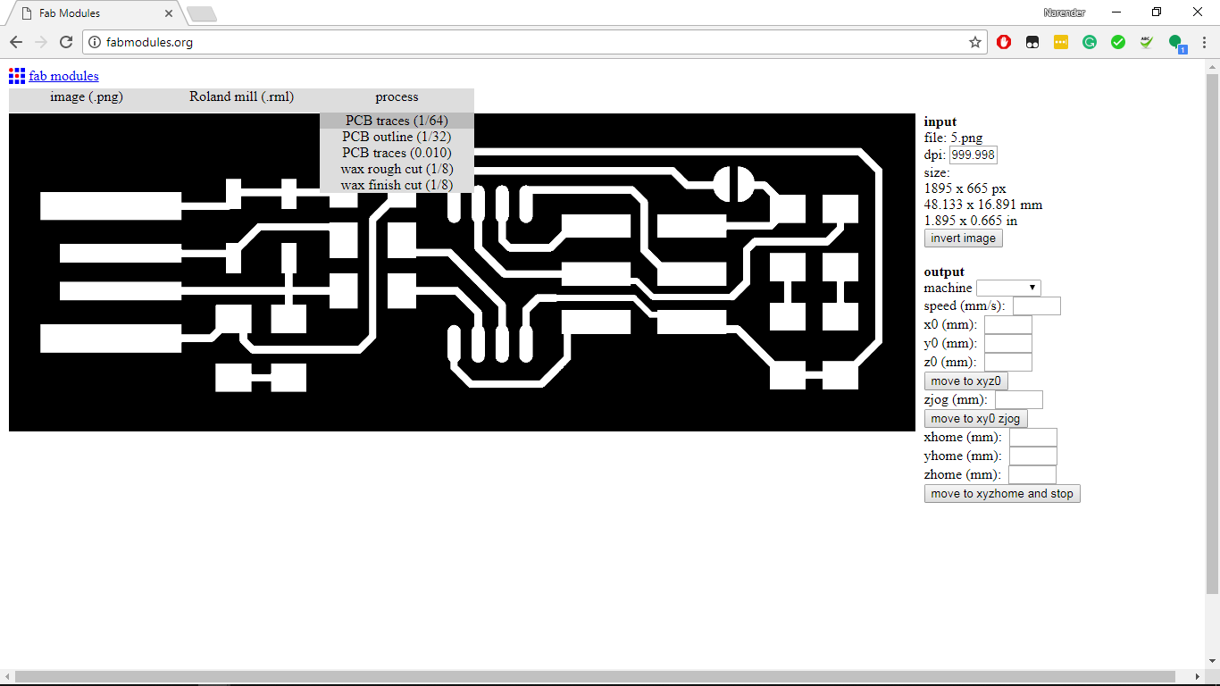

- Click on calculate and save the file.
- Next, I opened the fts_mini_cut for cutting the outlines.
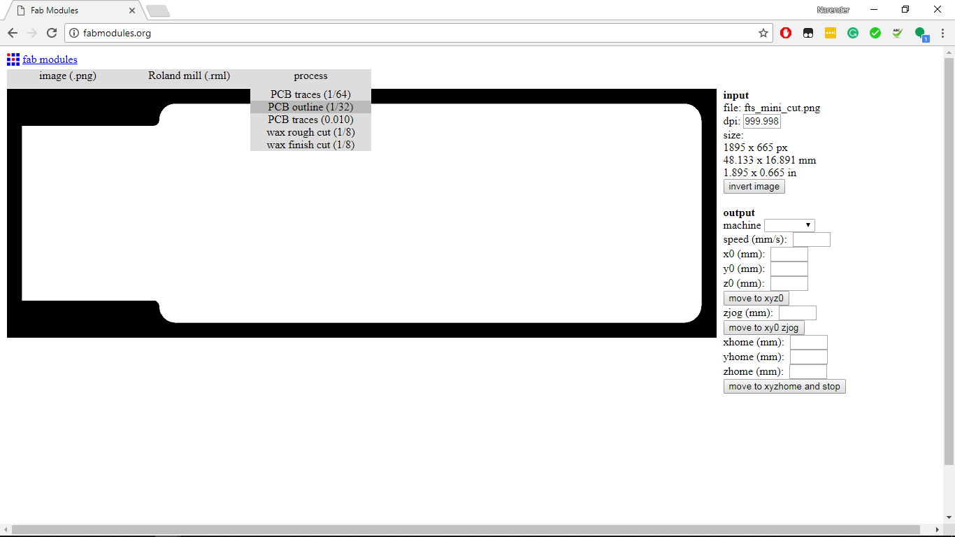

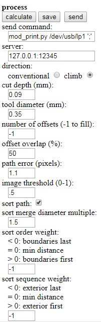
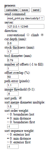
- Settings I used for cutting outlines
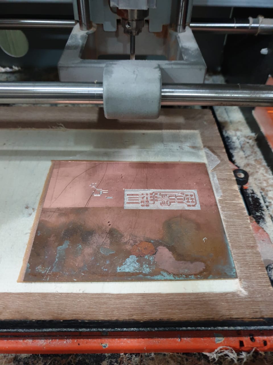
- Next, I opened VPanel for milling the prepared files.
- Here, click on “cut” to select the downloaded rml file and then click on “output” to start milling.
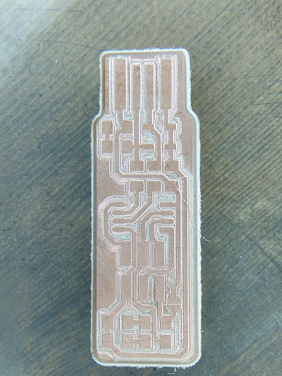
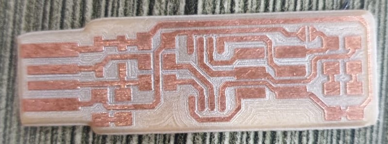
- Milled PCB
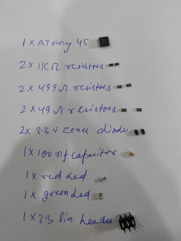
Required electronics components to build the board
- 1x ATtiny45 or ATtiny85
- 2x 1kΩ resistors
- 2x 499Ω resistors
- 2x 49Ω resistors
- 2x 3.3v zener diodes
- 1x red LED
- 1x green LED
- 1x 100nF capacitor
- 1x 2x3 pin header
.jpeg)
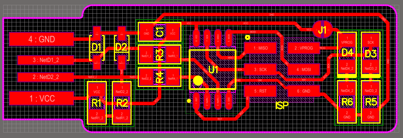
Schematic
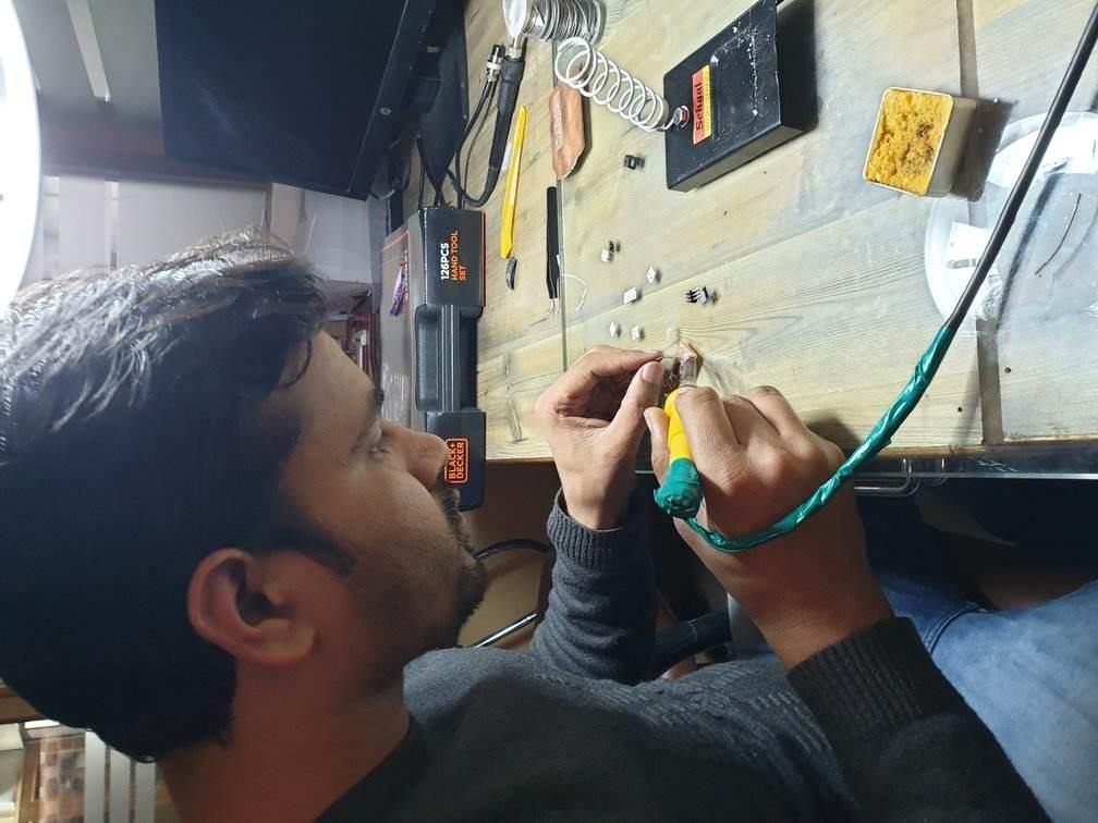
Soldering time
- For soldering, we used Soldron station. I set the temperature of soldering iron around 330C. The key to solder SMD components is first tin the pads using soldering wire and then place components on the pads. Next, heat the pad and component terminal and apply a little bit of solder, keep the components pressed using tweezer while soldering.
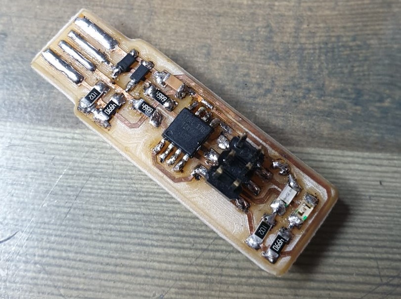
Final Board
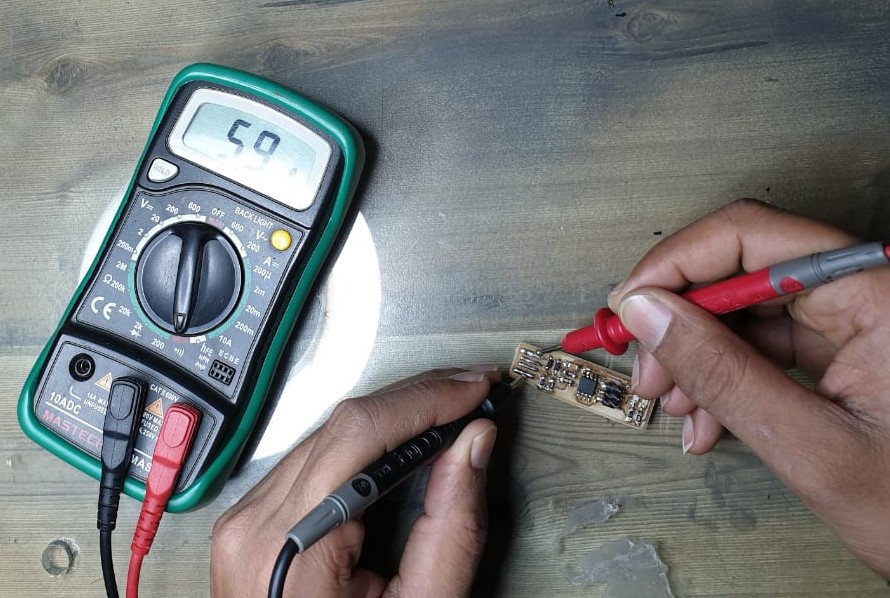
Continuity Test
- In the continuity test, I checked for the shorting between various pins and paths.
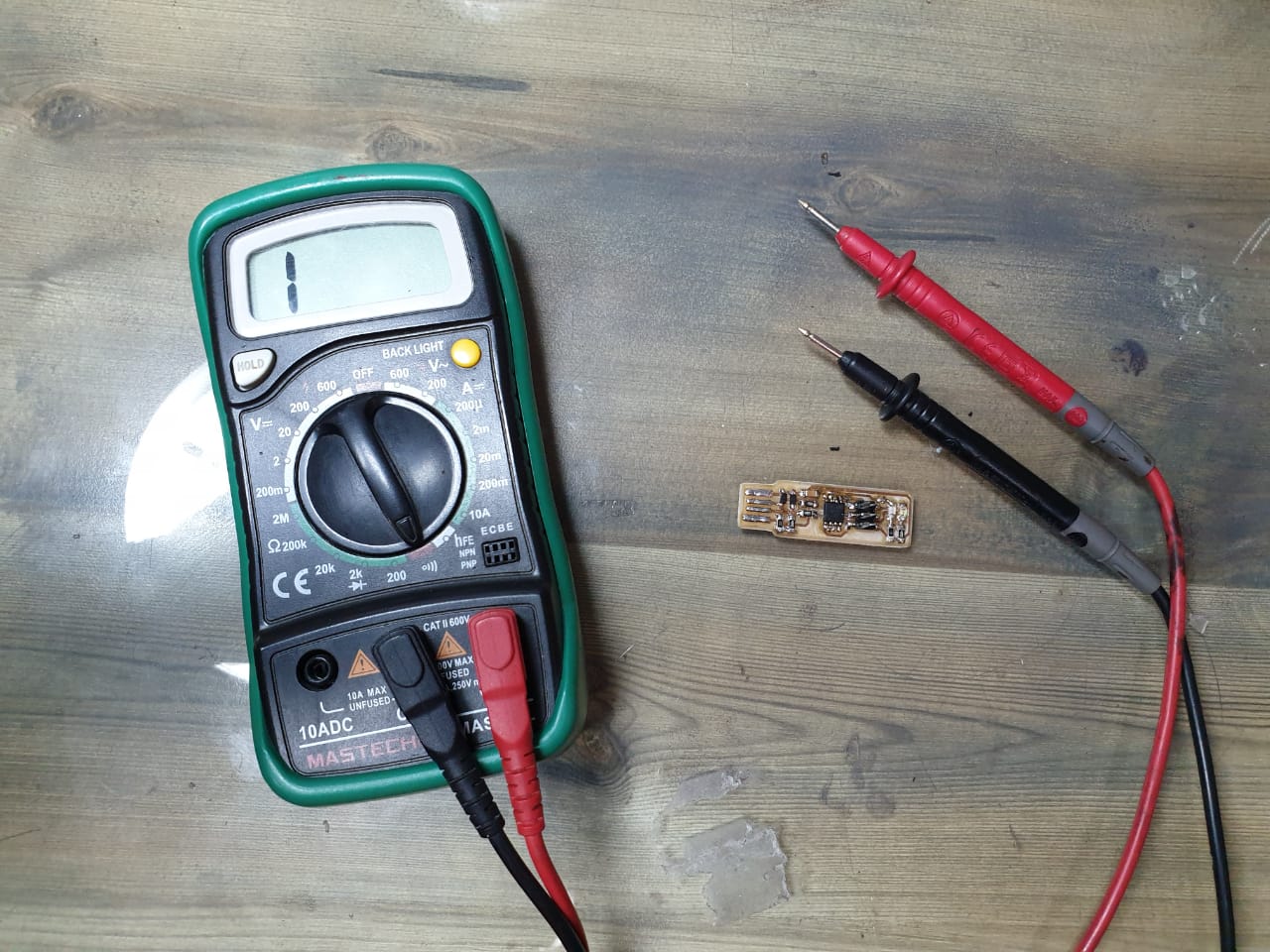
- If the paths are continuous or short, the multimeter buzzes a sound and displays 1 on the display.
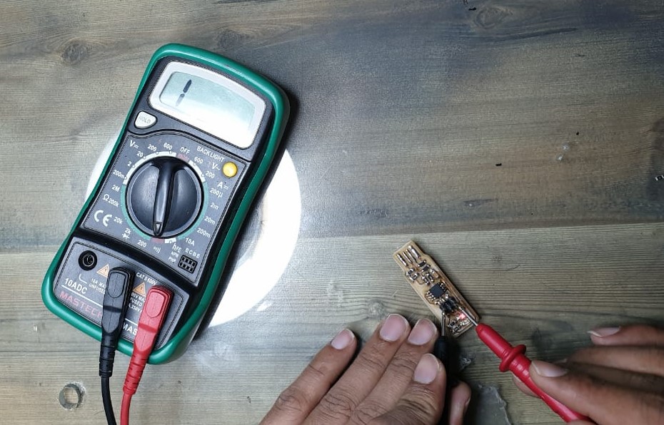
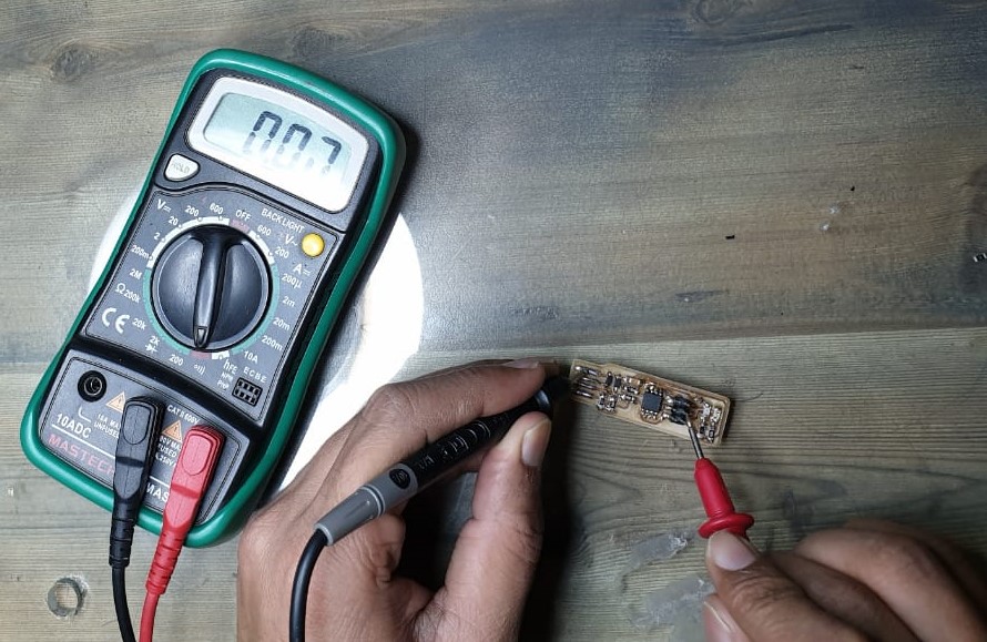
- If the paths are not continuous or the pins are not short, no sound comes and displays shows value other than 1.
Programming FabISP
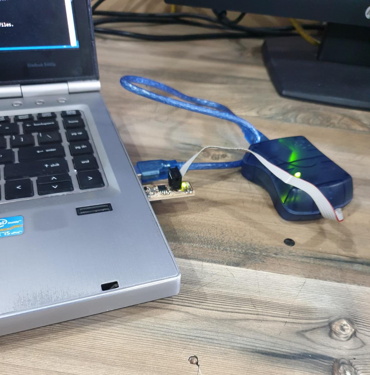
Connections
Connect the AVRIsp and the fabisp using jumper wires or 2X3 ribbon cable. There is a dot on the connector of the ribbon cable which signifies the MISO pin. connect that pin to the miso pin on the fabisp.
Then, connect the fabisp into the usb jack of the laptop.
For programming the FabISP I followed the instructions given on Brian’s page.
Steps
- First, download the Atmel AVR toolchain and extract the files in c:\program files.
- Download GNU Make and install in c:\program files(86) directory.
- Install avrdude.
- Then, update the path to tell the windows where to locate the tools you’ve just installed. Follow instructions on Brian’s page.
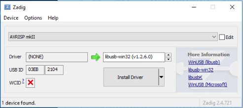
- Download Zadig to install the drivers.
- Connect the FabISP, select AVRISP mkII as the programmer and install libusb-win32 driver.
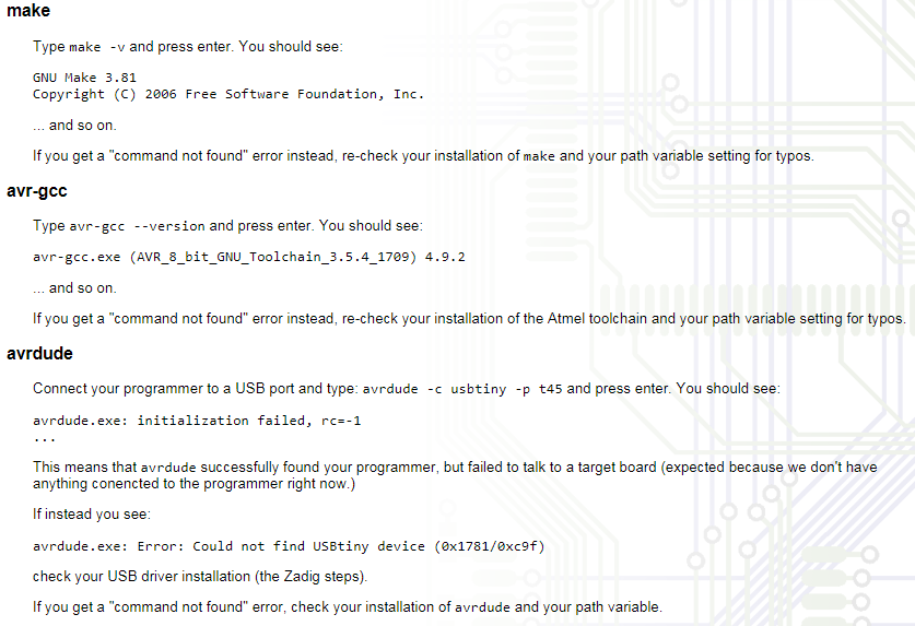
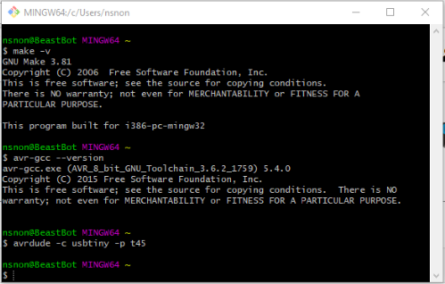
- Do sanity check using the below commands.
- Next step is to download the firmware file. Unzip and extract the files.
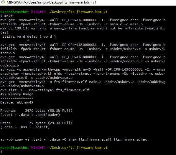
- Open your terminal program and navigate to the directory(firmware) and run make command. It will generate a hex file (firmware_fts.hex).
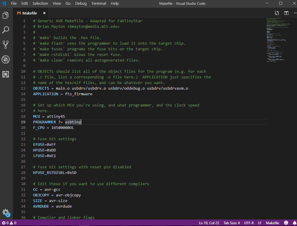
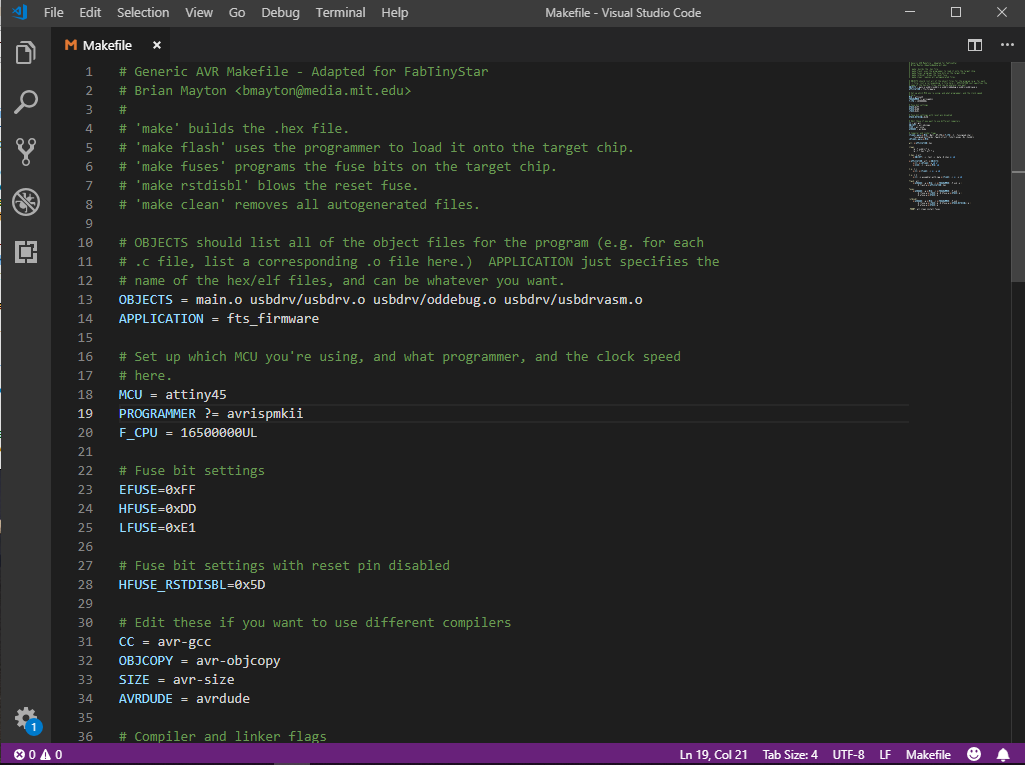
- Open the hex file and change the name of the programmer from usbtiny to avrispmkii
- Connect the board to the USB jack and programmer to the ISP header of the board. Make sure the orientation is right(MISO –> MISO).
- Run make flash. This will erase the target chip, and program its flash memory with the contents of the .hex file you built before.
- Run the make fuses command. This will set up all of the fuses except the one that disables the reset pin.
- Run make rstdisbl. This does the same thing as the make fuses command, but this time it’s going to include that reset disable bit as well.
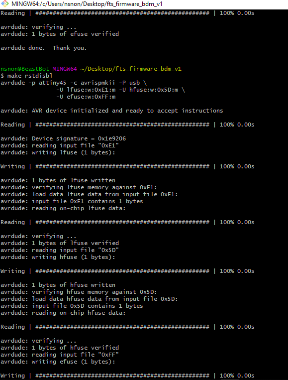
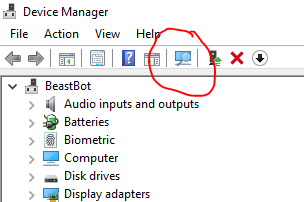
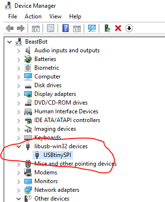
- Then, check that if the fabIsp is being detected in your windows or not. For that, connect the fabISP to your usbport and open device manager. Scan for hardware changes and look for “libusb-win32 devices”, under this you will see “USBtinySPI”. If it’s there, congrats, your programmer is ready to program other microcontrollers.
Learning outcomes
- I successfully milled the PCB using monoFab milling.
- Got to know about FabISP.
- Successfully programmed the FabISP to make it program other boards.

This work is licensed under a Creative Commons Attribution-NonCommercial-ShareAlike 4.0 International License.