6. 3D Scanning and printing
Assignments for this week
- Group Assignment
To test the design rules of the 3D printer. - Individual Assignment
design and 3D print an object (small, few cm3, limited by printer time) that could not be made subtractively 3D scan an object
Types of manufacturing processes.
-
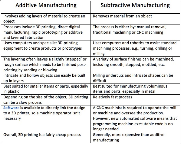
Additive manufacturing- Additive Manufacturing is a process by which 3D objects are constructed by successively depositing material in layers such that it becomes a predesigned shape.
-
Subtractive manufacturing- Subtractive manufacturing is a process by which 3D objects are constructed by successively cutting material away from a solid block of material. Subtractive manufacturing can be done by manually cutting the material but is most typically done with a CNC Machine.
Additive vs Subtractive manufacturing
3D Printing
3D printing is any of various processes in which material is joined or solidified under computer control to create a three-dimensional object, with the material being added together (such as liquid molecules or powder grains being fused together), typically layer by layer.
The term “3D printing” originally referred to a process that deposits a binder material onto a powder bed with inkjet printer heads layer by layer. More recently, the term is being used in popular vernacular to encompass a wider variety of additive manufacturing techniques.
Types of 3D printing
- Fused Deposition Modeling (FDM)
- Stereolithography (SLA)
- Digital Light Processing (DLP)
- Selective Laser Sintering (SLS)
- Selective Laser Melting (SLM)
- Electronic Beam Melting (EBM)
- Laminated Object Manufacturing (LOM)
- Binder Jetting (BJ)
- Material Jetting (MJ)
Fused Deposition Modelling
FDM is a 3D printing process developed by Scott Crump and then implemented by Stratasys Ltd., in the 1980s. It uses production-grade thermal plastic materials to print its 3D objects. It’s popular for producing functional prototypes, concept models, and manufacturing aids. It’s a technology that can create accurate details and boasts an exceptional strength to weight ratio.
Process
- Before an object can be printed, its CAD file must be converted to a format that a 3D printer can understand — usually .STL format.
- Then the user has to slice the 3D CAD data (the 3D model) into multiple layers using special software called slicer.
- The sliced CAD data goes to the printer which then builds the object layer at a time on the build platform by extruding the material, which is usually in the form of filaments, from a heated nozzle.
Here you can learn more about other 3d printing processes.
Design rules
We have Makerbot replicator z18 3D printer in our lab.
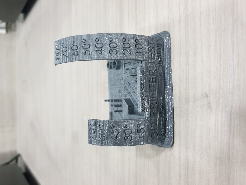
Torture test
A torture test is a hardware assessment of a machine where the device is run at or near full capacity for an extended length of time. The results of the torture test are studied and used to ensure the reliability of the machine under normal conditions.
A torture test may also be referred to as a stress test.
I printed this file to test the capabilities of our 3d printer
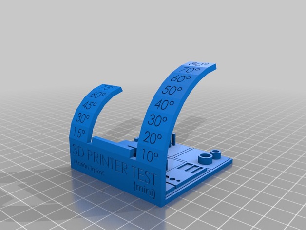
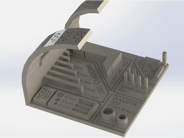
This test includes
- Overhang test
- bridging test
- Stringing test
- Sharp corner test
- tolerance test
- scale test(diameter test)
Overhang test
Think of the letters Y, H, and T. The letter arms of the letter Y consist of two overhangs at a 45° angle. The crossbar of the letter T consists of two overhangs at a 90° angle. The letter H, on the other hand, contains no overhangs at all but does include a bridge which is supported at either end by two uprights.
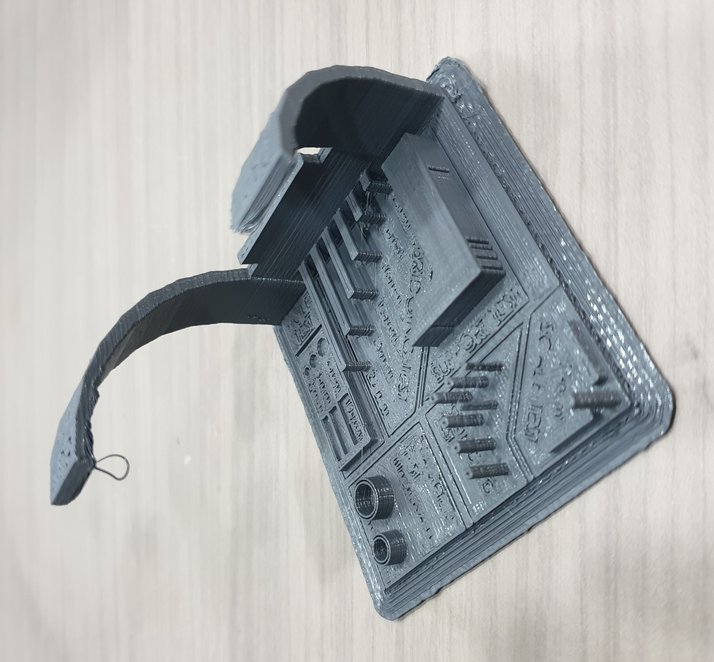
- Our result
The Printer printed overhangs up to 50 degrees. Above 50 degrees print has an overhang.
Bridging test
Bridging is the printer’s ability to print a layer between gaps in lower layers without support, essentially printing over thin air, creating a “bridge”. It is very important that the printer can properly bridge because many prints require some bridging.
- Our Result
In this test, our printer printed bridges up to 20 mm without any issue.
Stringing test
Stringing, also often referred to as Oozing, is when a print has small hairs or in extreme cases thick lines of the filament in between the outside perimeter of two print locations.
The two major factors affecting stringing are Retraction and Temperature.
Retraction causes your printer to pull some filament back when moving the print head in between parts of your print.
Too high of a temperature can make your filament really thin meaning it can come out the extruder tip just from a little gravity. This is pretty easily fixed by dropping your extruder temperature by 5ish degrees C
- Our Result
There was some oozing issue while printing pillars. It can be minimized by increasing retraction distance.
Sharp corner test
This is the ability of a printer to print sharp corners smoothly and easily.
The rounded corners are caused by a combination of two things. minor overextrusion at the corner, as the print head slows but there is still pressure on the filament from printing quickly..... And heat builds up at the corner due to the nozzle slowing down, combined with the elasticity of the hot plastic seeking the shorter round path rather than a tight corner.
Unfortunately, these two actors conspire to round all “sharp” corners on FDM machines to some degree
Tolerance test
In 3D printing, like any other manufacturing process, machines have specific tolerances. This means that prints may slightly deviate from the actual dimensions. A tighter tolerance indicates a consistently higher dimensional accuracy. If you have an idea of your printer’s tolerances, you can design parts with proper clearances in mind.
- Our Result
In this test, the dimension of the printed part was 64.62mm while the actual dimensions were 65 mm.
Hole test
Hole test is simply to test the capabilities of the printer to print smaller diameter holes.
- Our Result
In our test 2mm holes printed without any issue.
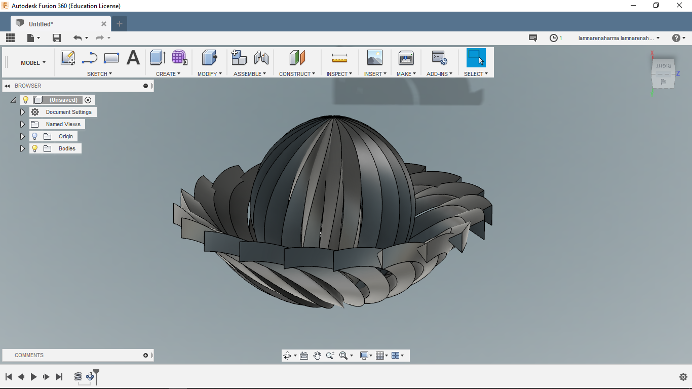
Personal Assignment-Designing and Printing
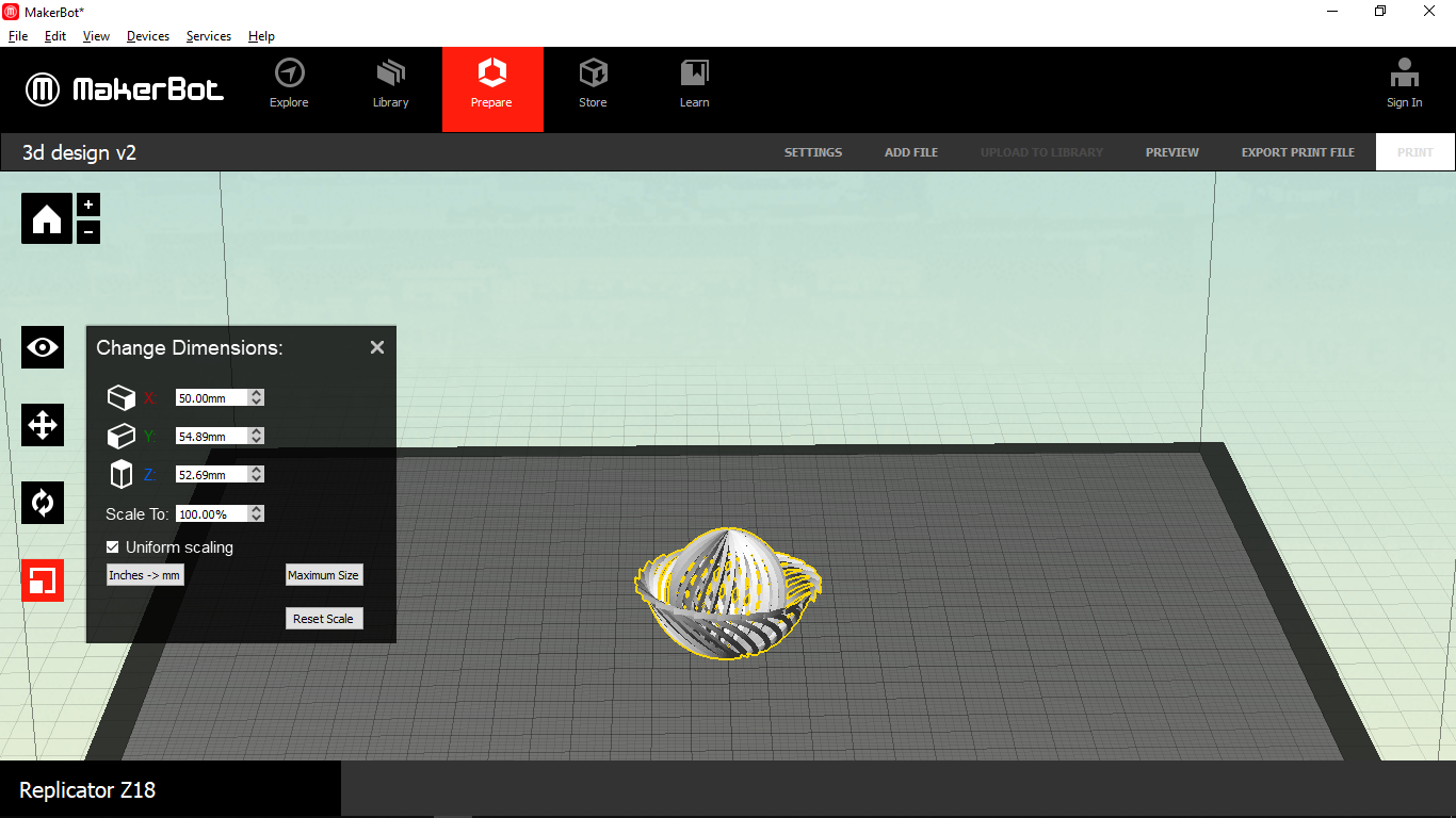
This is my design which can be used to create amazing lighting patterns in a room by inserting some LEDs inside.
I designed this model in Fusion360. I chose this because we had to design something which can’t be created by subtractive manufacturing.
Steps
-
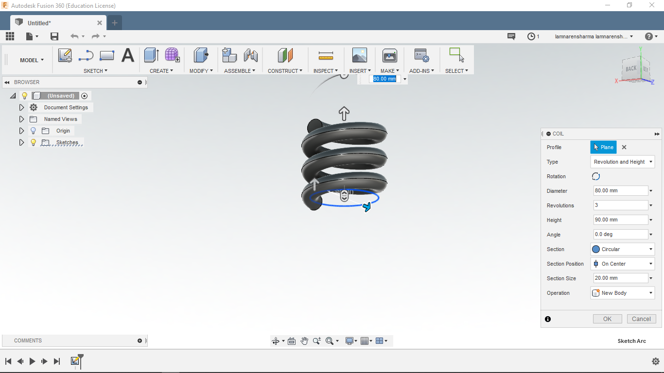
Make a coil using coil tool (create->coil) and use below settings.
-
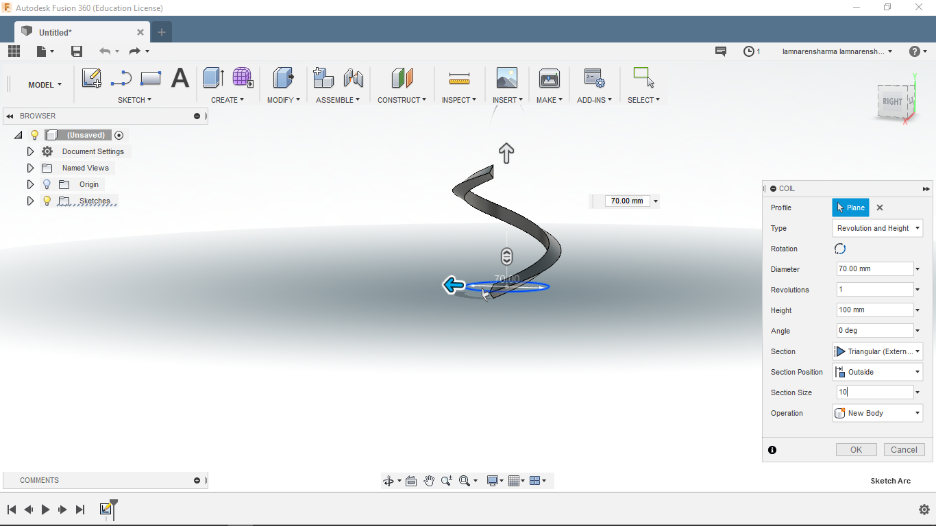
Change revolutions to 1
Section- Triangular(external)
Section Position- Outside
Section Size- 10
-
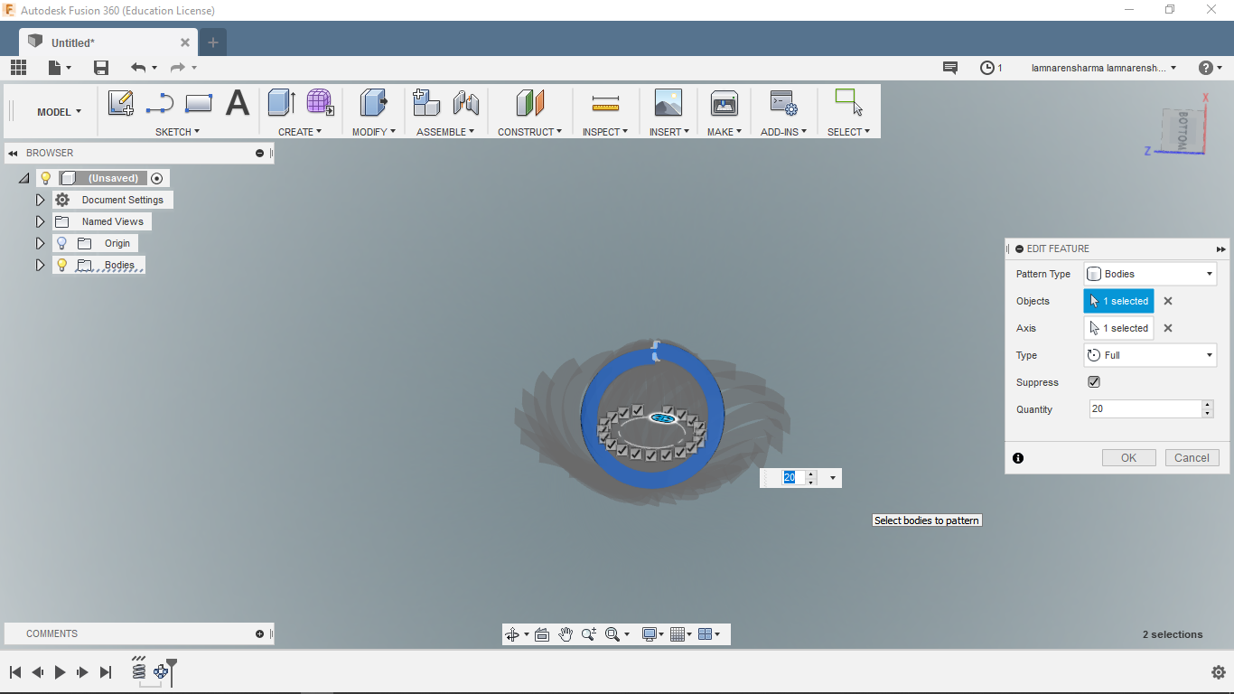
Next, Revolute this coil around the z-axis. Set quantity to 20.
Download the 3D model of lampshade.
Printing
Terms need to know before 3D printing
Supports: Used to hold the overhangs of the model. Choose Left or Right Extruder to print supports
Raft: Creates a raft below the model which can help with adhesion and tolerance for non-perfect
Wall: Creates a wall around the model to scrape oozing from the idle extruder. It’s suggested to
Brim: Expand the outline of model’s bottom layers to a Brim which helps anchor the edges of the model to the plate to avoid warping.
Resolution: Height of each layer.
Shell: Including outside shell quantity.
Infill density: Determines the interior solidity of the model.
I used MakerBot Desktop software to slice the model and export it to 3D printer for printing.
Steps
- First, Import the 3d model. MakerBot slicer supports .obj, .stl and .thing formats.
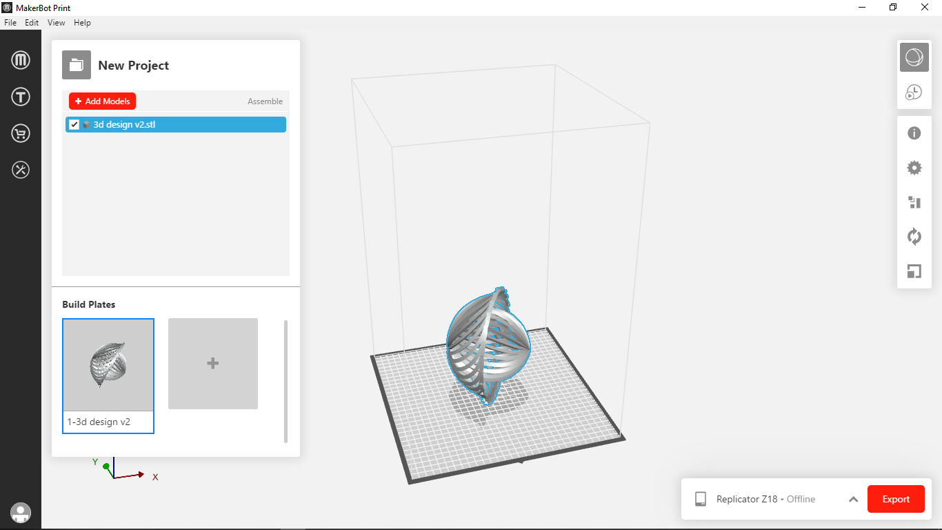
- If required, change the orientation. The model should be placed in such a way that it can be printed with minimum supports.
- Settings-
Temperature- For PLA, the temperature should be in the range of 190-220. I used 215 degree which is the default temperature setting in MakerBot
Infill- 10-15%
Raft- Enabled
Supports- Enabled
Resolution- Standard
Click here to learn about more parameters.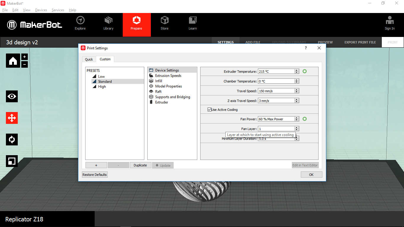
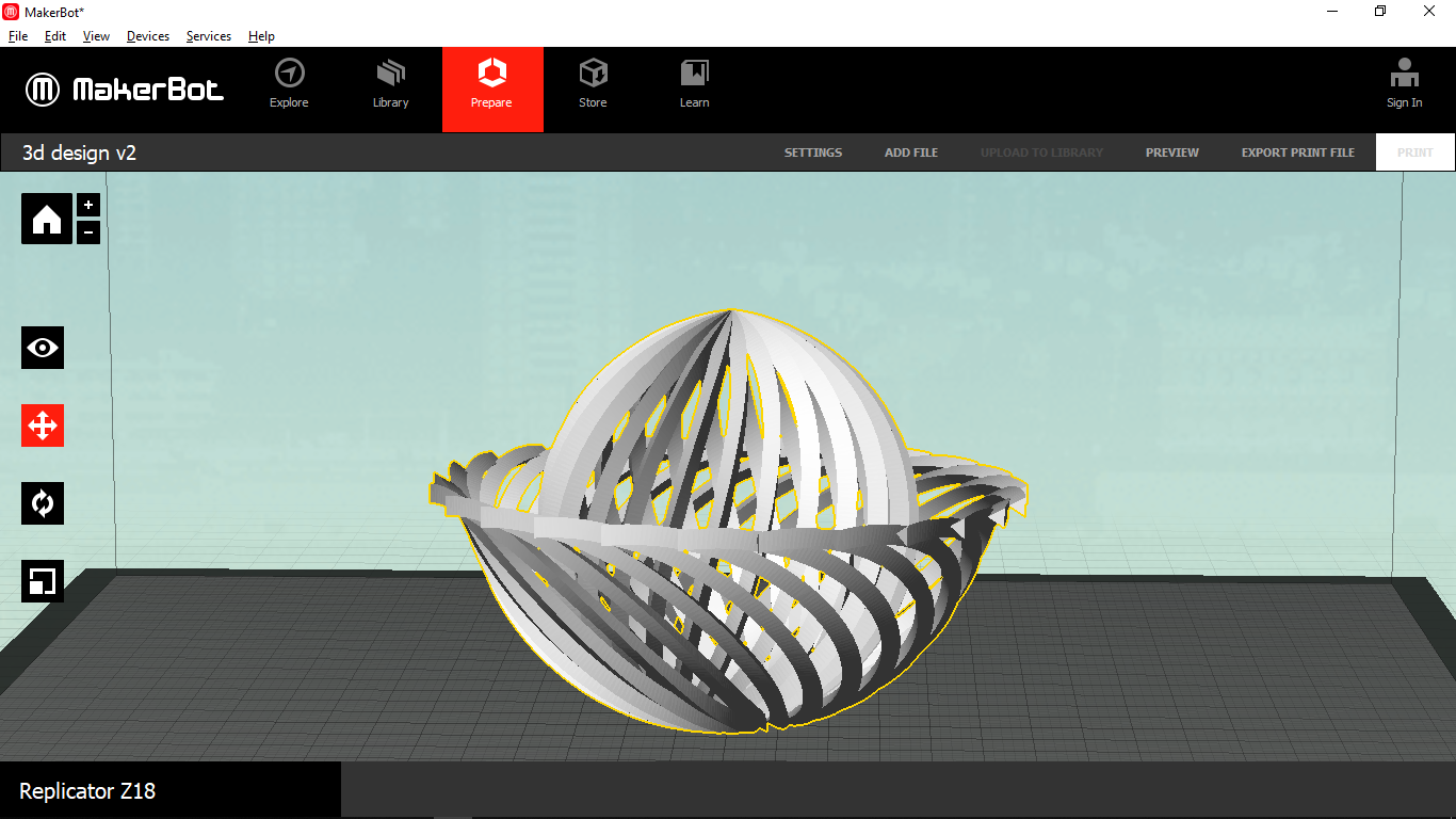
- Preview the file. It tells us the estimated material and printing time.
The estimated printing time for this model is about 12 hours 30 minutes.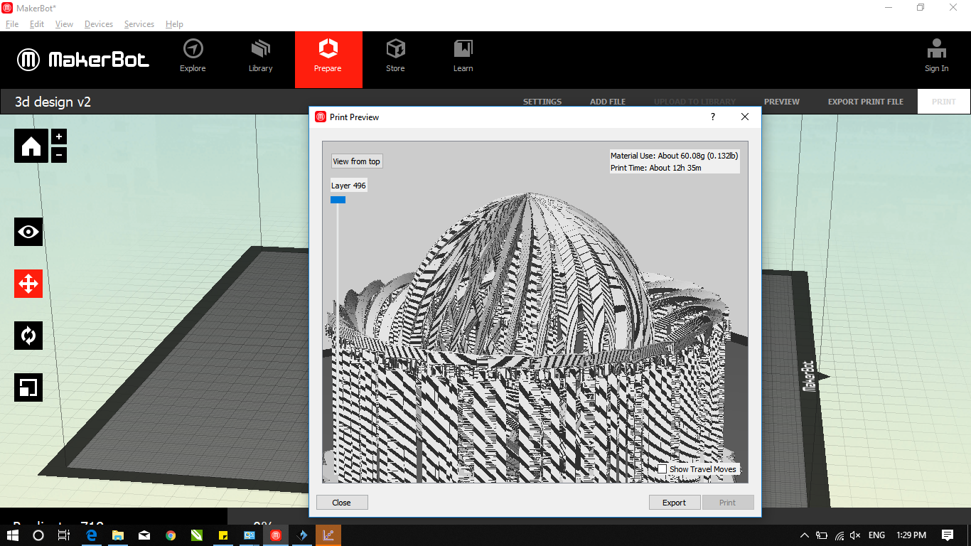
- I scaled it down for the test print. The estimated time for the scaled model was about 1 hour and 30 minutes.
- Then, export the file and save it on USB. Now the model is ready to be printed.
Printed model
The test print didn’t come out as expected. The surface was not smooth and there was too much oozing. This can be fixed by reducing the temperature by 5-7 degree and increasing retraction distance.
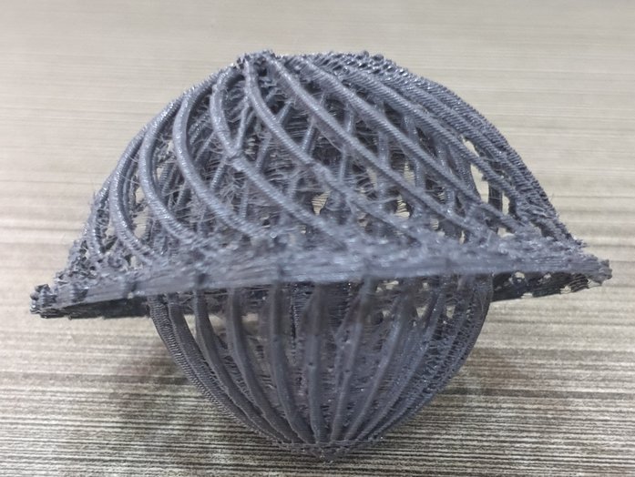
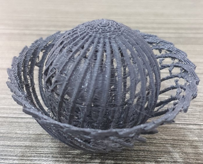
I will print the actual size model in the future and update here.
3D Scanning
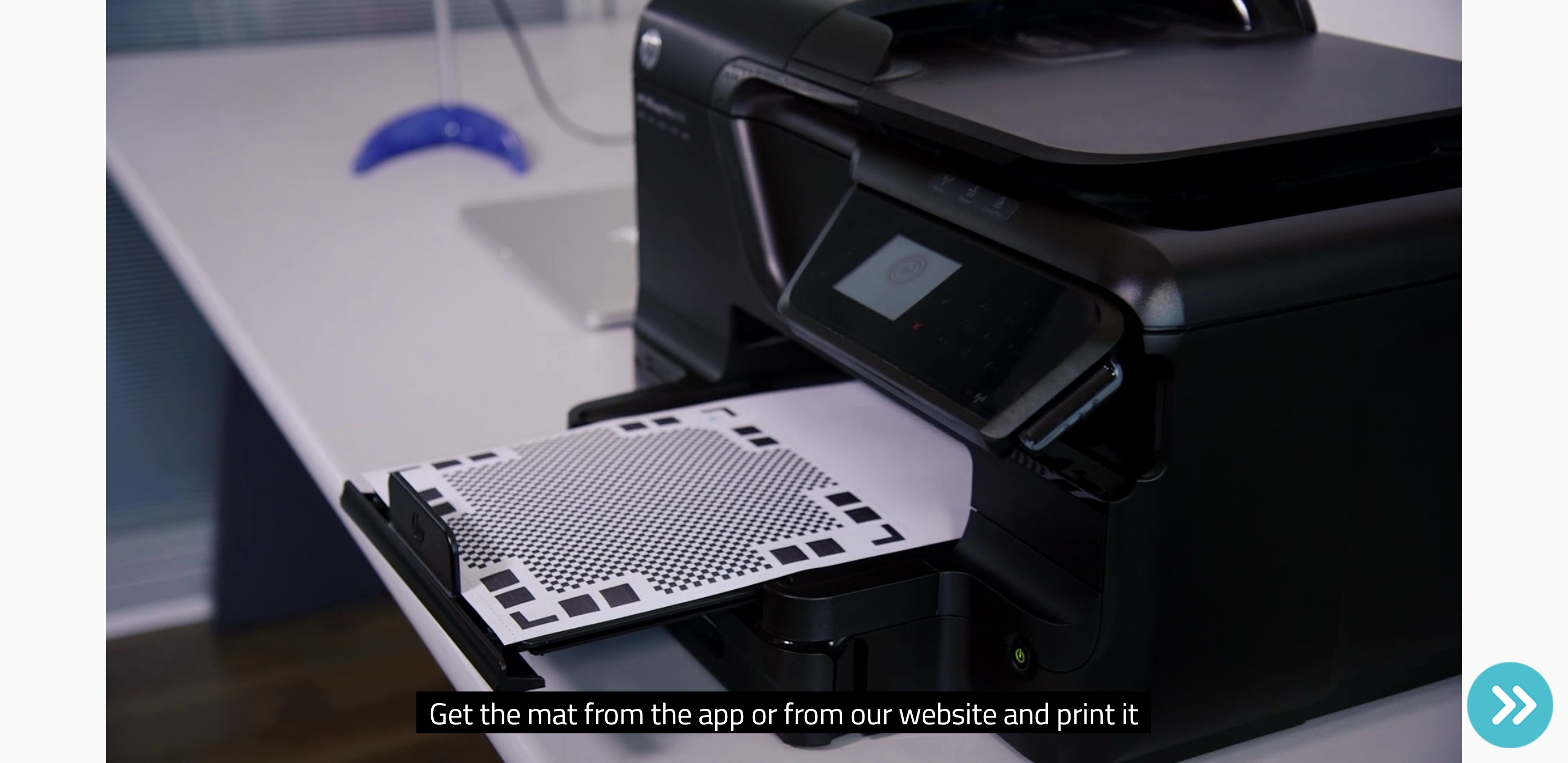
I used Qlone android app for 3D scanning.
Steps
- First, get the mat from the app or their website and print it.
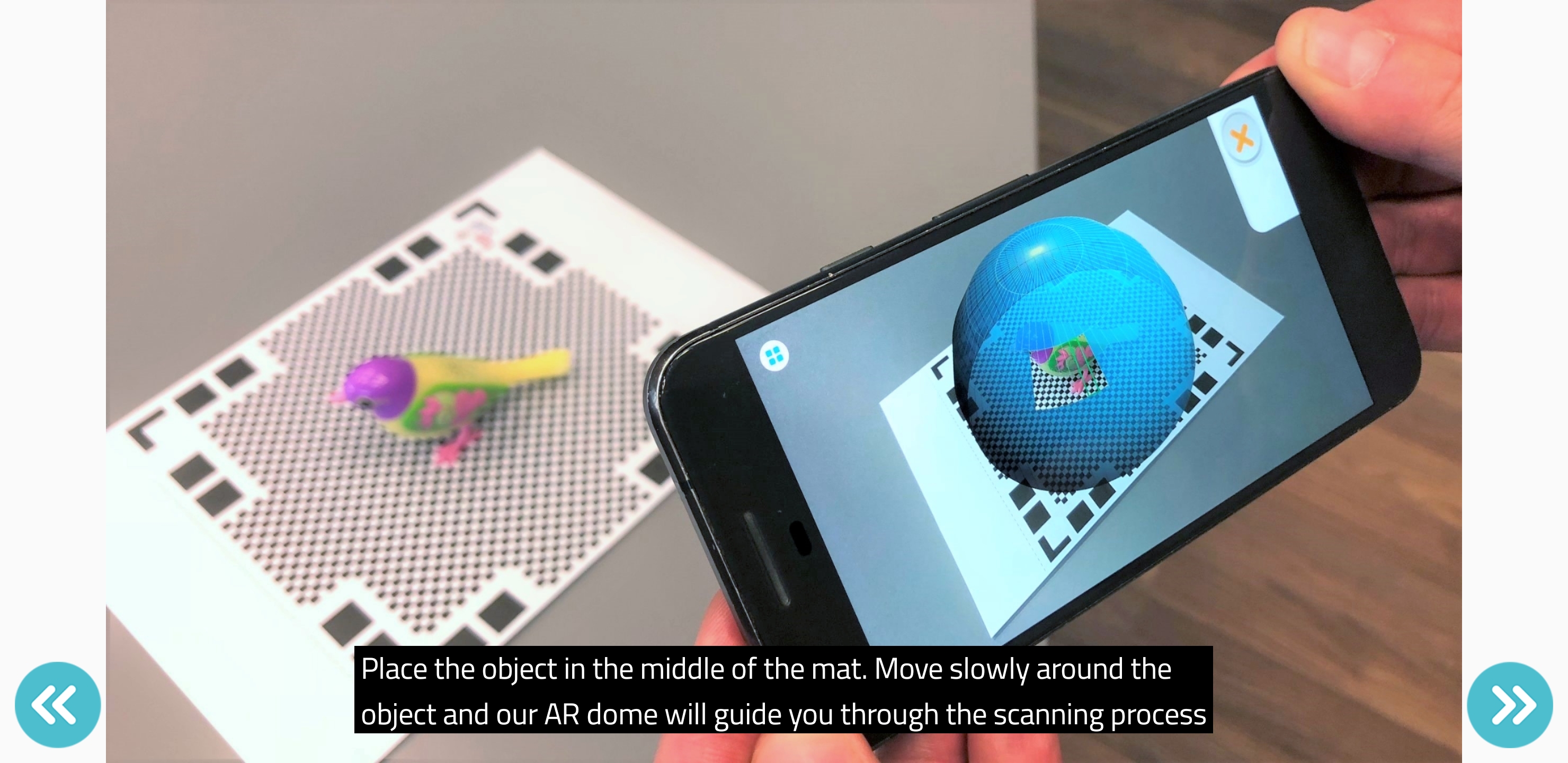
- Place the object in the middle of the mat.
- Move slowly around the object and the AR dome in the app will guide through the scanning process.
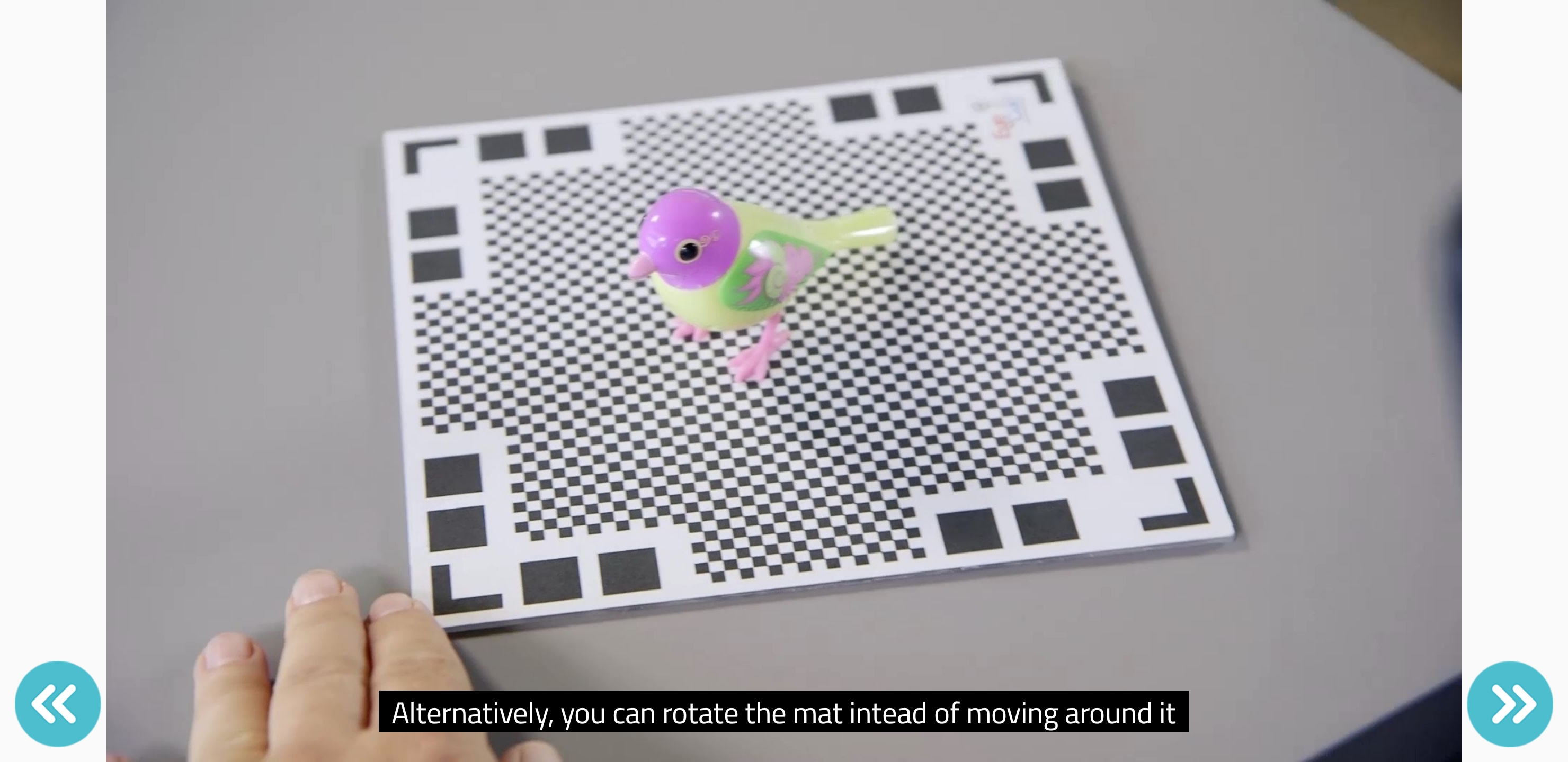
- Also, you can rotate the mat instead of moving around it.
I scanned a PCB and a 3D printed pumpkin.
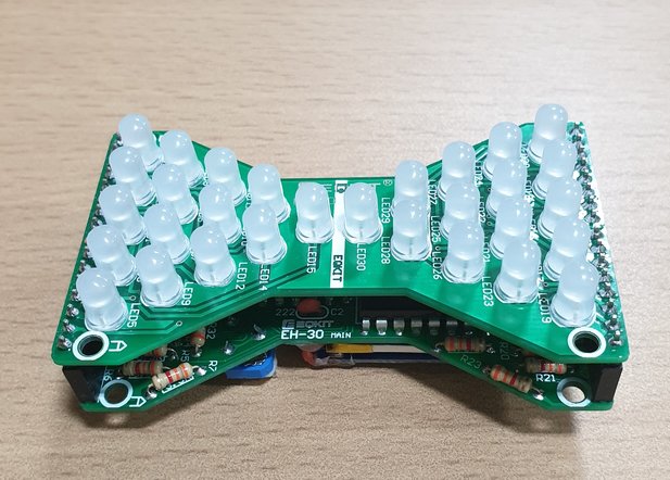
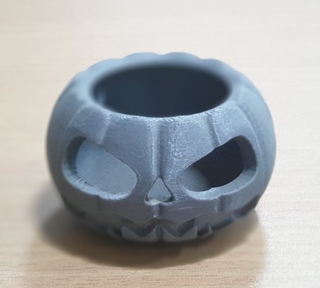
And below are the scanning results.
Then I used X-Box Kinect sensor for scanning.
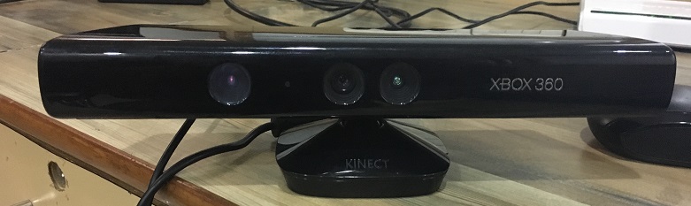
Steps
- Download and install the kinect for windows SDK.
- Plug in your Kinect sensor and wait for windows to detect the device.
- Download SKanect, 3D scanning software.
- On the first screen, feed the setting like scene, bounding dimensions, path to save the file, etc.
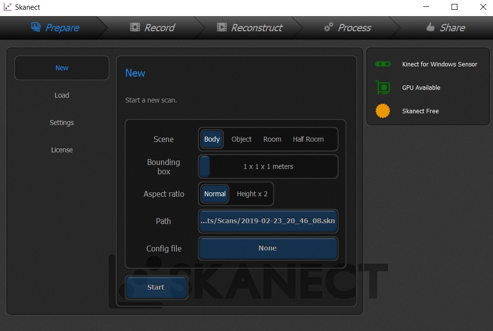
- Then start recording by clicking on record.
I tried to scan myself and the results were not very satisfying. The details were missing and it model has some holes also.
Design files
- Download the design filed for this week from here.
Learnig outcomes
- I learned about various 3D printing technologies.
- Learned to scan objects using a mobile phone and the kinect sensor.

This work is licensed under a Creative Commons Attribution-NonCommercial-ShareAlike 4.0 International License.