14. Networking and communications
Assignment
-
Individual assignment:
Design, build and connect wired or wireless node(s) with network or bus addresses -
Group assignment: Send a message between two projects
Introduction
Communication Protocol
If two people want to talk to each other then they use mobile phone or telephone which use some kind of protocols (a stack of rules), and each protocol have their one merits demerits, like Mobile phone use GSM / CDMA standard /protocol so the benefit of this is, it provides us to freedom of mobility, we can talk to people from any place but there are the issue of batter, signal BW and power, etc…. Same as telephone provide us good voice quality but its not portable.
So the first thing is communication protocols are essential to communicate with each other and for that, there are so many protocols and each has their merits and demerits and application area.
Similarly In Embedded system
Embedded system is an application specific, electronic system design with the help of some kind of processor or controller, and it takes input from the physical world with the help of Sensor and gives the desired output. So here in embedded systems, sensors want to communicate with processors/controller same, all components of an embedded system (Memory, IO devices, controller, etc) needs to communicate with each other to work properly.
In Embedded systems, various type of protocol is available and used according to the application
Wired protocols:
- SPI
- I2C
- CAN
- UART
- AMBA
- RS232 etc..
Similarly, wireless communication protocol is also used in various applications like
- zigbee
- Bluetooth
- MQTT etc…
Each protocol has its own significance.
I2c - For on chipboard communication between ICs and microcontroller, suitable for short distance communication on the PCB circuit board.
SPI - Most relevant protocol for high-speed communication, For example, SD card in mobile makes use of SPI for high-speed data transfer.
UART - Asynchronous serial communication preferred for communication between two devices. RS232 and RS485 are the preferred ones.
CAN - For Automobile communication
USB - for device storage applications
1 wire - Similar to I2c but faster when compared to i2c.
I set up communication between my controllers using the I2C protocol.
I2C communication
I2C (Inter-Integrated Circuit bus), originally developed by Phillips (now NXP Semiconductor) and also commonly known as TWI (Two Wire Interface) by Atmel and other companies who don’t want to get into trademark issues, is a two-wire synchronous serial bus. Let’s take a look at what each of those words means:
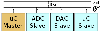
Two wire - This one’s easy, I2C uses two wires (in addition to ground, of course!) They’re called SDA (serial data) and SCL (serial clock). These are wired in an open-drain configuration, which means that the outputs of all connected devices cannot directly output a logic-level 1 (high) and instead can only pull low (connect to ground, outputting a 0). To make the line go high, all devices release their pull on the line and a pull-up resistor between the line and the positive rail pulls the voltage up. A good pull-up resistor is 1-10K ohms, low enough that the signal can be seen as a high level by all devices but high enough that it can easily be shorted out (pulled down) and not cause damage or significant power usage. There is one pull-up resistor on SDA and one on SCL.
Synchronous - This means that data transfer is synchronized via a clock signal that is present to all connected devices. This is generated by the master. To contrast, an asynchronous serial system does not have a clock signal. Instead, it uses a pre-determined time-base, or baud rate. An example of the asynchronous serial is RS-232 (the common serial port on many computers).
Serial - Data transferred serially means that one single bit is transferred at a time over a single wire. To contrast, parallel data transfer has multiple wires, each carrying one bit, which is all sampled at once to transfer multiple bits in parallel.
Bus - A bus is a system which allows many devices to communicate with each other over a single set of wires. While it may be called a bus, USB is not a true bus at the hardware level, as connecting multiple devices require a hub. A bus such as I2C allows new devices to be added simply by attaching their SDA and SCL connections to the existing line. Busses (I2C, USB, PCI, etc) all use an addressing system, in which each device has a unique address. An address, in this case, is simply a binary number, and all messages to that device must be sent with that address.
I2C Protocol
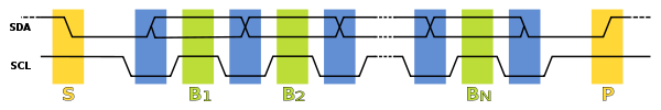
In normal state both lines (SCL and SDA) are high. The communication is initiated by the master device. It generates the Start condition (S) followed by the address of the slave device (B1). If the bit 0 of the address byte was set to 0 the master device will write to the slave device (B2). Otherwise, the next byte will be read from the slave device. Once all bytes are read or written (Bn) the master device generates Stop condition (P). This signals to other devices on the bus that the communication has ended and another device may use the bus.
Most I2C devices support repeated start condition. This means that before the communication ends with a stop condition, the master device can repeat the start condition with address byte and change the mode from writing to reading.
Schematic
Master
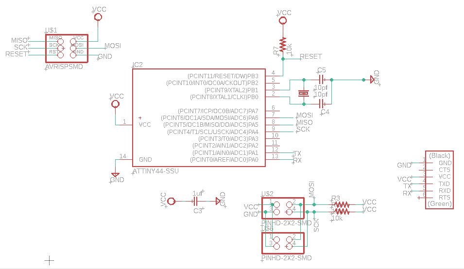
Slave

Download Master schematic
Download Slave schematic
Eagle Board
Master
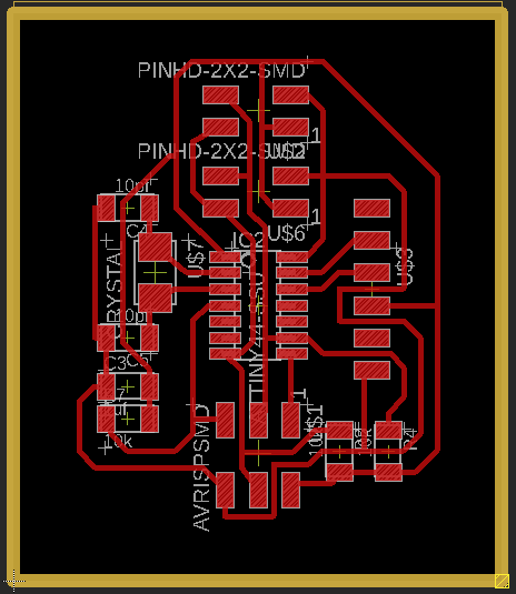
Slave
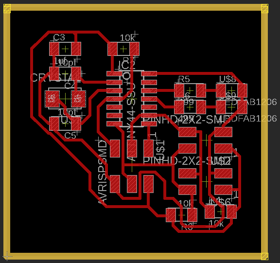
Download Master Board
Download Slave Board
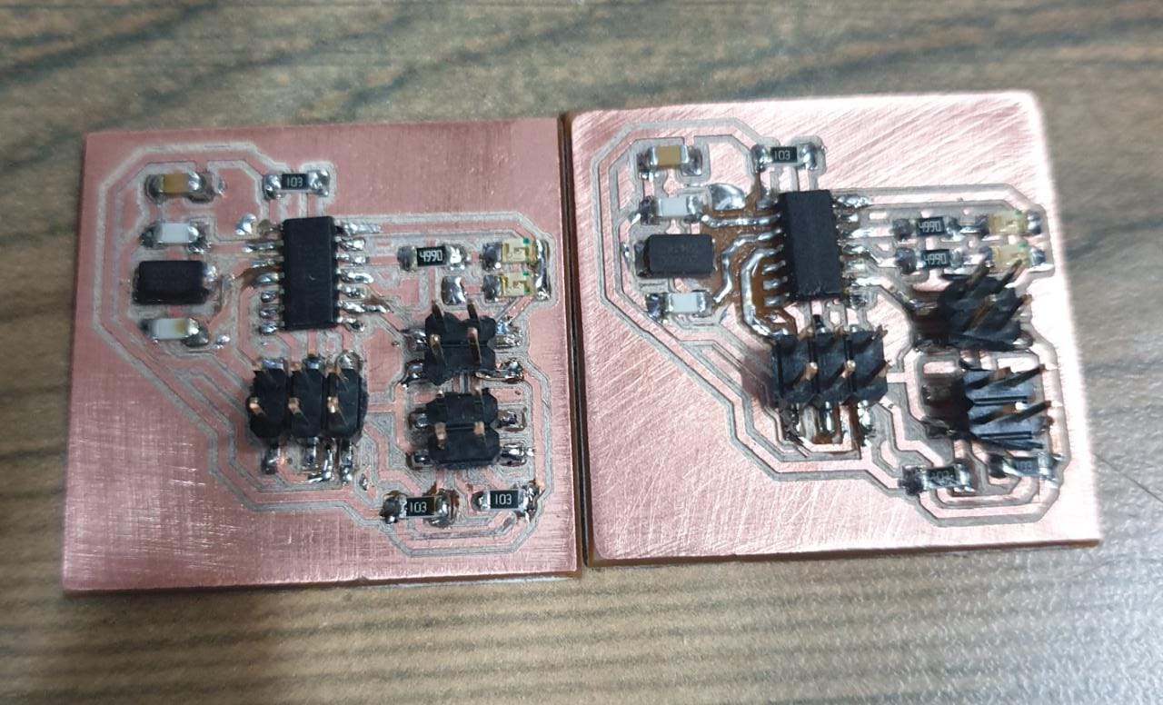
Milling and Soldering
Master
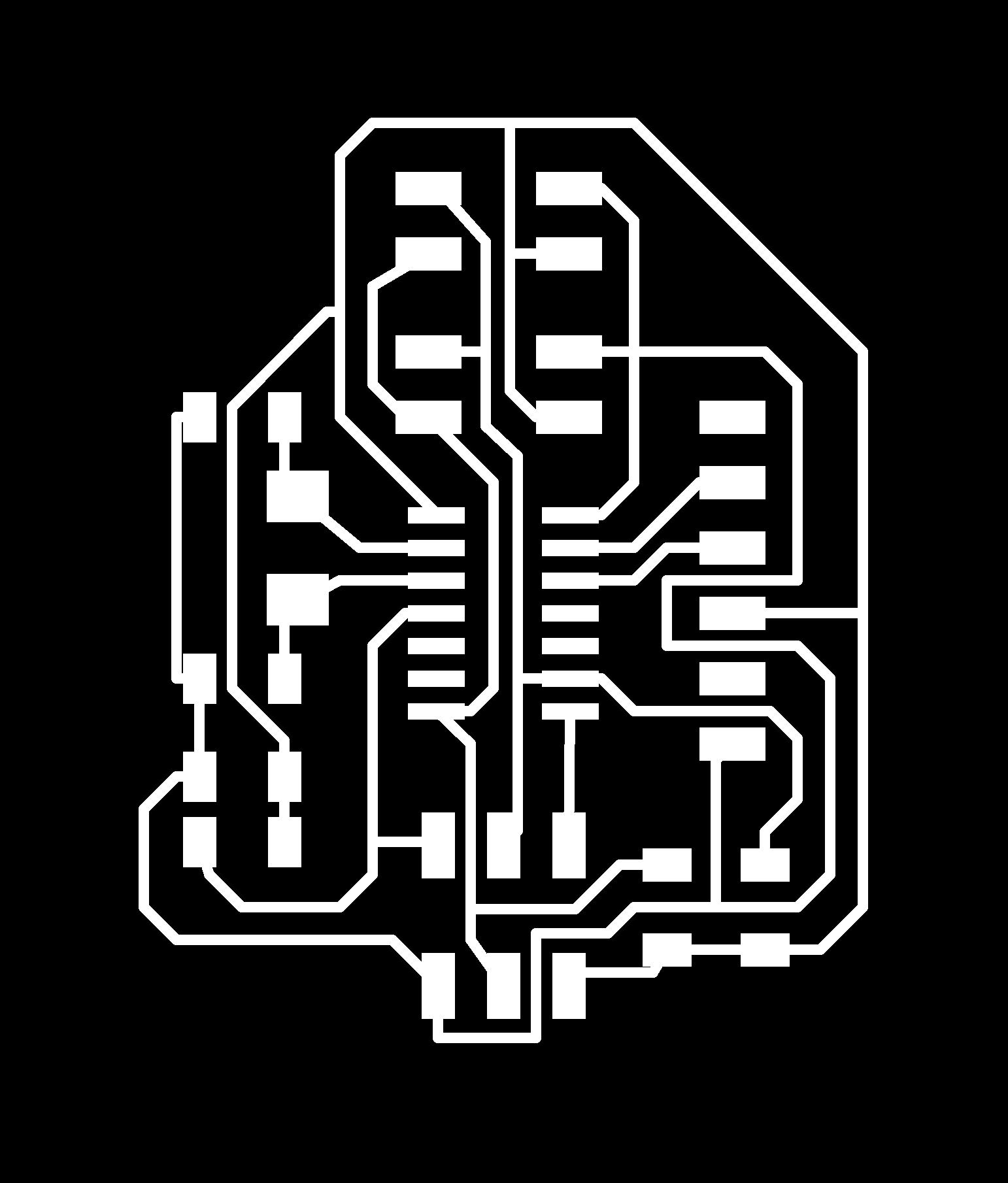

Download Master traces
Download Master outline
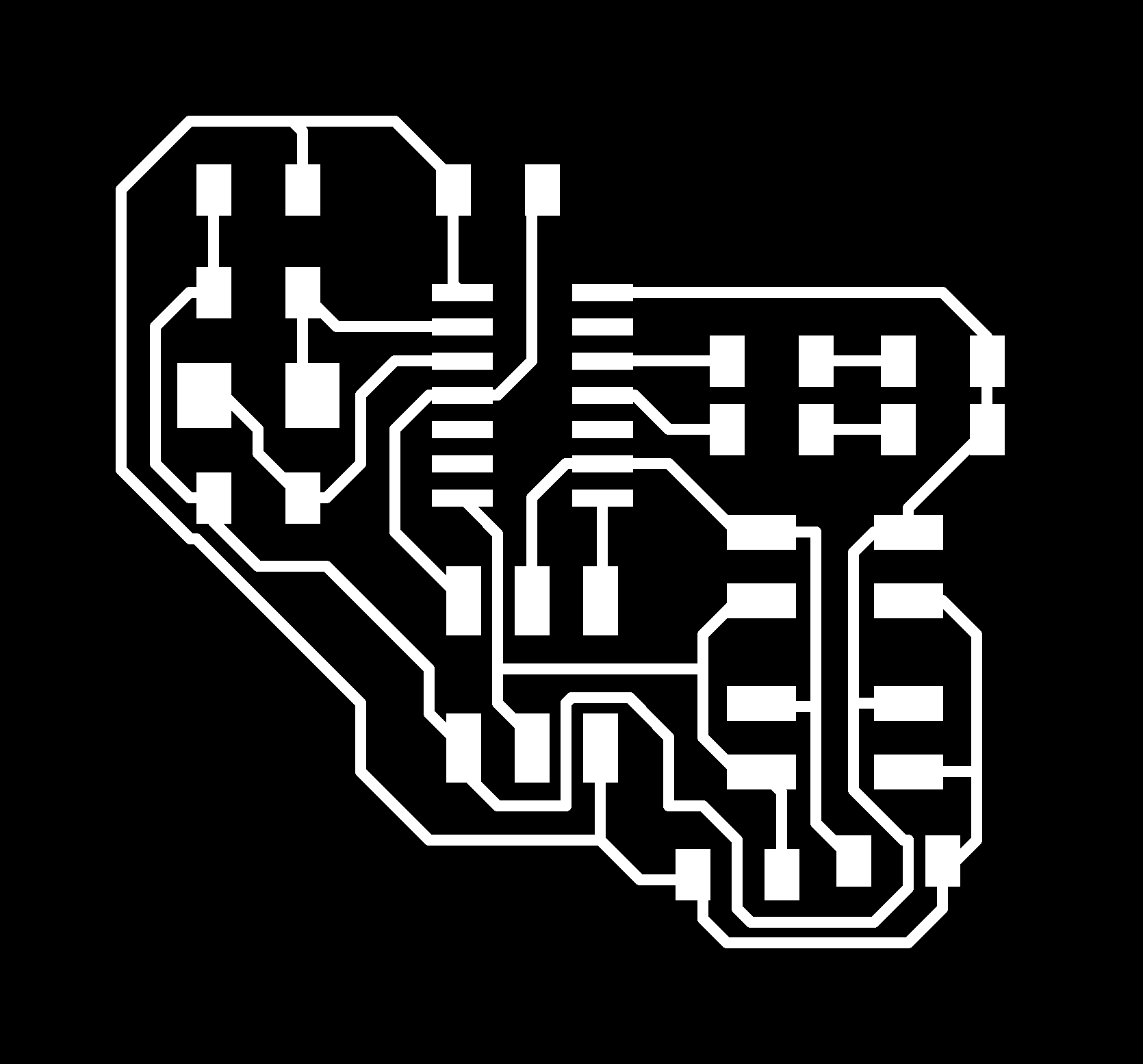
Slave


Download Slave traces
Download Slave outline
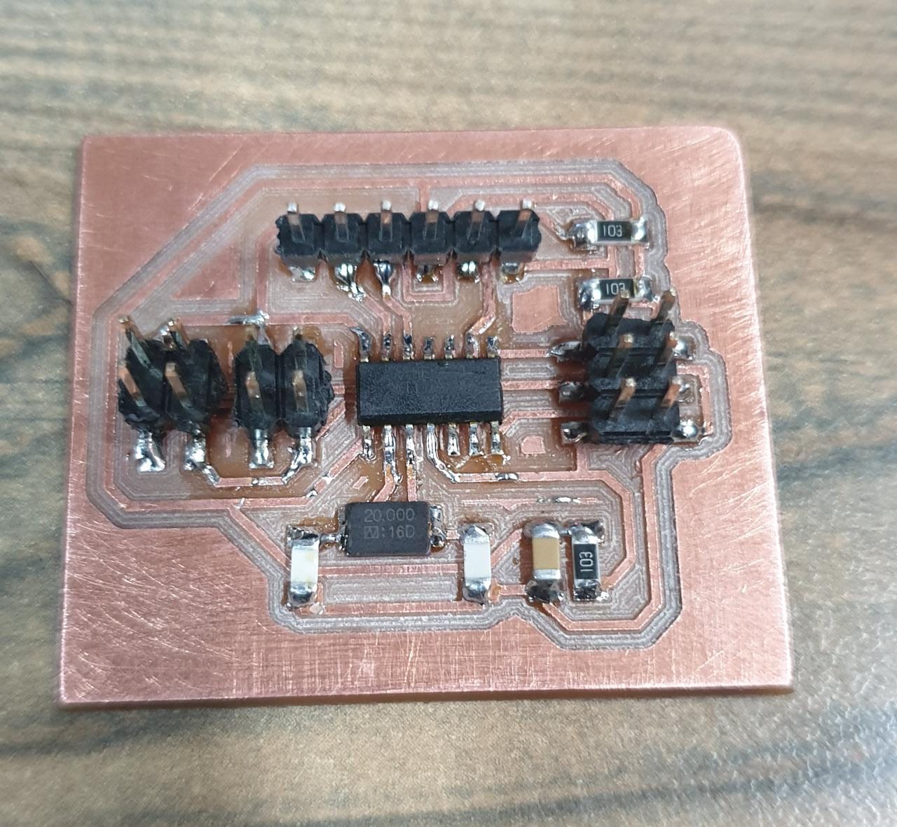
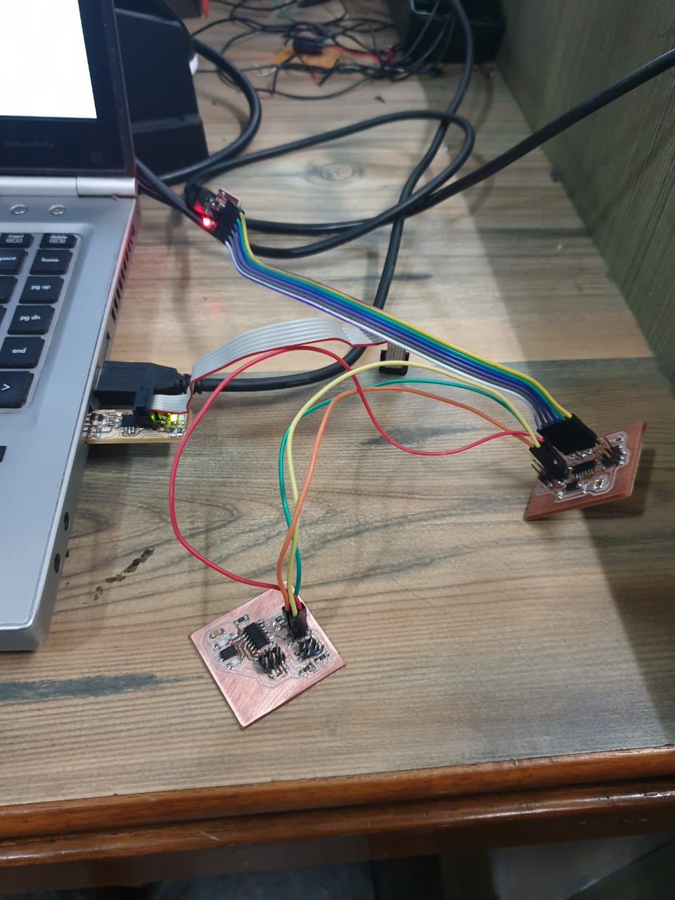
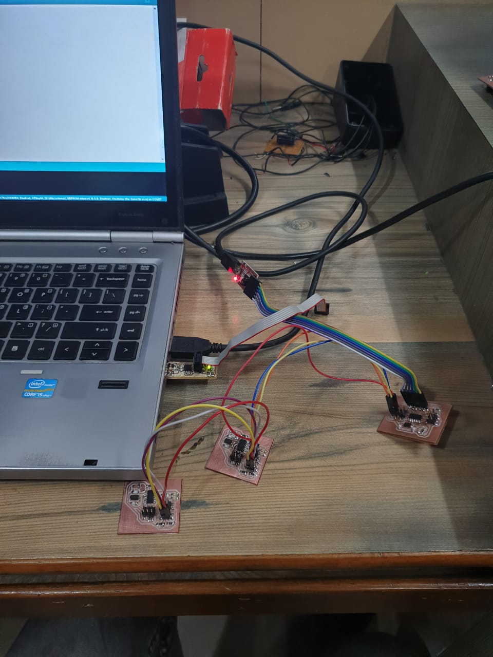
Connections
After soldering, we need to connect all the boards together. And this is how we do that- the SDA and SCL pins of the all the boards are connected together. We have already connected the 10K resistors in between Vcc and the sda and scl pins in the schematic.
Programming
Master Code
#include "Wire.h" // This is I2C library
#include "SoftwareSerial.h" // This is used for making rx tx pins using software
#define Rx 1
#define Tx 0
SoftwareSerial myserial(Rx, Tx); // declared Rx and Tx Pins

void setup() {
  Wire.begin(); // I2C communication Started
  myserial.begin(9600); // Serial communiation Started
  myserial.println("Communication Started");
}

void loop() {
  char d; // Character type declaration to store a character.
  if (myserial.available() > 0)
  {
    d = myserial.read(); // Read serial and store its value in variable d.
    if (d == '1') {   // Now transmit data over the I2C lines according to the cases.
      Wire.beginTransmission(1); // Communication started with first node\
       myserial.println("send ");
      Wire.write(1); // Value sent over the channel
      Wire.endTransmission(); // Communication Ended
      myserial.println("send :- ");
      myserial.print(d); // Print on Serial Monitor

    }
    if (d == '2') {             // Same of others.
      Wire.beginTransmission(1);
      Wire.write(2);
      Wire.endTransmission();
      myserial.println("send :- ");
      myserial.print(d);
    }

     if (d == '3') {             // Same of others.
      Wire.beginTransmission(2);
      Wire.write(3);
      Wire.endTransmission();
      myserial.println("send :- ");
      myserial.print(d);
    }


  }
  delay(10); // Delay to make sure whole CPU is not consumed.
}
Slave 1 Code
#include <Wire.h>
#define led PA1
void setup() {
Wire.begin(1);

Wire.onReceive(receiveEvent);
pinMode(led, OUTPUT);
}
void loop() {
delay(100);
}
void receiveEvent(int howMany) {
int x = Wire.read();
if (x == 1)
{
digitalWrite(led, HIGH);
}
if (x == 2)
{
digitalWrite(led, LOW);
}
}
Slave 2 Code
#include <Wire.h>
#define led PA1
void setup() {
Wire.begin(2);

Wire.onReceive(receiveEvent);
pinMode(led, OUTPUT);
}
void loop() {
delay(100);
}
void receiveEvent(int howMany) {
int x = Wire.read();
if (x == 3)
{
digitalWrite(led, HIGH);
}
}
Download Codes
Master
Slave1
Slave2
Working video
Learning outcomes
- I learned a lot of things about the i2c communication.
- Successfully programmed the master and slave and set up communication between the master and the slave.

This work is licensed under a Creative Commons Attribution-NonCommercial-ShareAlike 4.0 International License.