FP.1. Definition
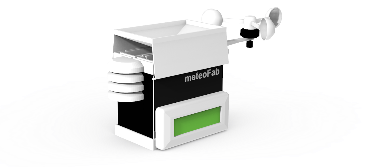
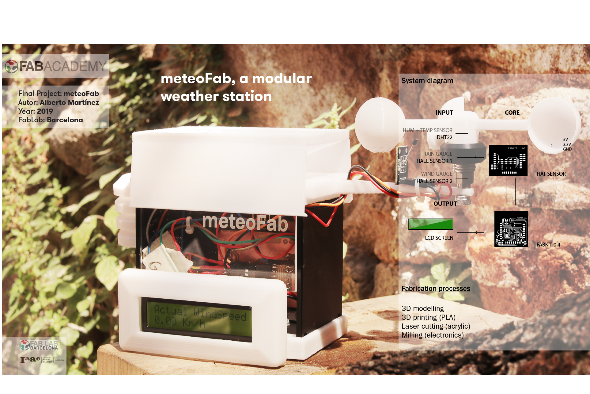
My final project is based on a superlocal weather station for educational learning. Designed as a starter kit for environmental data collection, the device gathers realtime information from 4 different weather sensors: a wind gauge, a rain gauge, a thermometer and a humidity sensor.
This kit is designed to be used in rural areas where there is a profound lack of realtime weather information not just average, or maximum and minimum rates of this environmental data. In addition, having this information about their local weather would help them to anticipate to environmental changes, even aware from climate change and how it affects to their crops what directly affects to their local economy.
The data collected by the system will be processed by a opensource board that can be replaced by a common ArduinoUNO, and will display this information on an LCD screen. Hopefully, a further update of this device could store this data in a removable miniSD card, or sent via WiFi or Bluetooth, or even the well-known low-power wide-area network called LoRa (it could reach distances up to 10km in rates below 50kbps).
FP.2. Video and slide presentations
Video Presentation
Slide Presentation
FP.3. Contents, processes and course assignments
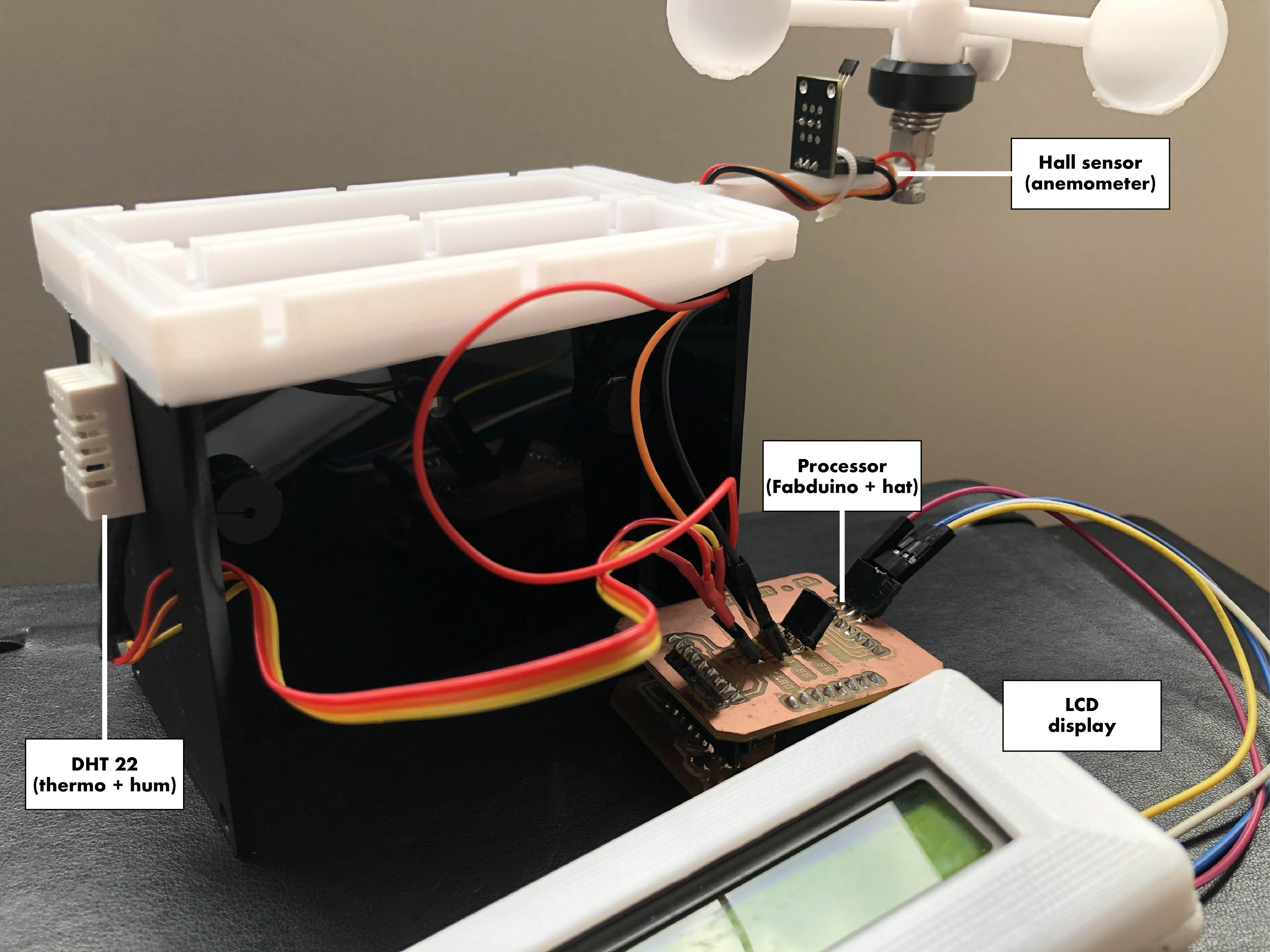
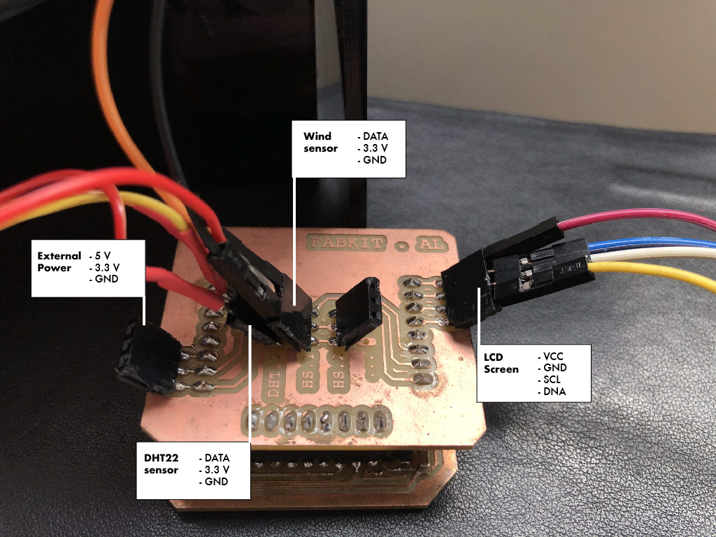
SYSTEM AND CONNECTIONS
This two pictures show the components involved on the system and its connections. A fabduino processor, a hat sensor module to connect the sensors and output on the LCD display:
CONTENTS AND PROJECT DEVELOPMENT
I used different processes to design and produce this device. All the steps and workflow of every process worked is explained either on Wk.20 Project Development assignment or in the respective theme exercise that will be linked below. After the research and ideas generation, I started designing the model in Fusion360 and then switched to CreoParametric to create the 3D models.
+ 3D model:
- Representing the whole device, including every mechanical part (Wk20)
- To create the 3d printing files (Wk20)
+ Laser cutting:
- Cutting and rastering acrylic walls (Wk20)
+ 3D printing:
- Upper and lower bases of the case (Wk20)
- Sensors coverings, mechanical activators, and clipped joints for each module (Wk20)
+ Electronics Design:
- Fabduino Al (Wk11 | Wk20)
- Hat input-output shield (Wk12 | Wk20)
+ Electronics Production:
- Fabduino Al (Wk11 | Wk20)
- Hat input-output shield (Wk12 | Wk20)
-
for the case, joints and hardware production should be made by 3D printing, molding and laser cutting.
For the electronics production, I will use PCB milling, components soldering, programming and debugging.
The rest of the project will include software programming and network communication.
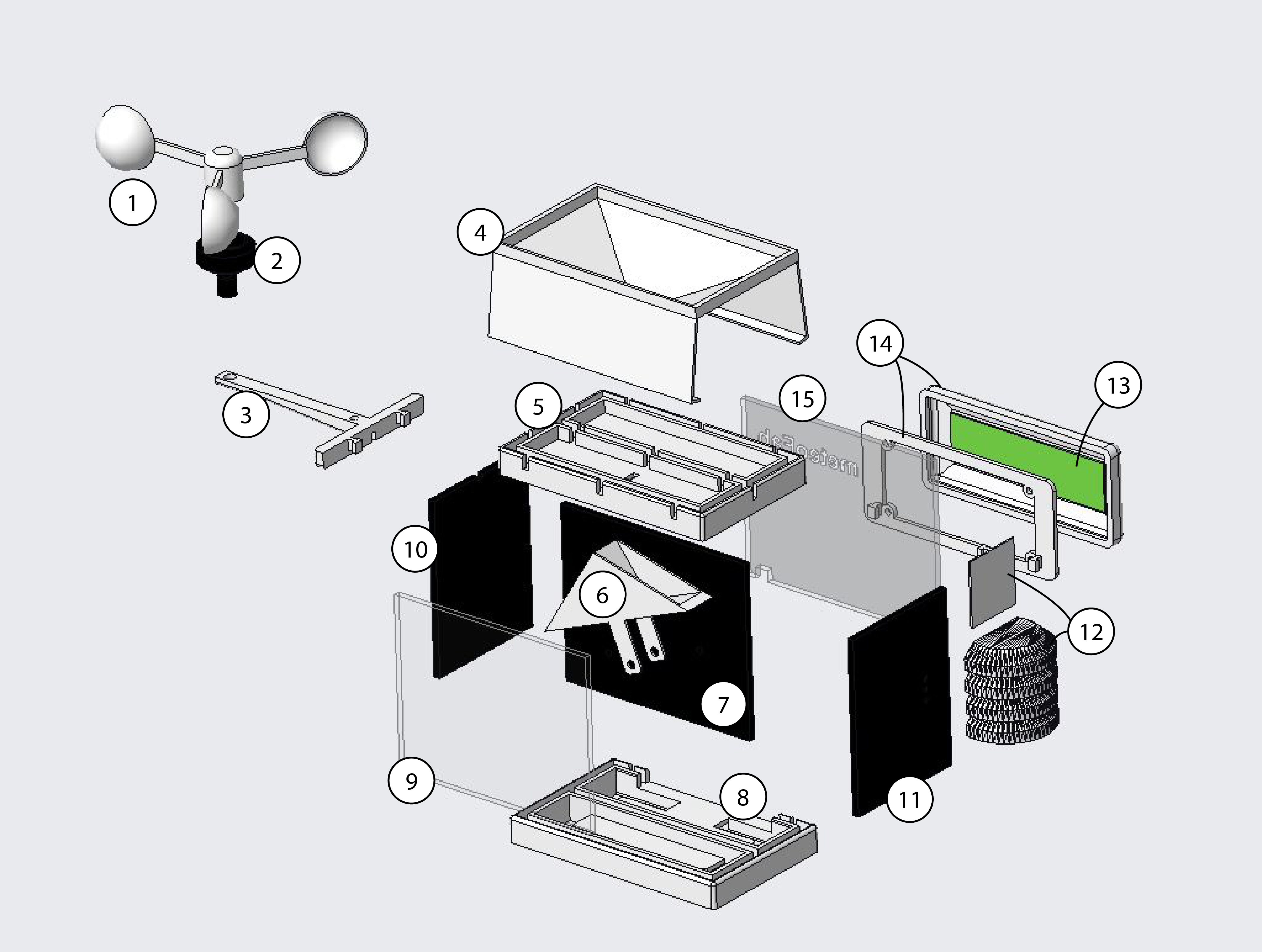
1. Anemometer
2. Bearing axis
3. Anemometer arm
4. Rainwater basin
5. Upper base
6. Pluviometer
7. Middle wall
8. Lower base
9. Back wall
10. Right wall
11. Left wall
12. Stevenson screen + clip
13. LCD screen
14. Screen case + clip
15. Front wall
FP.4. Bill of materials (BOM)
This would be the whole material and components list and its cost:
Material
+ Acrylic plastic
- Acrylic 3mm pieces (black) - 1,50E
- Acrylic 3mm pieces (transp) - 0,80E
+ 3D printed parts (Cura ref.)
- Top base - 2,20E
- Bottom base - 2,10E
- Screen case - 0,55E
- Stevenson screen - 0,40E
- Pluviometer (arrow) - 1,20E
- Pluviometer (basin) - 2,30E
- Anemometer (arm) - 0,85E
- Anemometer (blades) - 1,30E
+ Mechanical parts
- Magnet (x2) - 0,60E
- Bearing - 1,20E
+ Electronic components
FABDUINO
- Microcontroller: ATMEGA 328P(+) - 1,87E
- Resistor: 499 ohms(+) - 0,09E
- Capacitor (unpolarized): 10 uF(+) - 0,16E
- Capacitor (unpolarized): 1 uF(+) - 0,24E
- Capacitor (unpolarized): 0.1 uF(+) (x2) - 0,39E
- Resonator: 8 MHz(+) - 0,34E
- LED: 1206SMD(+) - 0,31E
- Switch: 6 mm(+) - 0,93E
- Header: 6 pin(+) - 0,53E
- Pin header: 8 pin(+) - 0,86E
HAT SENSOR SHIELD
- DHT22(+) - 8,71E
- Hall effect sensor(x2)(+) - 1,84E
- Female Header 10pin (x3)(+) - 2,10E
- LCD Display + I2C module(+) - 6,99E
--------------------
Total cost: 40,10 Eur
FP.5. Project Status
What is working:
- Thermometer. Temperature data in Celsius degrees measured by DHT22 sensor.
- Hygrometer. Humidity percentage measured by DHT22 sensor.
- Anemometer. Windspeed in km/h measured by the hall effect sensor.
- LCD display. All 3 sensors' data displayed on the LCD screen every 2 seconds.
What is still not working:
- Pluviometer. Raingauge in mm measured by the hall effect sensor.
FP.6. Original design files
Here there are the original design files for:
- CAD files
- Lasercut 2D drawings
- Eagle boards/schematics
- Code sketches
Here there is the legal code for the license I chose.

This work is licensed under a Creative Commons Attribution-NonCommercial-ShareAlike 4.0 International License