Week 10 - Moulding and Casting
Introduction
I wanted to have made an induction furnace by this point to utilise my raw aluminium ingots to do some metal casting. But alas my learning and time management (or lack thereof) has got in the way of this being completed in time.
I am going to try to cast some candles, or a candle based on a chess piece I designed for a CAD project quite some years ago.
I am getting into animation recently - I only went to take a picture of it to put here, but that quickly led to me popping the camera on a tripod, and spinning the lil model around.
Wax casting
Two Part Plaster Mould Instructable
I shall be attempting a casting later today using plaster and wax to try to make a candle in the shape of the knight piece.
I will need to make some wicks (not sure how I am going to actually add these to the candles yet, but baby steps)
CNC Milling Moulding Process
It is a requirement of the FabAcademy to produce a mould using the CNC mill, which will be used for the creation of a casted mould; in a two stage mould process to cast a part.
The initial milled part will provisionally be the part as realised, this will then be cast in a more flexible material to create a negative mould from which solid parts can be cast.
My initial plan is to create a charging dock for my apple pencil, this will require a place to hold the cable to pen adapter, a space for cable storage, and a function to allow the cable to be easily retrieved or stowed.
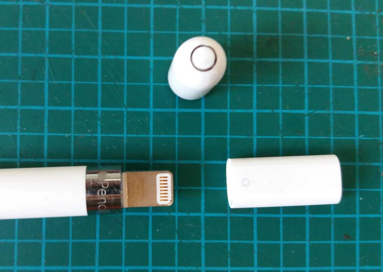
The pencil has a protective cap for the lightning port, this will need a place to sit - it appears to stay connected to the pencil via magnets.
The adapter has a small ring on one end this signifies the pen end - possibly a designed signifier to connect to the ring on the end of the pen.
Drawings
I start my design process as usual with some sketching out of the problem as the 3D visualisation space within my head quickly became overcome by trying to hand cabling.
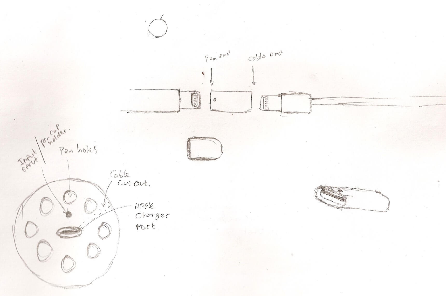
I sketched out the parts, outlined from the physical parts themselves just to get my mind in gear.
In the bottom corner is the first representation of my idea, pencil charger in the centre, with a little bobble for the end cap; and holes for other pencils/pens.
Solidworks
With an idea in mind I turned to Solidworks to generate a model.
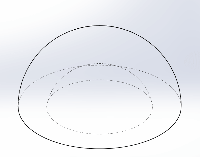
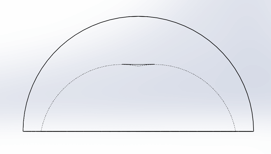
I started by creating a Dome from a circle a couple of lines and an arc - this was to have a different shape on the inside than the outside.
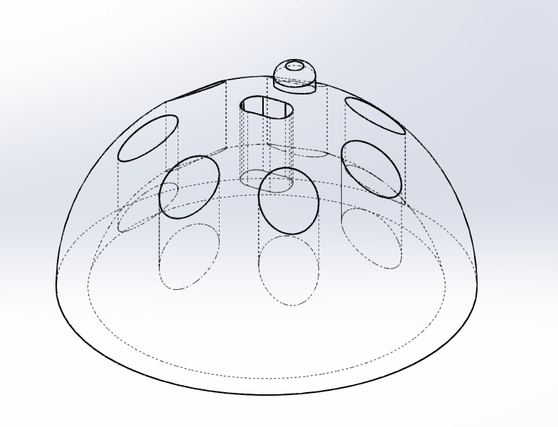
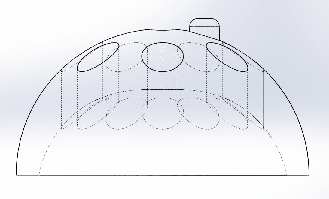
I then added a slot in the centre for the pencil charging cable adapter - the dome is 15mm thick, the adapter is about 19mm long, this will mean it pokes out either end ever so slightly.
The bobble for the pencil cap, and holes of 10mm diameter for other pens/pencils, they parse all the way through the part so things smaller than 10mm will sit on the surface, and things larger will get stuck and stick out.

I then duplicated the part file to edit into the negative to produce mould parts.
This needed to be done in two parts as this piece will need to be cast with a multi-part mould.
I basically reversed the model, flipping extrudes to cuts, and vice versa.
Machine code
I need to export the models as stls to produce machine code in another program. (I believe this stage is doable through fabmodules or mods, however Michael found using the software that came with the machine works well enough for our purposes.