3. Computer Aided design
This week, I worked on designing my final project in various CAD programs.
Inkscape
I’ve used Inkscape in the past, but I haven’t used it recently. When I did go and use it, it was actually quite difficult since I haven’t used it in maybe over 6 months.
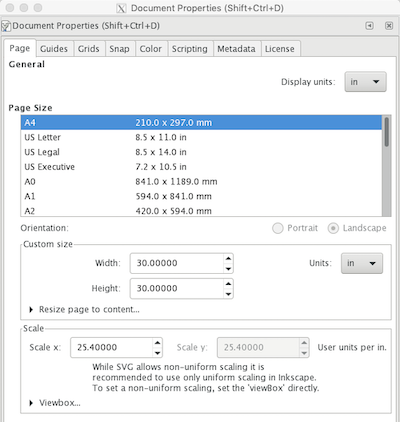
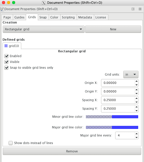
First, I edited the document properties and grid. I set the document to inches and made my page 30in x 30in. I knew going into it that the diameter of the largest circle in my design is 15 inches, so I doubled that to give myself room on the page. I generally create grids every 0.25in and a more dramatic grid every 4 (aka every inch). This is shown below.
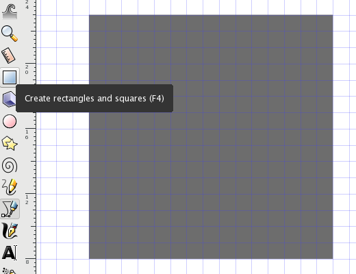
The first time I went to make the circle, I was quite confused as to how to size the circle other than following the grids. Since I didn’t want to count 15 grids, I created a rectangle, which I know how to set the size of. I made the rectangle 15in x 15in. Then, I made a circle inside of that rectangle by selecting one of the rectangle’s corners and dragging until the diagonally opposite corner.

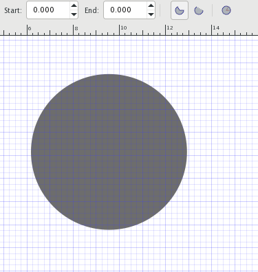
After drawing the circle, I saw that there were Start and End values. By changing these values, I learned what they did: they change how much of the circle is present/visible.

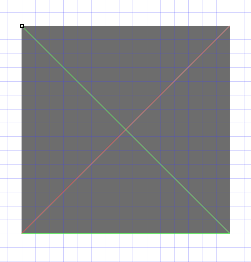
I also used the line tool to manually determine the center of a rectangle by drawing lines through the diagonals. The intersection of the two diagonals is the center point.
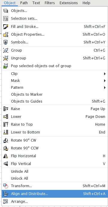
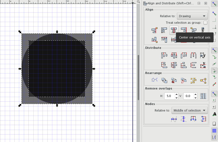
However, after manually finding the center of the circle, I remembered the Align and Distribute tool. It is found underneath Object, all the way at the bottom.
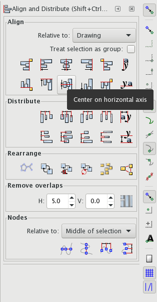
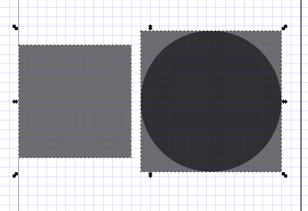
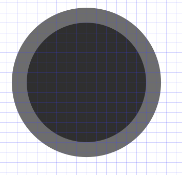
I then repeated the process of drawing the circle as done above with the 12in diameter circle and used the align and distribute tools to put everything in the center of the page. Here are the two rectangles and larger circle first on the horizontal centerline and then in the complete center of the page.
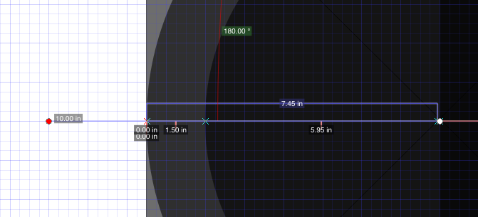
While I was using Inkscape, I discovered the measuring tool. Though I already know the measurements of everything in this specific design and this is a very simple design, the measuring tool may come in handy in the future, like in week 4.
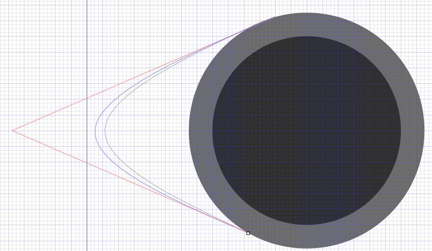
Finally, I created the spline that makes the distinctive teardrop shape. I created a line and chose its endpoint. Instead of letting go after pressing the endpoint, I kept clicking my mouse and watched as the spline curve developed.
Fusion 360
I am very comfortable with Fusion, but I haven’t used it for really complex designs since the summer. It took a little getting used to, but overall, I really enjoy working on Fusion. As a whole, this is probably the most complex design I’ve made on Fusion, especially because I worked quite a bit in the Modeling environment.
Base sketch
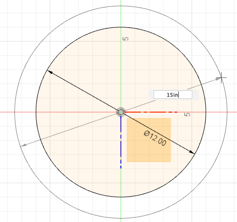
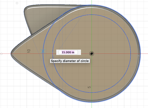
Using my hand drawn designs from week 1, I designed my record player in Fusion. I started by creating a sketch on the XZ plane and putting a circle at the origin. To create the circle, I used a keyboard shortcut by simply pressing C. This allowed me to place the point where I want to have the center of my circle and then type in what I want the diameter of the circle to be. I created two circles centered on the origin, one with a diameter of 12 inches (the diameter of a record). I wanted 1.5 inches of border outside of the record, so I made another circle with a diamter of 15 inches.
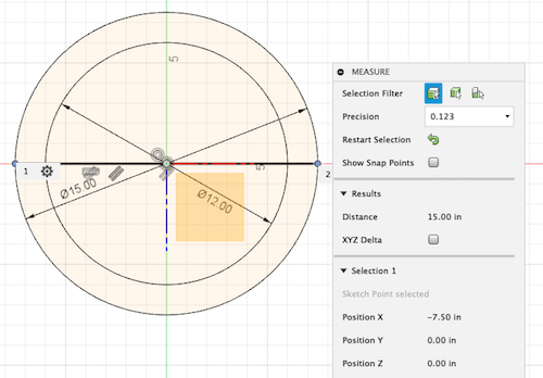
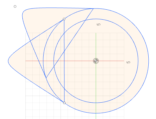
Using various other tools, like the line tool (which I personally prefer to use the L keyboard shortcut for) and conic curve tool, I created the final base of my sketch. I also used the measuring tool, which measures the distance between two points. If you press I on your keyboard, the measuring screen comes up and prompts you to select two points. It then gives you the distance between the points. While designing the base sketch, I realized that I wanted a second little tip thing so that the motor could be built into the record player and not just sit off to the side. You can see the difference in my Inkscape design from the one below.
Making it 3D
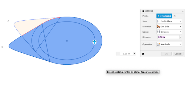
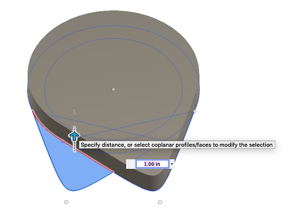
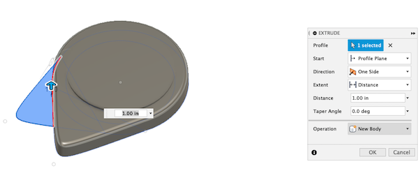
I used the Extrude tool (E) to make my model 3D. I extruded my main teardrop shape separately from the little add on because I want them to be at different heights. I made the main body of the teardrop two inches tall, and I made the add on only an inch tall.
3D Modifications
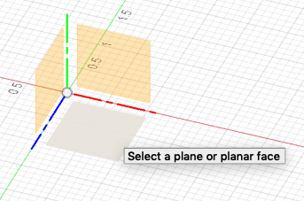
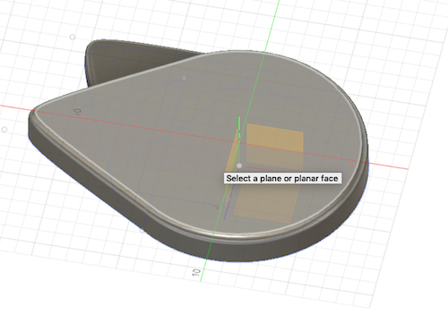
I made a sketch on top of the main body of the record player. When I was prompted to choose the plane on which I wanted the sketch to be on, I chose the top of body one. I created the new sketch and once again made the 12in and 15in diameter circles.
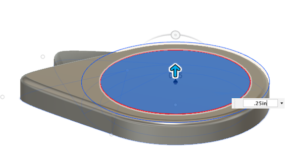
I wanted to designate the platform where the record would sit, so I extruded the 12in diameter circle up 0.25in. I’m not sure if this is how high the padding will sit underneath the record, but it’s an estimate for now.
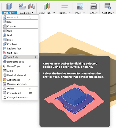
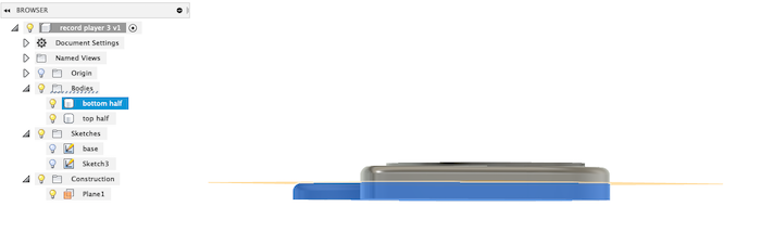
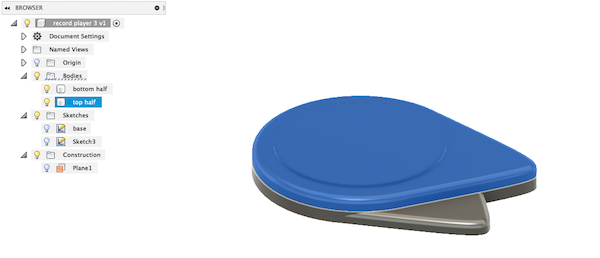
Then, I wanted to give myself the option of making the “add on” teardrop a different material of wood. So, I wanted to split the main body vertically, where the first inch from the bottom is one body and the inch above that is another body. To do this, I had to create a plane through the body and use the split body tool.
Splitting the body:
- Choose the plane from which the new plane will be offset. Choose the XZ plane.
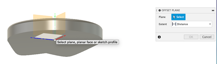
- Offset it by +1 inch. This will raise the new plane so that it cuts the body horizontally half way through.
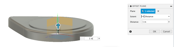
- Under the Modify section, choose Split body.
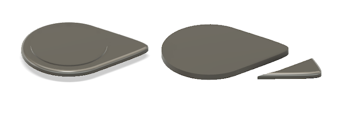
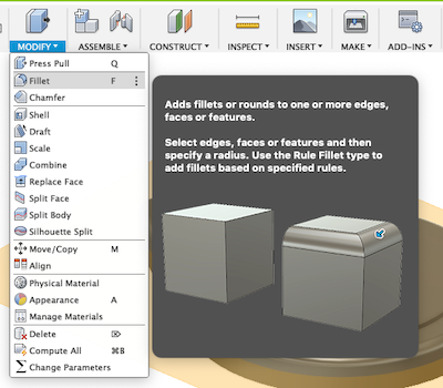
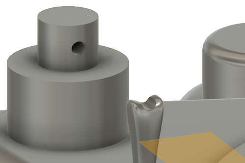
I wanted to fillet the edges of the bodies (round the corners), so I used the F keyboard shortcut.
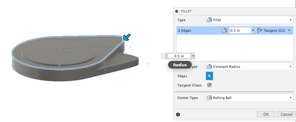
After selecting the edges that I wanted to curve, I specified that I wanted a 0.5 inch radius. I then filleted all of the edges.
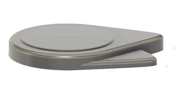
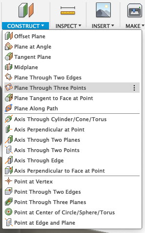
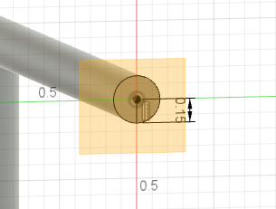
To represent the motor and tonearm, I just created various circles and extruded them upward. As of right now, I do not know how large the motor or tonearm components will be. In building the tonearm, I used various different types of construction tools, like planes. For example, on the end of my tonearm, I created an Offset plane with my offset being 0, so that I literally just created a plane where the face of the cylinder was. I also used Plane through 3 points at various instances.
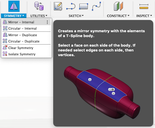
Modeling Environment
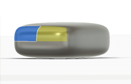
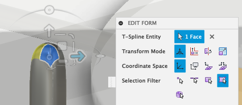
The Fusion 360 has an amazing Modeling environment, and this is where I created my needle and tonearm stand for the record player. In making both of these things, I used the symmetry tool a lot. I would select one face, edge, or point of the body, and then Fusion would show the symmetrical piece in yellow. Then, I could modify the figure and the other side would mirror what I had edited.
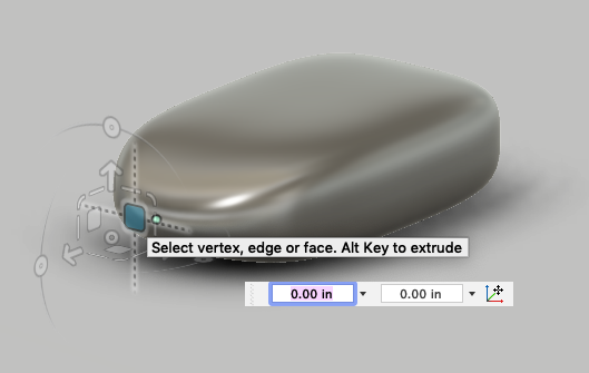
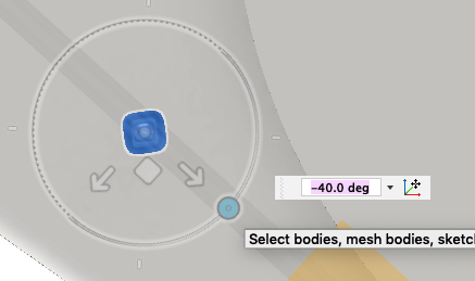
In creating the tonearm stand, I wanted to make something that looked fluid but not too rigid. So, I opted not to use the symmetry tool between either sides of the tonearm. This way, I can go back and really easily change how I want the tonearm stand to look. I did use symmetry between the two faces on the same side, but not between the two opposing sides of the tonearm stand. Since I created the tonearm at a 40 degree angle, I similarly had to rotate the tonearm stand so that the tonearm could easily bisect it.
Putting it all together
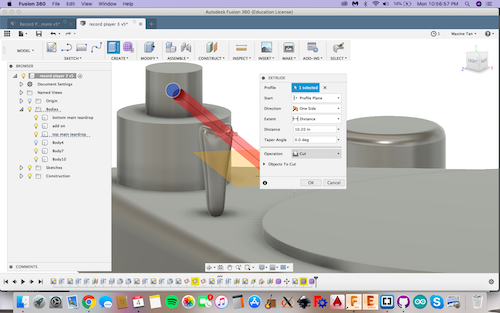
To ensure that the tonearm could sit on the tonearm stand perfectly, I cut through where the tonearm would be using the Extrude tool. First, I deleted my old tonearm. I then extruded in the same place with the cutting function of the Extrude tool. Then, I redid the tonearm, making it 9 inches long (the average length of a tonearm), again with Extrude.
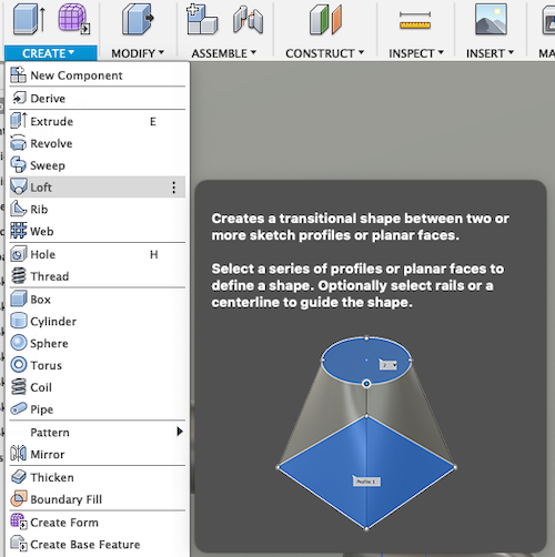
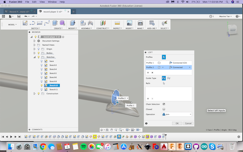
I wanted to smoothly connect the end of the tonearm with the needle. So, I created a plane right underneath the tonearm and created a sketch on that plane. I made a rectangle there, and then I extruded the rectangle up by a bit. Using the Loft tool, I connected the end of the tonearm and the extruded rectangle that I made. I first selected the rectangle and then the end of the tonearm. I tried to do it the other way (the end of the tonearm as face 1 and then the rectangle as face 2), but that gave me an error.
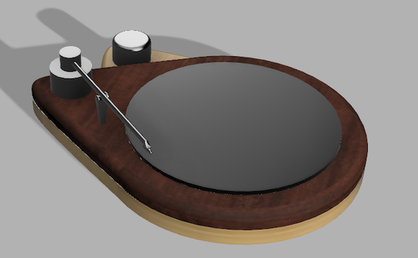
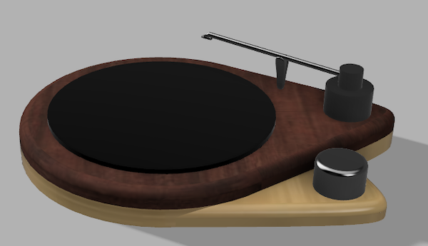
Finally, I edited how each face of the record player looked by simply accessing the Appearance function. I personally just use the A keyboard shortcut after selecting the face which I want to modify.
New Tonearm
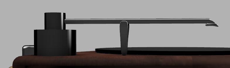
Dr. Fagan suggested that I get a tonearm off of GrabCAD since I myself will not design the needle and certain parts of the tonearm. So, I went to GrabCAD, registered, and downloaded this tonearm. GrabCAD is so cool! Obviously, oftentimes, I will be the one to design whatever I’m making on CAD, but this was a time-efficient way of showing a really nice tonearm in my CAD design.
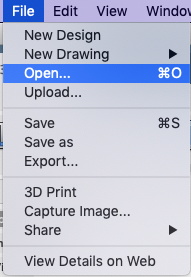
At first, I was confused because the file was a .stp, which isn’t Fusion 360’s format of .f3d. Eventually, I figured out that I can just go and Open the file underneath File. I learned that Fusion can really open a lot of different formats, not just its own .f3d.
After having the tonearm open in another document, I looked up how to take one body and move it into a different document. I learned from this Autodesk tutorial that you simply
1.Make the body a component
-
Select what you want to move (in my case, it was several components).

-
Press Command + C to copy the components.
-
Go to the other document, where you want to move the components to.
-
Right click and select Paste New.
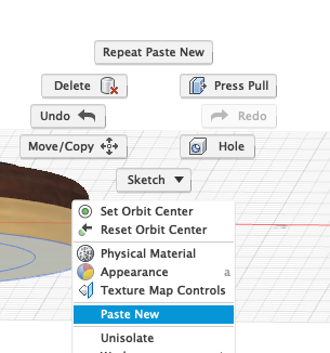
-
The new body should show up in the document.
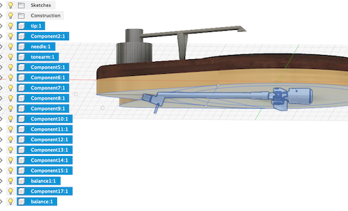
After putting the tonearm into the document with the record player, I simply moved the tonearm and rotated it with the M keyboard shortcut.
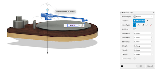
I positioned the new tonearm correctly, and I deleted the bodies of the old tonearm. This gave me error messages, as I created several things that were dependent on the bodies, like offset planes based off of the face of a cylinder. I don’t need the old tonearm anymore, so this isn’t a problem.

Download my Files . This includes my Fusion 360 design, Inkscape design, and the tonearm file.
FreeCAD
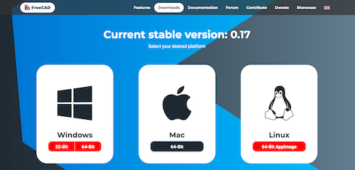
At the beginning of the week, I downloaded FreeCAD.
I played around with the boolean function, just as Neil talked about in the lecture. I added various shapes, including cubes, spheres, and cones.
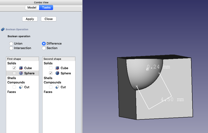
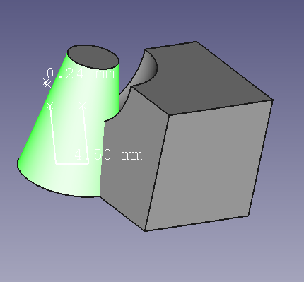
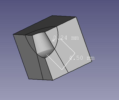
After I started using it, I determined that I really didn’t like it. It’s hard to determine distances and sizes for, especially since there’s no grid like Fusion 360 has. The objects just seem to be floating around randomly, with no relationship to real spaces and dimensions.
Summary
After using Fusion so much during the past school year and not using Inkscape, I forgot how much I hate Inkscape. Dimensions aren’t really clear at all, it’s hard to make a large variety of shapes, and the snap to grid function is, in general, just really annoying. Again, I already knew that I liked Fusion when I started this week, and this conviction remained true even at the end of this week. Also, I learned that I really hate FreeCAD. The lack of dimensions and sense of space is really bothersome and confusing.
I wouldn’t really change anything about my CAD rendering of my record player. Maybe, in the future, I’ll make changes to my design because of practical reasons (like I need a place to put my electronics, the two teardrop shape isn’t really feasible, etc), but I’ll worry about that when/if I get there.
I learned a lot about Inkscape this week, especially since I’ve never really delved too deeply into it. I learned the very basics about how to use Inkscape in my Engineering class in the past (we made tab boxes in Inkscape), but I haven’t done much else… Until this week.