11. Input devices
This week, I decided to create a board with a button input.
Eagle
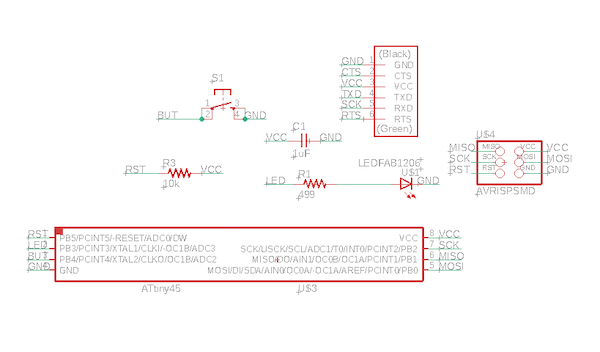
I designed a fairly simple board, taking example from the board I created in Week 7 (Hello World board) and the board on the Fab Academy page. I used an ATTiny45 because I did not need all of the pins that I would’ve had on the ATtiny44. I used every single pin on the 45, and I didn’t need any more than that.
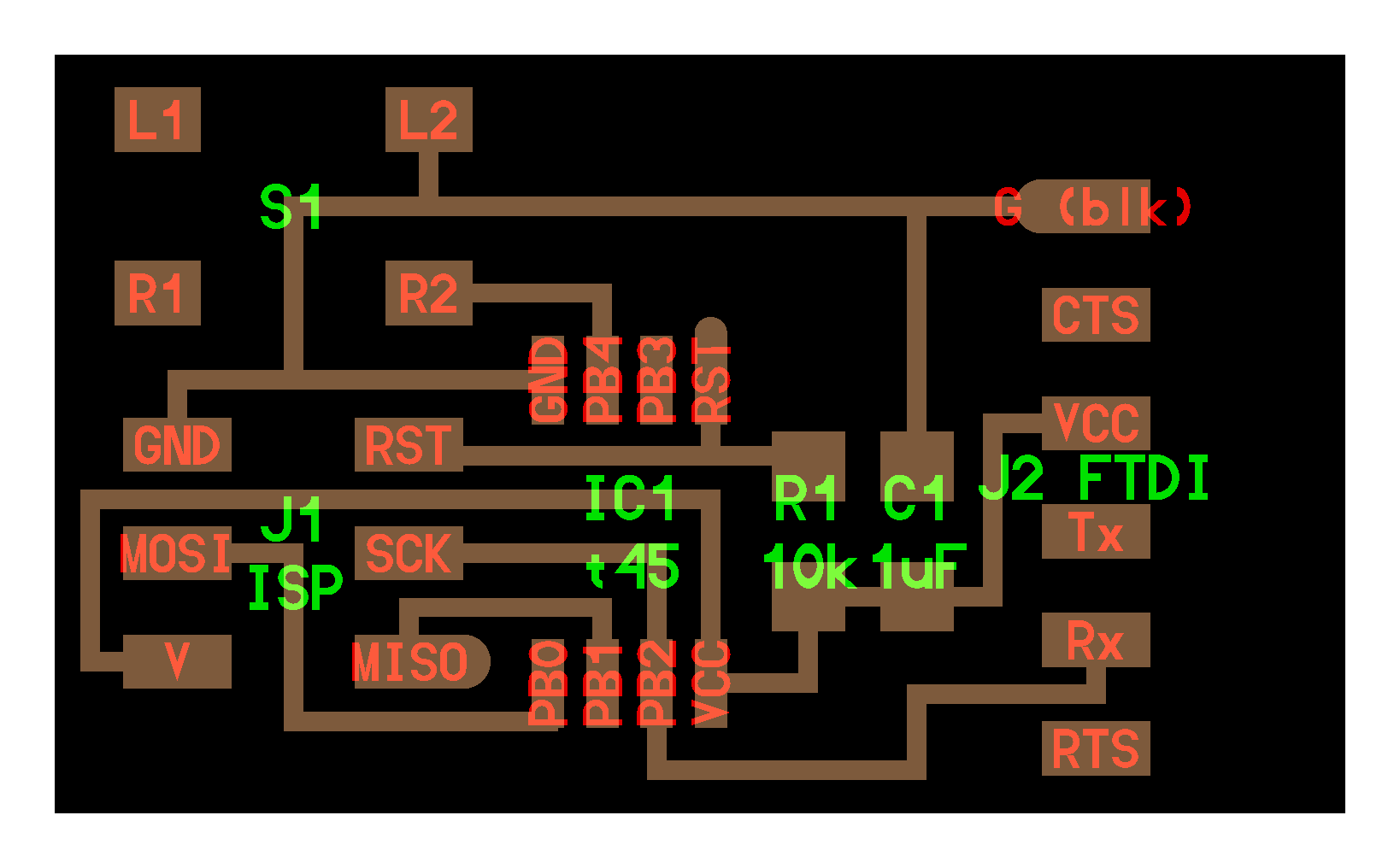
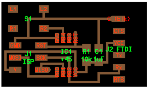
Neil’s board:
My schematic:
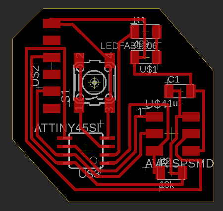
I created the board quite easily; when I autorouted, it automatically gave me a fully routed board. So, I didn’t have to edit it much and I just straightened out the connections (trying to make the connections horizontal or vertical) so that it would mill more quickly.
My board:
Download the board and schematic (.sch and .brd files)
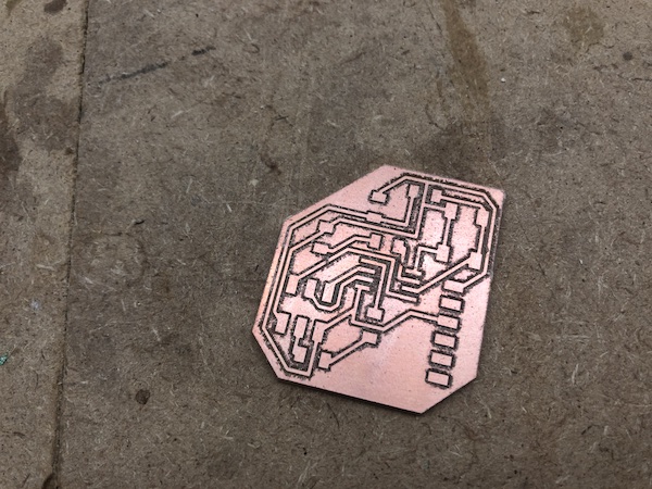
Milling and Soldering
Final milled board:
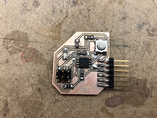
Final soldered board:
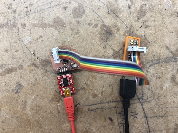
Programming
I lined up the grounds to wire the programmer to the board:
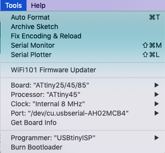
After opening Arduino, I went into Tools and changed the settings to the following, so that Arduino could communicate with the ATtiny45.
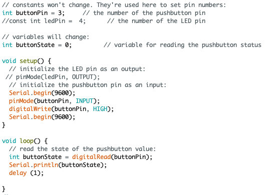
I tried to use Neil’s code with my board, but it did not work in making the button an input. The code would upload, but nothing happened when I pressed the button.
So, I tried writing my own code by utilizing the button example code in the Arduino example library:
However, Mr. Rudolph informed me that the ATtinys don’t use the serial communication that Arduino uses.
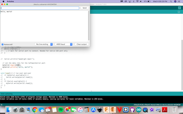
Dr. Harris suggested that I use the software serial example codes and work from there. First, to check that my hardware was functioning properly, I ran the software serial example code just by itself, unedited:
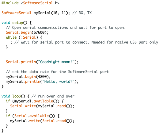
It uploaded and worked! It printed out “Hello, world?”
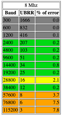
The ATtiny has an internal 8MHz processor, and I wasn’t sure what baud rate I was supposed to use with it. So, I found an AVR baud rate table that told me what baud rates are compatible with various processing speeds.
So, I edited the example button code to work with the example software serial code, and I commented what each line does. I’ve also described each line in more depth below.
Code / Explanation
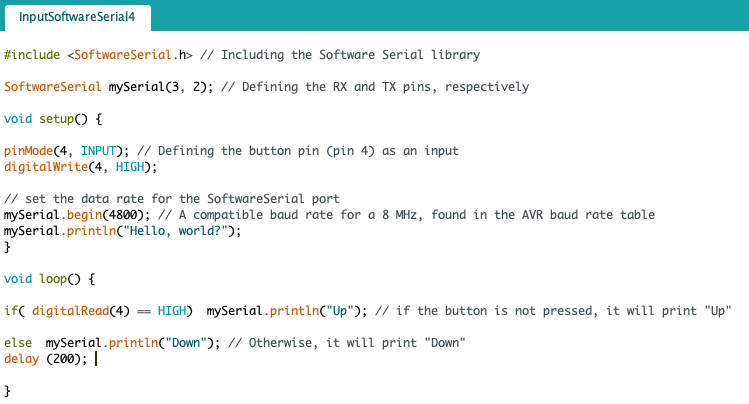
#include <SoftwareSerial.h> used the Software Serial Library since, again, the Arduino default “serial” is not compatible with ATtinys.
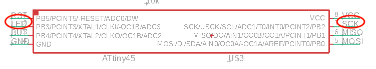
SoftwareSerial mySerial(3, 2); defined my TX and RX pins as (RX, TX). It also established a communication line called “mySerial.” mySerial takes the place of the function “Serial” that’s normally used in Arduino code.
These are my RX and TX pins:
pinMode(4, INPUT); defines pin 4 as an input. It’s where the ATtiny will be receiving the status of the pushbutton: whether it’s pressed or not.
digitalWrite(4, HIGH); uses the digitalWrite function on pin 4. Since I just defined pin 4 as an input in the above line of code, this line references the internal pullup resistor. I enabled the internal pullup resistor because I set it to high. Read more on the Arduino reference page.
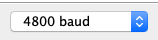
mySerial.begin(4800); defines my baud rate at 4800. As described above, 4800 baud is a compatible rate for a microcontroller running at 8 MHz.
mySerial.println("Hello, world?"); prints out “Hello, world?” in the Serial Monitor. This is to make sure that the ATtiny is able to communicate using Software Serial.
Within void(loop), I had an if statement.
if( digitalRead(4) == HIGH) mySerial.println("Up"); means that, if pin 4 is read as high (meaning that the button is NOT pressed), “Up” will print in the Serial Monitor. Again, this communication with the Serial Monitor is accomplished through Software Serial and the communication line “mySerial.”
else mySerial.println("Down"); means that, if pin 4 is read as low (meaning that the button IS pressed), “Down” will print in the Serial Monitor using Software Serial / mySerial.
delay(200); delays the whole void(loop) action 200 milliseconds. Once 200 milliseconds passes from the previous loop being completed, a new loop will start. This is how a stream of data is put into the Serial Monitor.
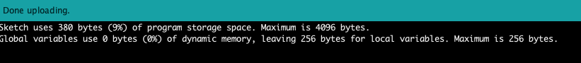
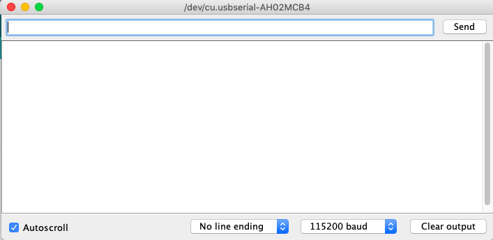
Then, I uploaded the code. I opened up the serial monitor and made sure that I set the baud rate to 4800 since I defined 4800 to be my baud rate in the code.
A video of the button working as an input:
Group assignment
We measured the inputs of both rotary and linear potentiometers this week. The assignment wanted us to “probe an input device’s analog levels and digital signals.” I didn’t really know what analog and digital meant; I sorta knew what they meant, but I looked at Sparkfun’s explanation to make sure that I fully understood the meanings of these words. I put the most important concepts in the following chart:
| Analog | Digital |
|---|---|
| Infinite possibilities | Discrete, finite number of possible values |
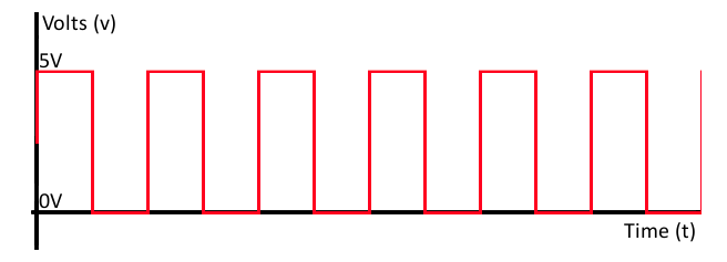
| May be limited to a range, but still an infinite number of values between the max/min | Oftentimes one of two values (like 5V or 0V) |
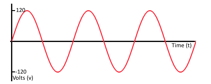
| Smooth and continuous graph | Square wave |
| Resistors, capacitors, diodes, transistors, op amps | Logic gates, microcontrollers |
An example of an analog signal (from the Sparkfun page):
An example of a digital signal (from the Sparkfun page):
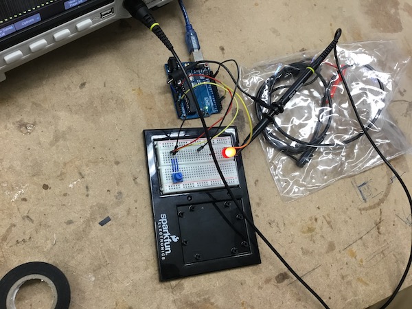
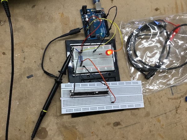
Here’s the setup of the rotary potentiometer:
Setup of the linear potentiometer:
Video of our analog signals:
Notice that, as we slid the potentiometer to all the way on/off, the light intensity changes. Simultaneously, the draw changed as well.
Then, we measured our digital signals. Will explains in the video that moving the potentiometer all the way on or off will be reflected in the oscilloscope; the level of the signal will be all the way at the bottom or all the way at the top. However, when the potentiometer is set to something other than the two extremes, the signal level rapidly jumps between the extremes.