Mechanical design
| Documentation |
|---|
| 1.LaserCutFiles.dxf |
| 2.3DPrintFiles.stl |
| 2.Fusion360Archive |
Context
The spooling system
Constraints
By observing the video above we can see few important caracteristics of the machine.
- We need to add a weight to the thread. This force on the thread is an important feature.
- We can see that the thread rotates along its axis as it goes down so we will need to counter this effect to not damage it.
I need to make a system with two degrees of freedom :
- One rotation along the shaft to spool the thread
- One rotation along the thread to avoid any damage

As we can see on the video, one rotation of the knitting machine is equal to one rotation of the thread.
I wanted to do it as much as possible using the tools available in the lab so I’ll use standard parts, 3D print the casing of those parts and laser cut the machine.
Spooling System Design
The design
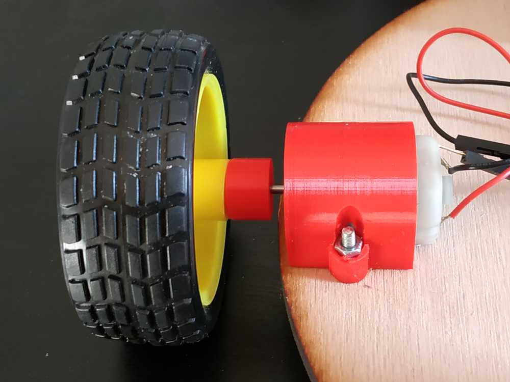
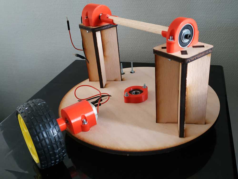
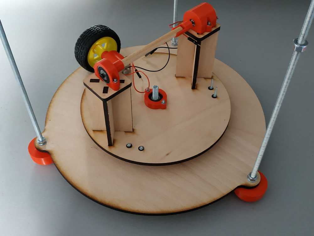
The idea this time is to use a motor to rotate a platform.
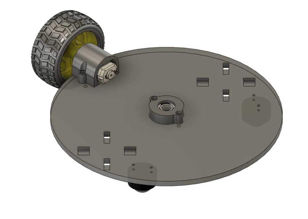
- A wheel linked to a motor will rotate the platform
- A shaft will be placed in the bearing in the middle of the platform in order to guide the rotation
- There are two freewheels to keep the platform level as it moves
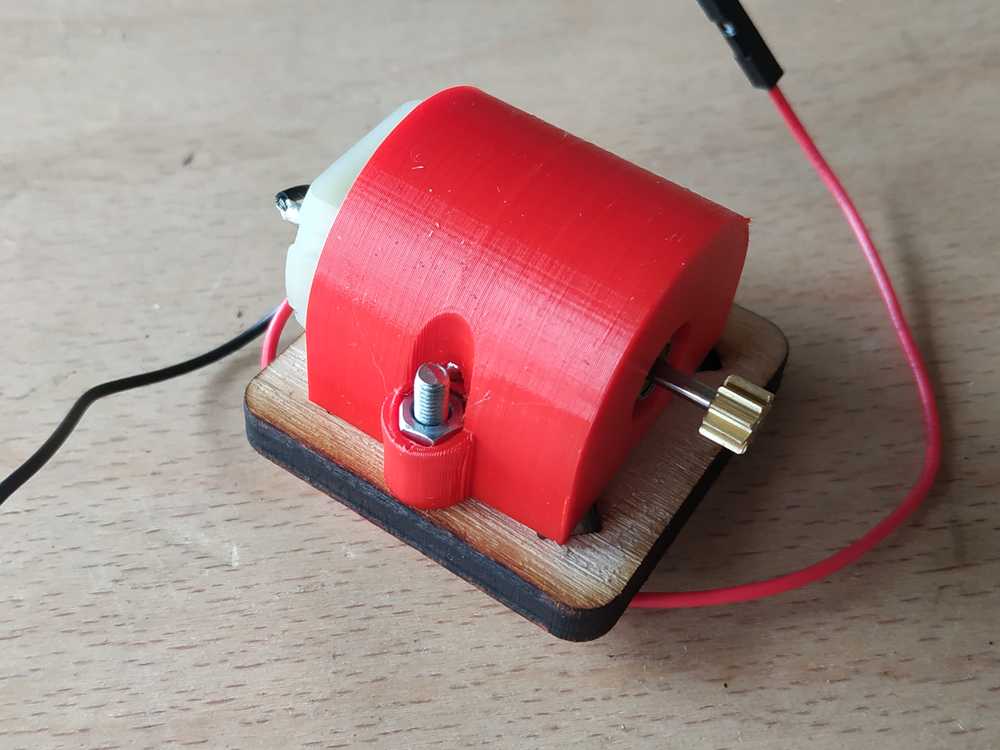
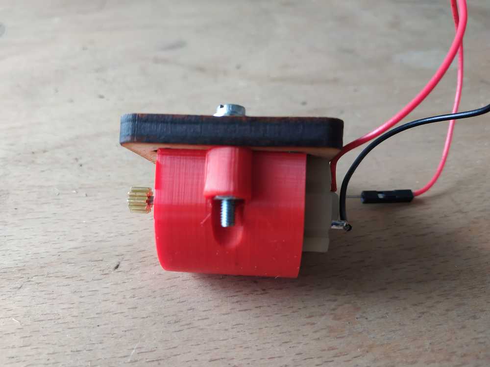
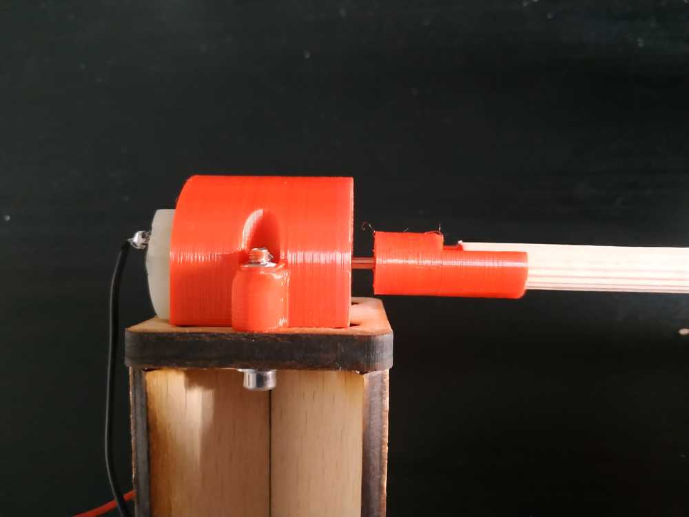
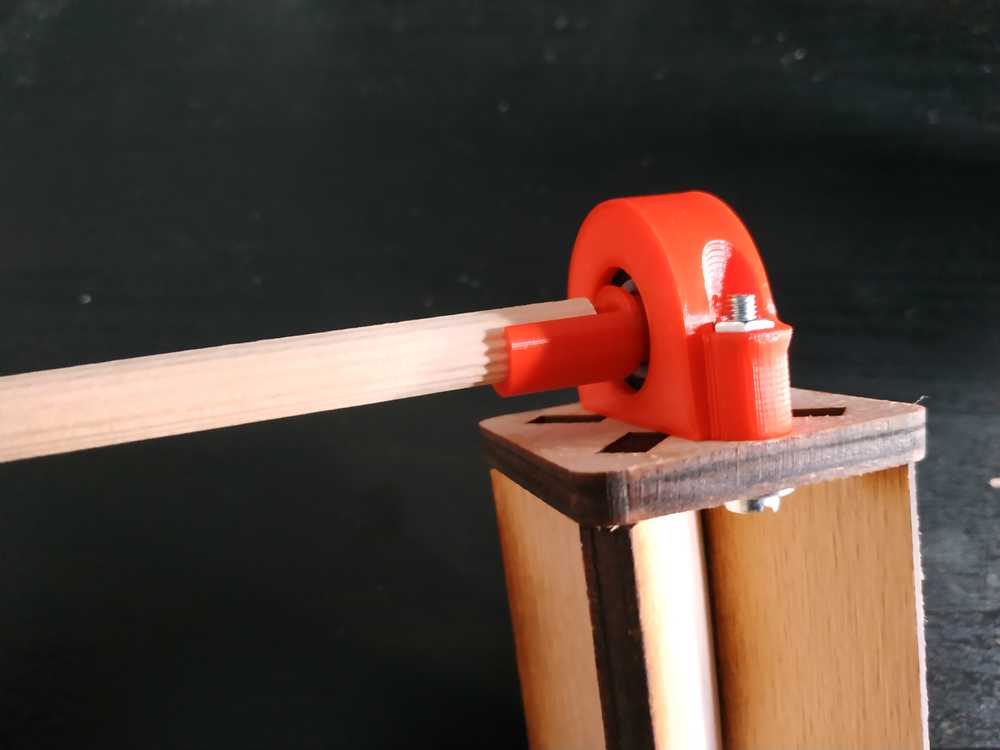
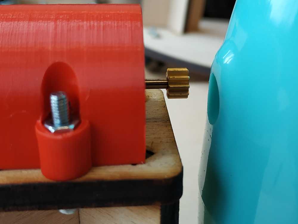
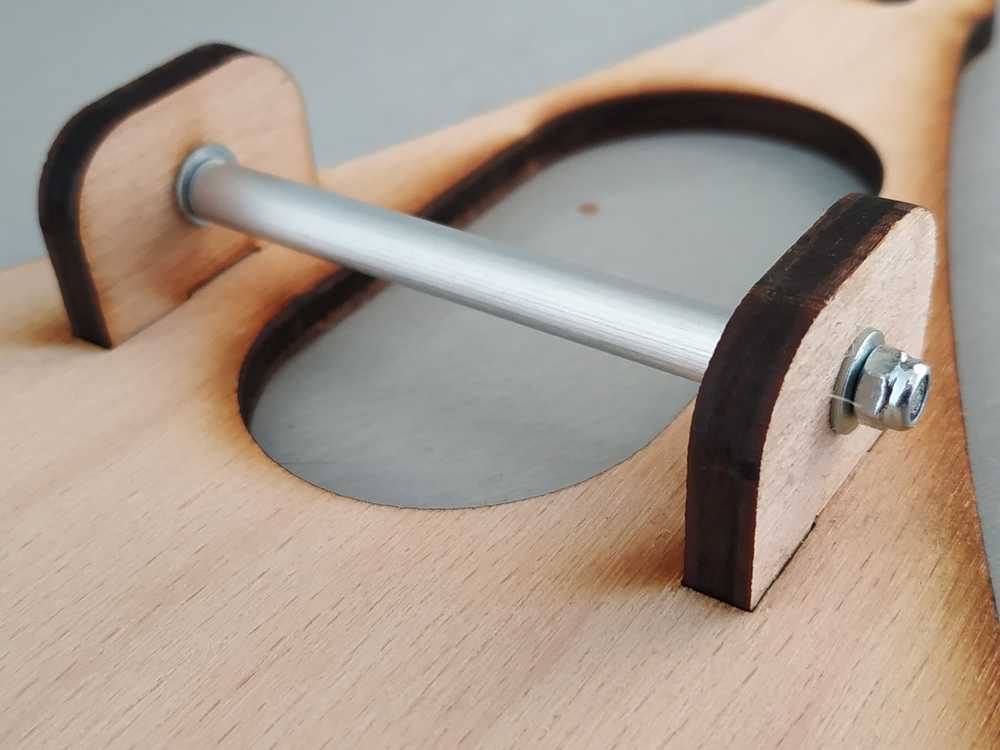
On the platfrom I added another motor for the shaft of the spool
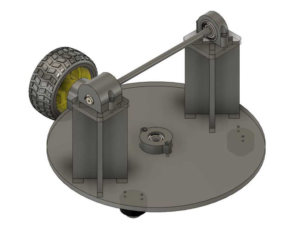
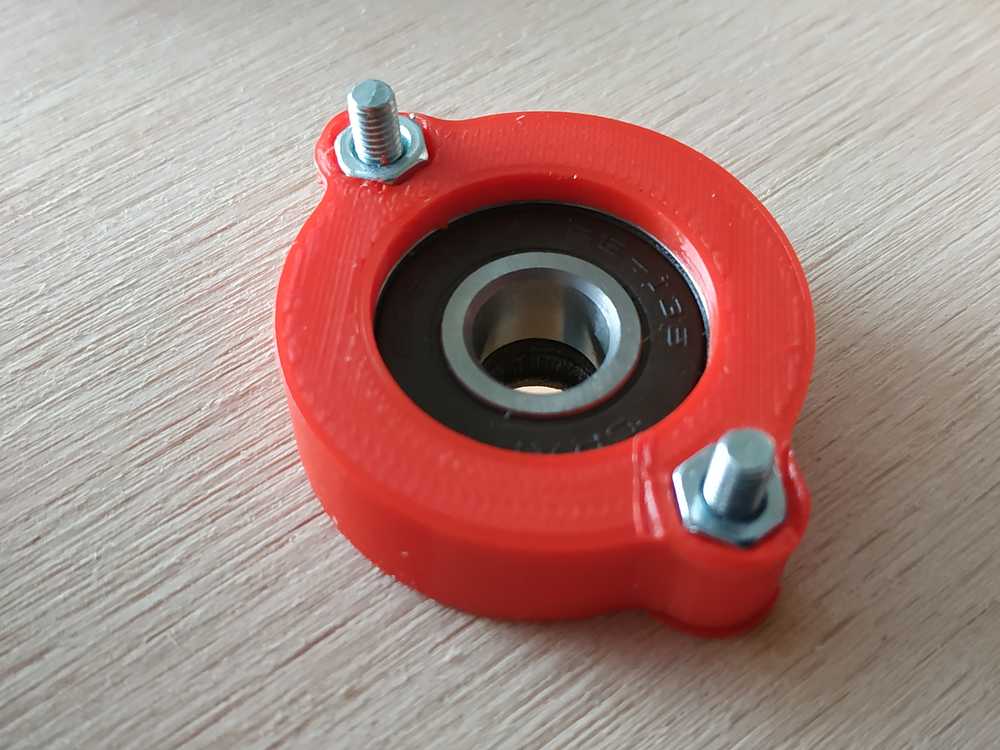
- A 3D printed part is connected to the motor
- A 3D printed part is connected to the bearing
- To place the shaft we just have to snap it into the 3D printed parts. This way we can easily remove it once it’s done.
Making the system
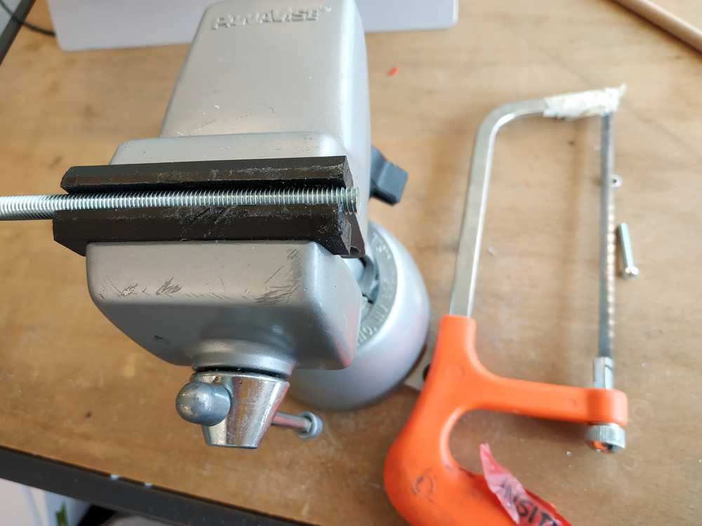
Equipement needed
To assemble the machine I need :
- To laser cut some parts
- To 3D print some parts
- Two 608zz bearing
- Two freewheels
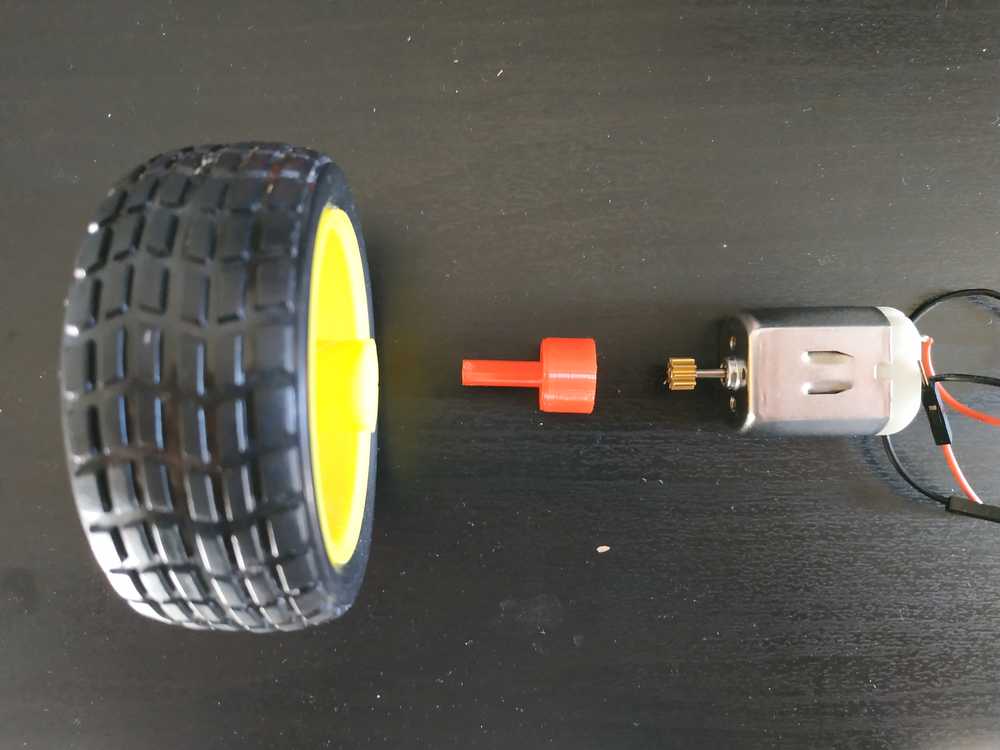
- One wheel
- two DC motors (from arduino starter kit)
- A 8mm wooden rod
- M3x20 bolts
- M3 washers
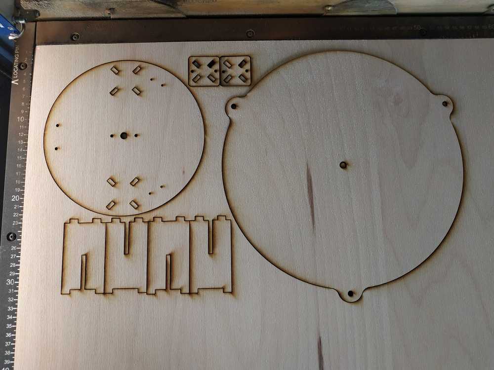
Preparing the parts
I’ve cut the platform usin g a 5mm thick plywood plank. I used the following parameter on the epilog fusion M2 :
- Speed 6
- Power 100
- Frequency 50
- Pass 1
I’ve printed the parts using an Pursa MK3 :
- Material PLA
- Infill 15%
- Brim ON
- Support ON
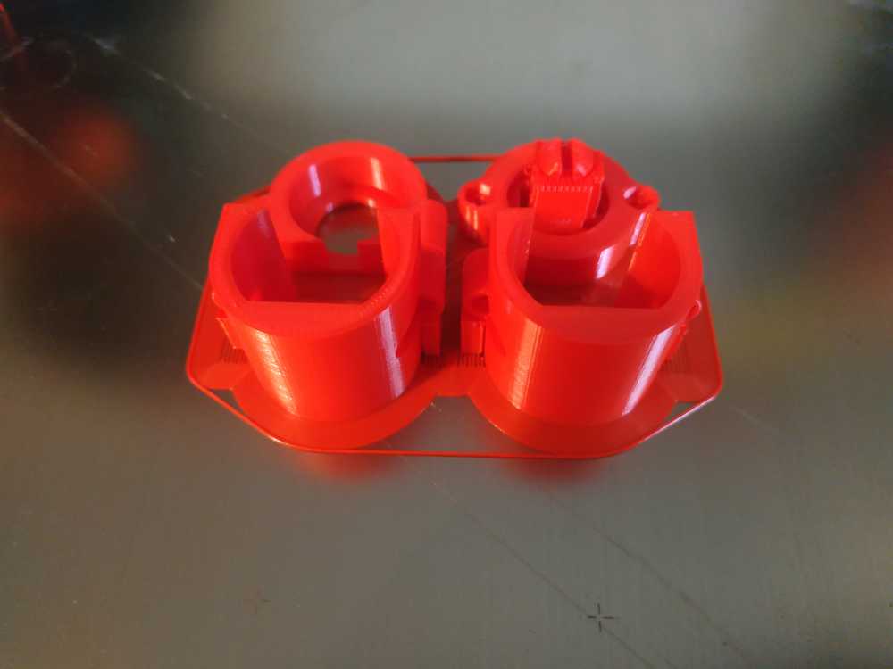
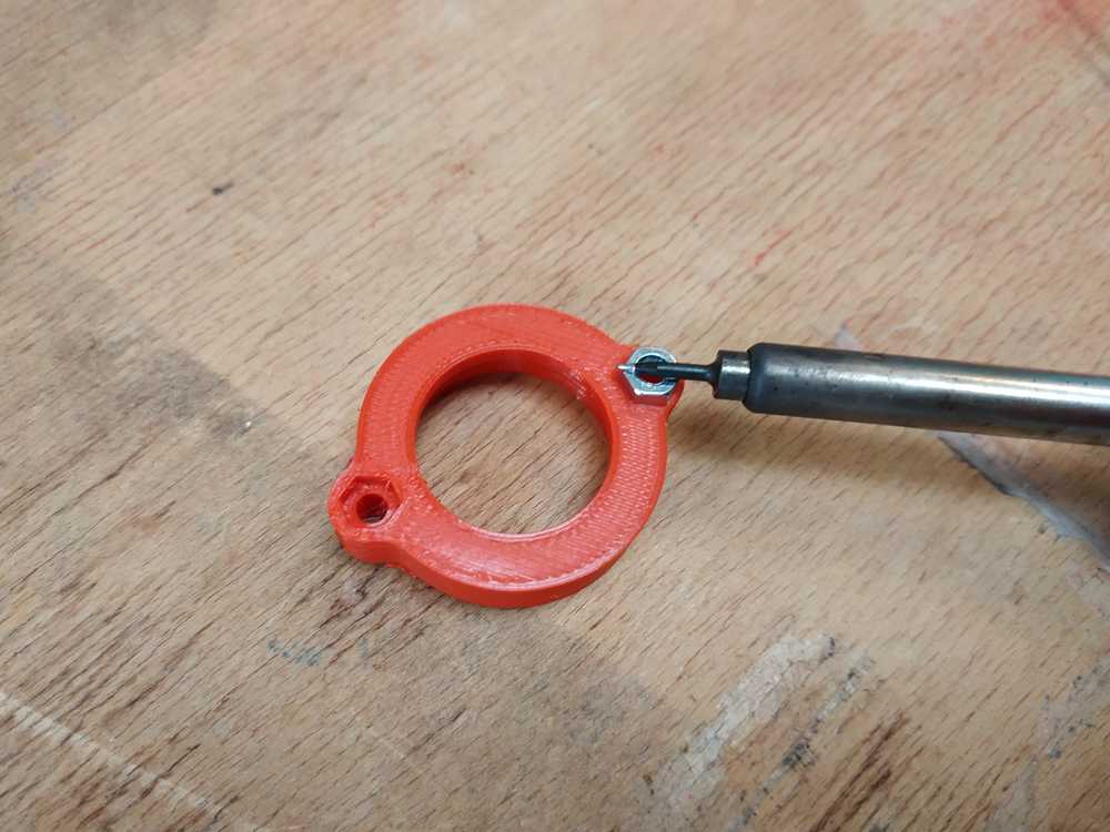
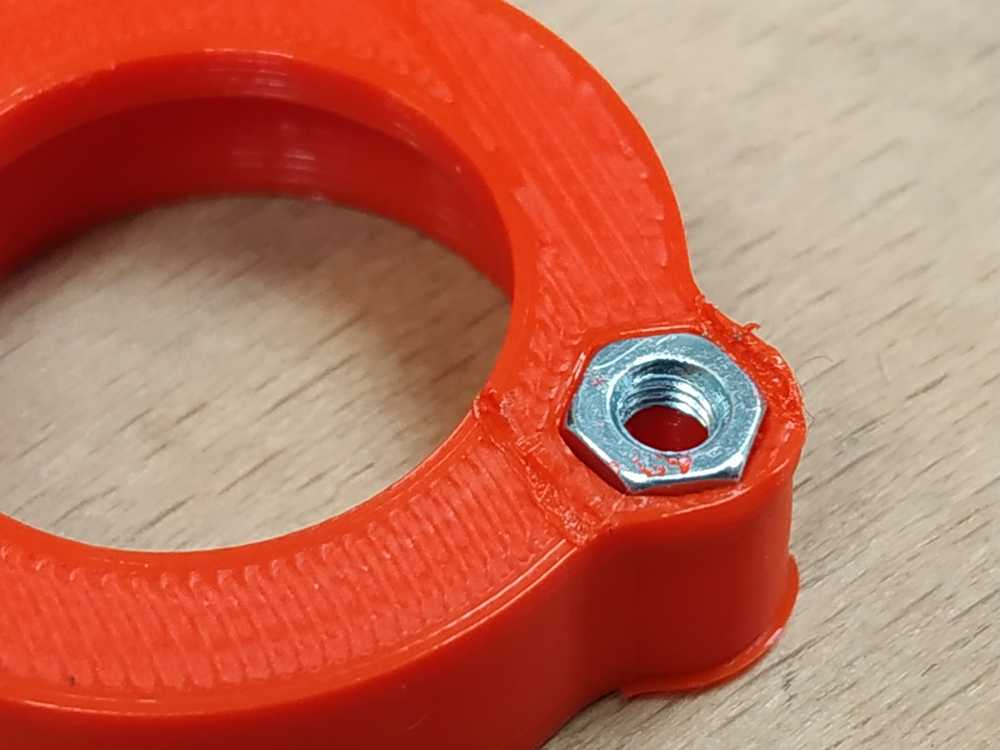
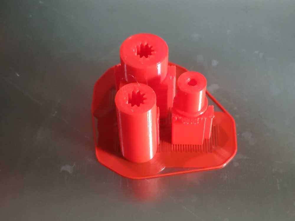
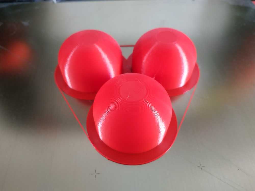
I’ve designed my cases with a footprint to fit a nut in it. To bond the metal part with my plastic part I heated the nut using a soldering iron.
 |
 |
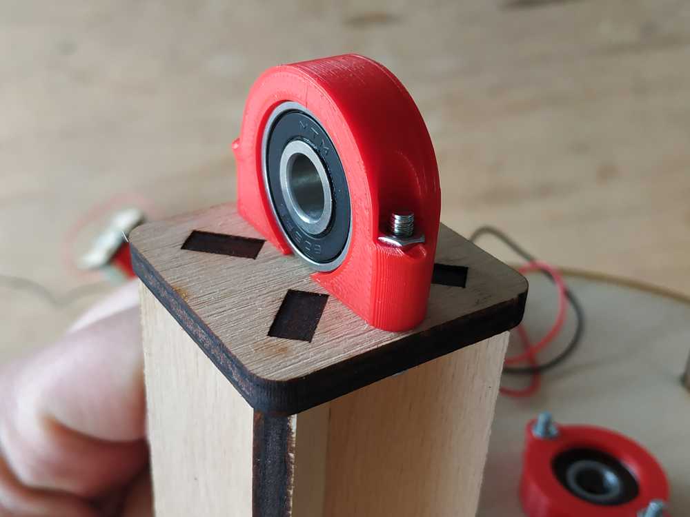
Then I assembled everything as shown below
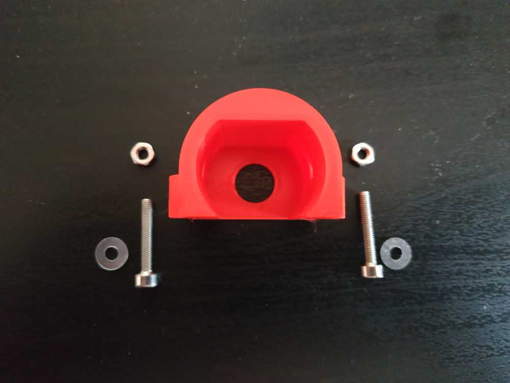
Here are some photos of the assembly
 |
 |
 |
 |
 |
 |
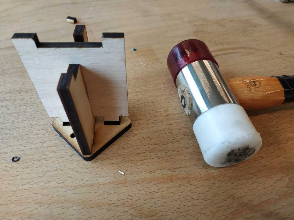
The wooden part are designed as a press fit kit. It’s a snug fit, I used a hammer to make it fit properly.
 |
 |
 |
 |
 |
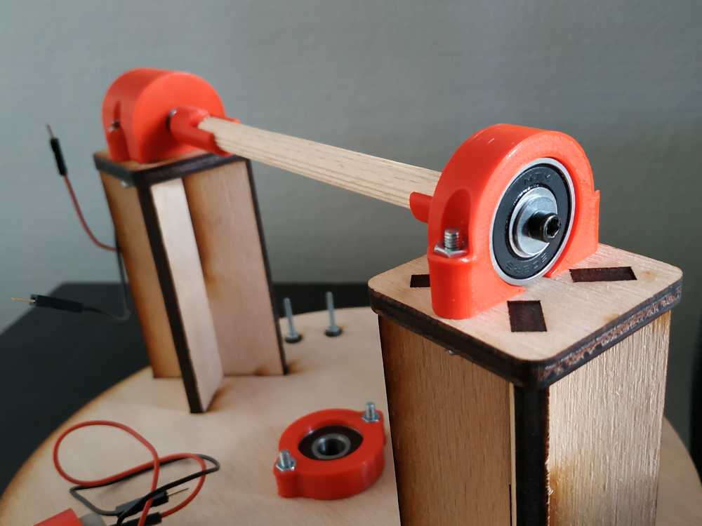 |
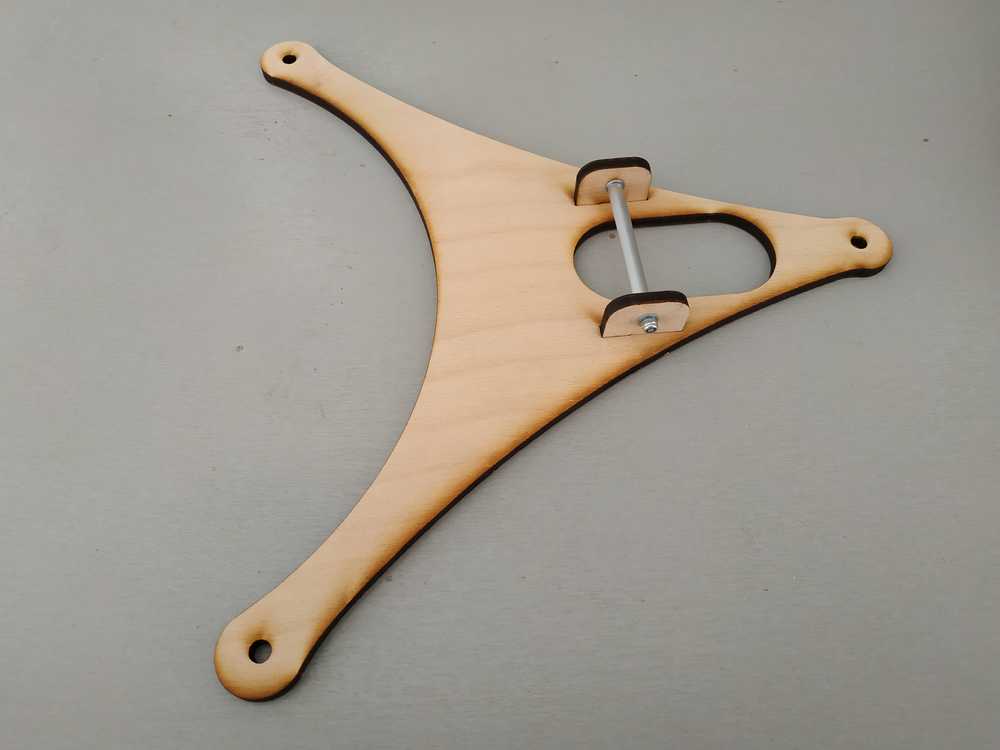
Here’s the whole platform assembled
Then I thought of the design of the whole machine to fit Camille’s part as well.
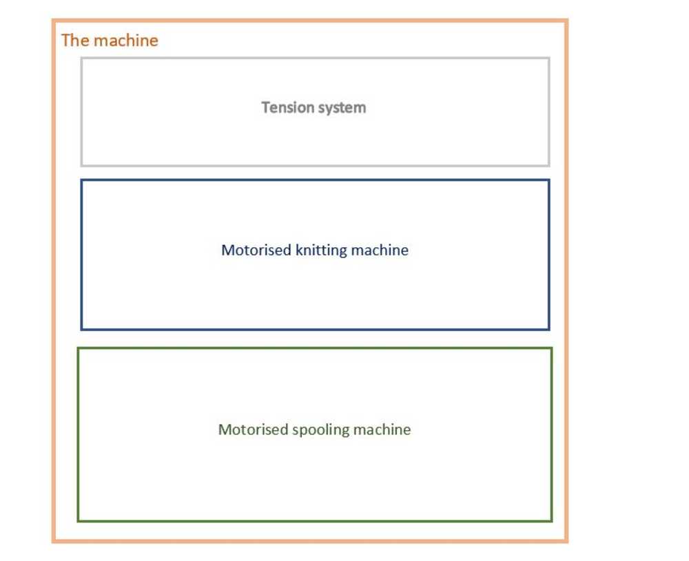
The machine
Concept
We wanted the machine to be modular with three levels. each level being connected to another one using 6mm threaded rods :
- Level 01 will be a platform with the spooling system on it
- Level 02 will be the knitting system
- Level 03 will be a level to give strengh to the overall machine and give tension as well on the thread
NOTE : For this machine the second level is an existing machine modified for our need but it could be a model made in a fablab. The fact that the levels are independent means it’s easy to change the knitting system for another one (with more needles for example).
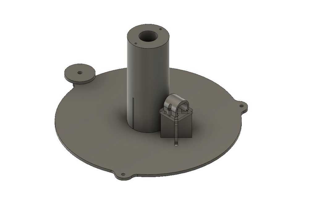
Level 01 : The holding platform
The level 01 is a very simple design. It’s a platform to hold the spooling system. It has a hole in the middle to connect to the bearing of the platform and it has three holes to hold the rods to connect the different levels on the sides.
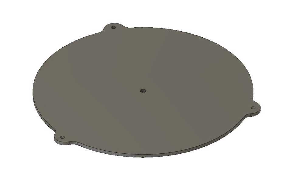
I cut the part in the lasercutter in 5mm plywood using the same parameters as before. Then I mounted the rods (I used 50mm long 6mm threaded rods) with nuts. I put a whasher on each side to protect the wood.
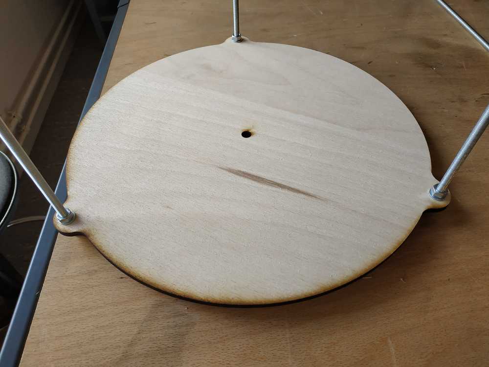
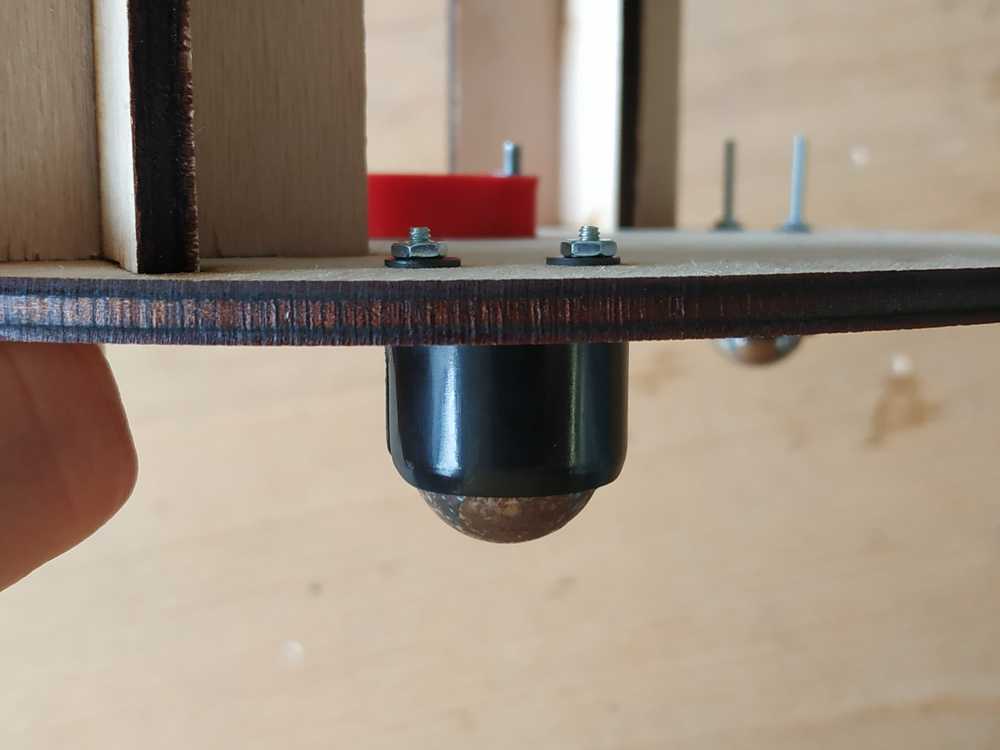
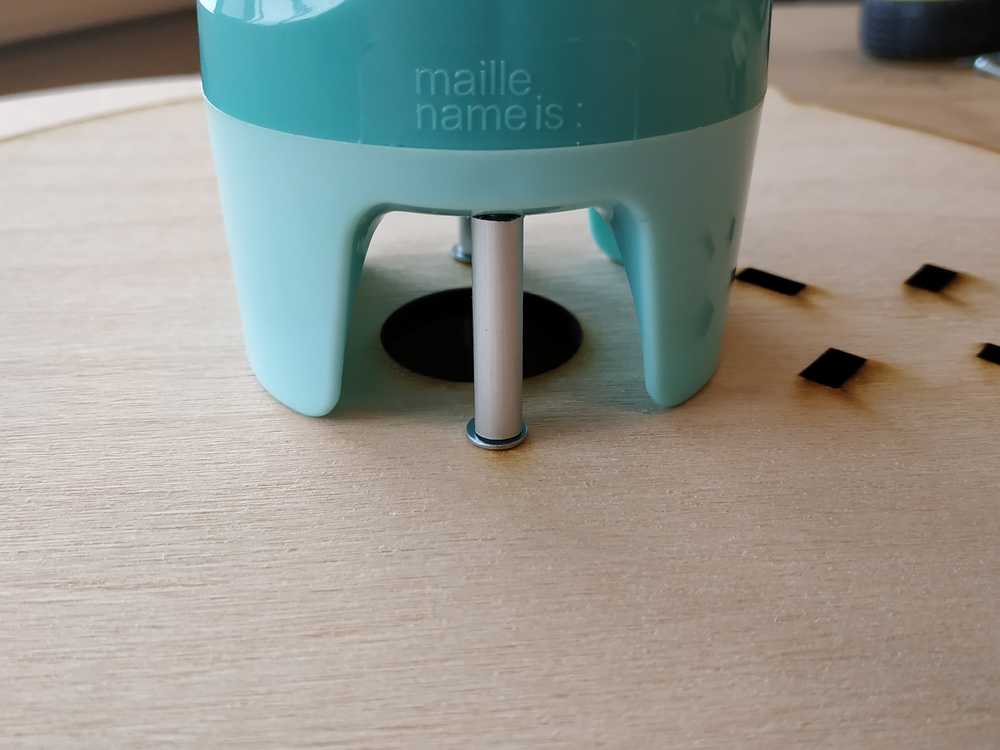
I’ve 3D printed some feet for the machine to be more stable
 |
 |
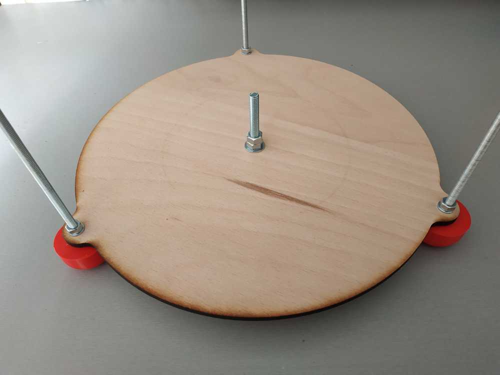
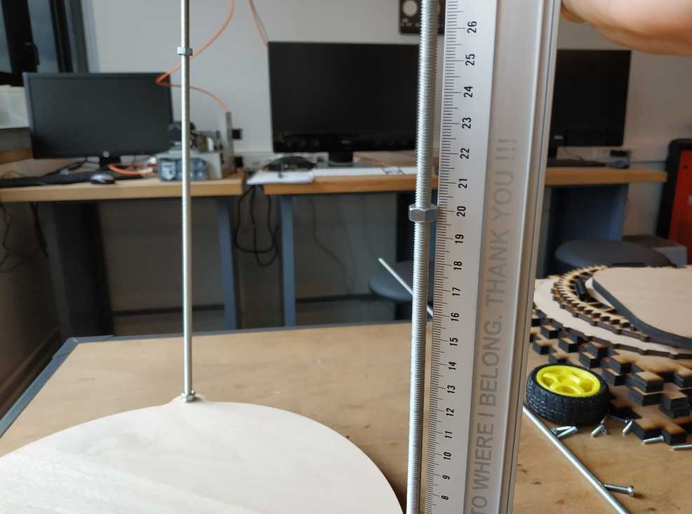
I then used a 60mm long 8mm bolt to connect the platform to the spooling system
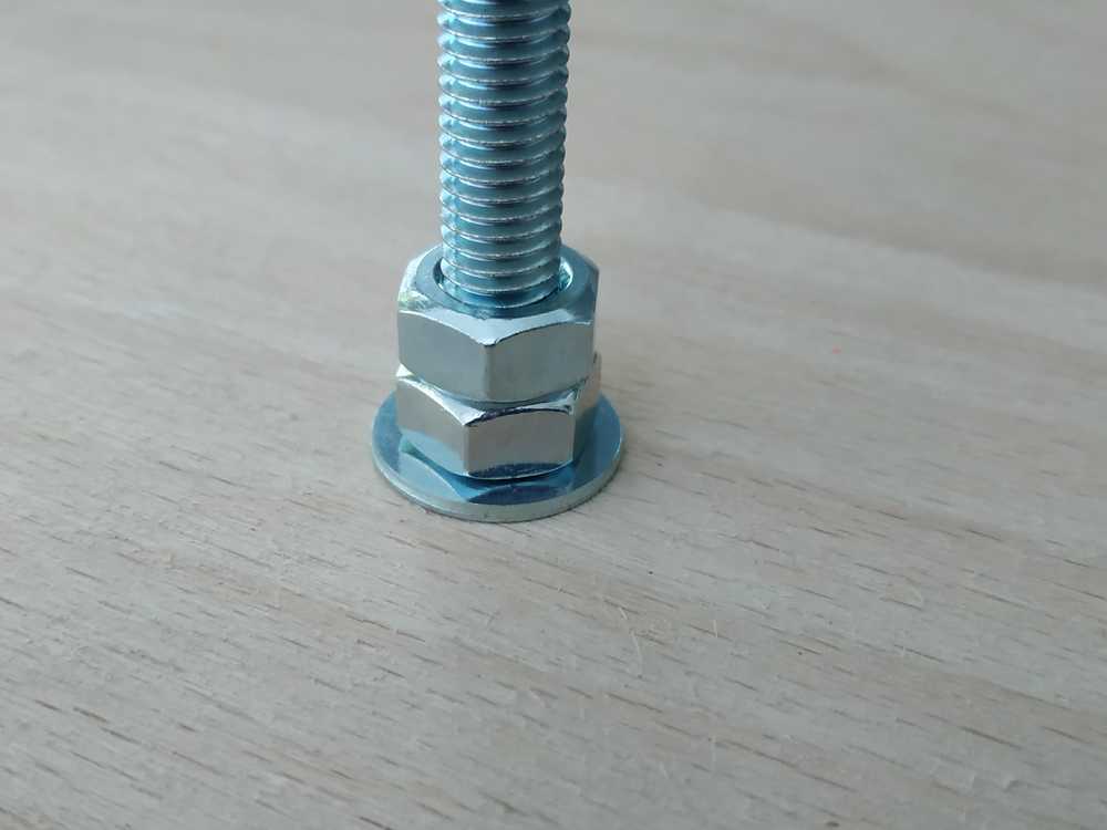 |
 |
Level 02 : The knitting system
On this platform we put :
- The kitting machine
- The motor to operate it
- A spool holder for the yarn
- Holes to connect to the rest of the machine
More information on the design :
- The knitting machine is screwed to the platform
- We will use the rods as guides for the yarn, we just designed a platform to hold the yarn
To assemble this level we need :
- To laser cut some Parts
- To 3D print some parts
- M3x20 bolts
- M3 washers
- M6 nuts
- M6 washers
- Two M3 threaded rods
- Two aluminium tubes
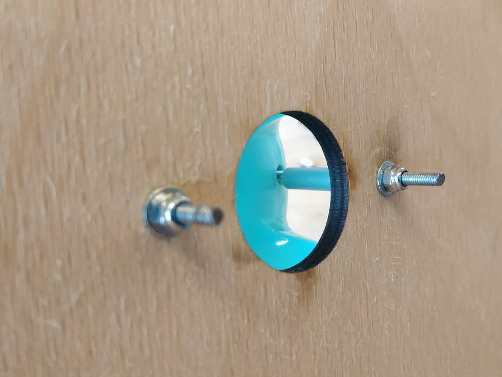
I have cut my 3mm rods and my aluminium tube
- 2 x 60mm for my threaded rods
- 2 x 40mm for my aluminium tubes
To screw the knitting machine, I removed to screws at the bottom of the machine and replaced it by the two rods. I placed the tube of aluminium around the rods.
 |
 |
The motor and its platfrom are the same design as before so the assembly is the same.
To assemble this level to the rest of the machine placed some nuts on the 6mm rods 200 mm above the previous level.
 |
 |
NOTE : I made a mistake taking the dimensions, my motor wasn’t in front of the machine, so I adjust the lenght of the platform of the motor.
Here’s a photo of the platform assembled.
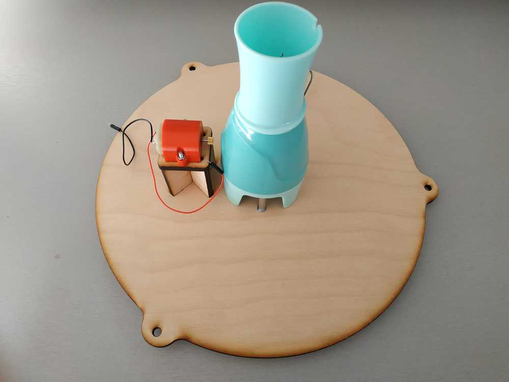
Here’s a photo of the platform mounted.
Level 03 : The tension system
The purpose of this level is to :
- Give strenght to the whole machine
- Give tension to the yarn before it goes to the machine

NOTE : Here again the fact that the hight of the platform can be adjusted is good because it means we can have big or small yarn, we can adjust the hight of the level.
Here again a simple design, we will need to assemble this level :
- To laser cut some Parts
- To 3D print some parts
- M6 nuts
- M6 washers
- M3 threaded rod
- Aluminium tubes
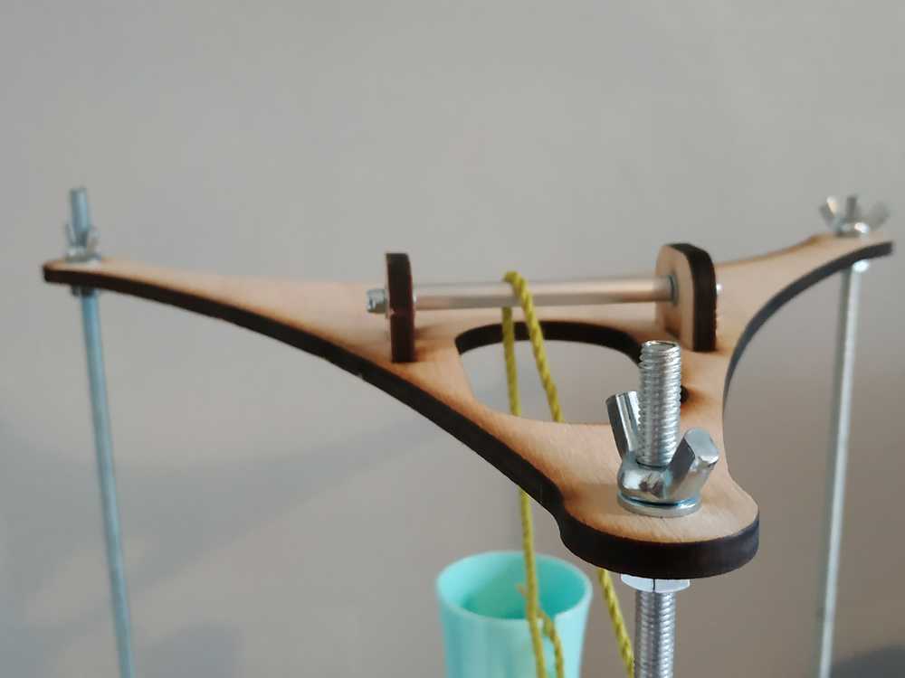
Here again I cut my M3 rod about 85 mm and my aluminium tube about 58mm, I’ve laser cut the different parts and assembled everything.
 |
 |
I then mounted the platform on the rods using nuts and washers
Final assembly and tests
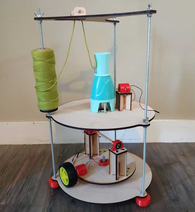
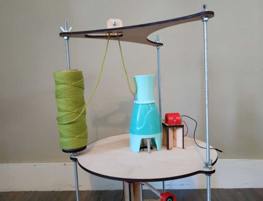
Here are photos of the whole machine assembled.
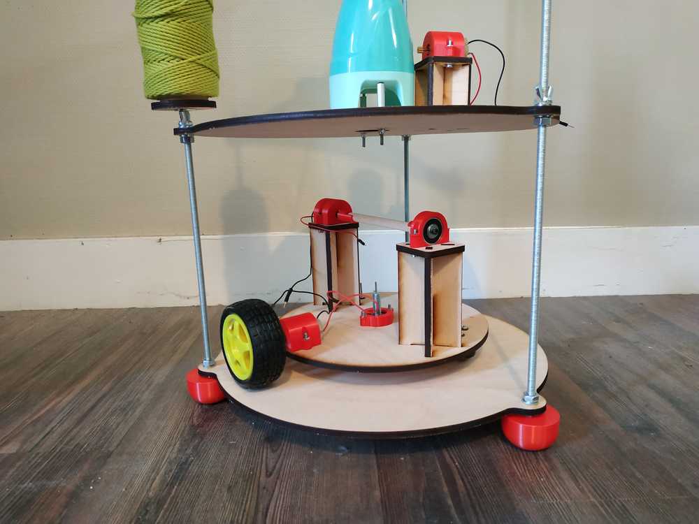 |
|
|
To test the spooling system, I’ve plugged a 9V battery to the motor connected to the wheel.
NOTE : At full speed we can see some vibrations but everything stand fine. We will need to control the speed of the platform to get less vibrations.
At this point everything seems fine, we are ready to go further.