CapStone project - FabLab Buddy
Motivation
As a member of the community, I want to contribute to build an ecosystem that will be viable from an economic point of view.
Fab Labs are struggling with money to remain accessible at low cost, ideally at no cost, to everybody. Fab Lab equipment are quite expensive, not only as a CAPEX but also when in operation.
It sounds fair to me to require members some kind of contribution when they use the equipment extensively. The issue is the following: Fab Lab cannot afford permanent staff that would control access, meter equipment usage, prepare bills and manage financial transactions manually.
My idea is to provide Fab Labs a device that could be installed in all locations where the Fab Lab manager wants to control access, perform automatic metering, ...
In this second video, I intentionnaly removed the top cover to show the interactions with the electronics
The journey and .. the result
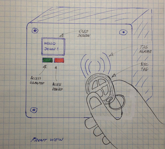
Here is the starting point: just a drawing showing how the final product would look like and how the interaction with the user would be...
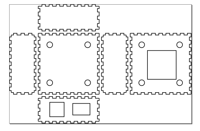
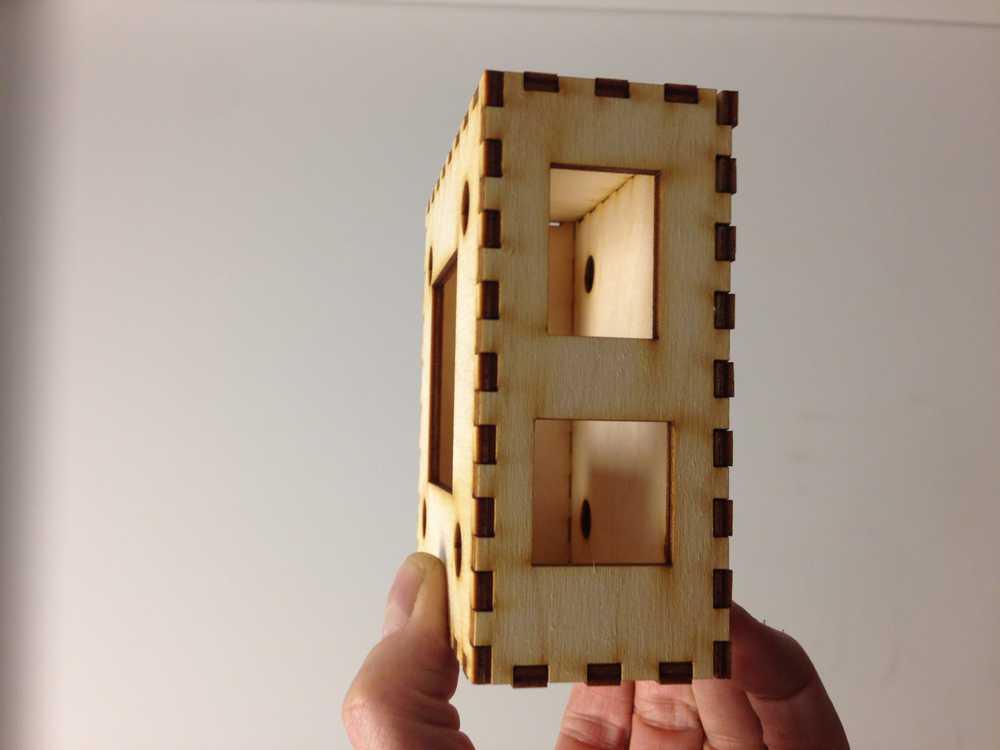
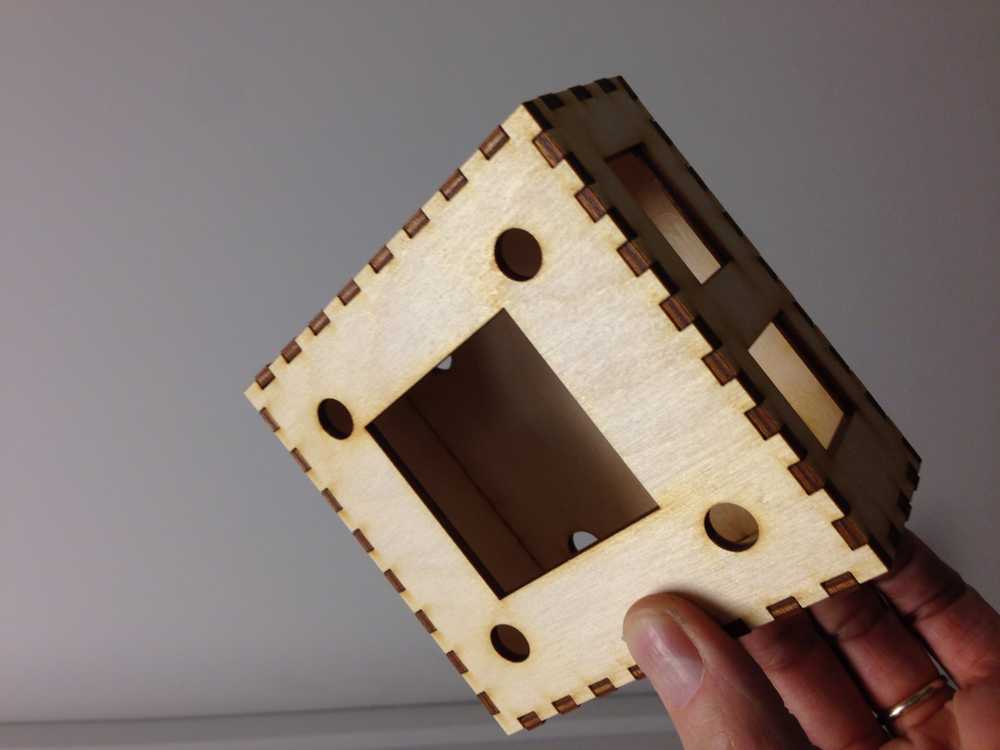
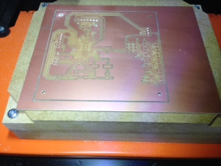
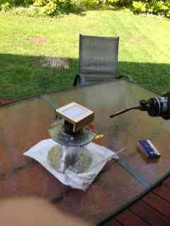
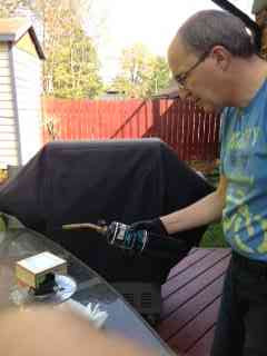
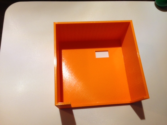
I started by making a first enclosure where the AC part of the circuitery will fit (note: the pictures show one of the prototypes, not the final one. I tuned it over the time but I forgot to take pictures
I struggled with a molded part for the top cover (at the end, I will not use it)
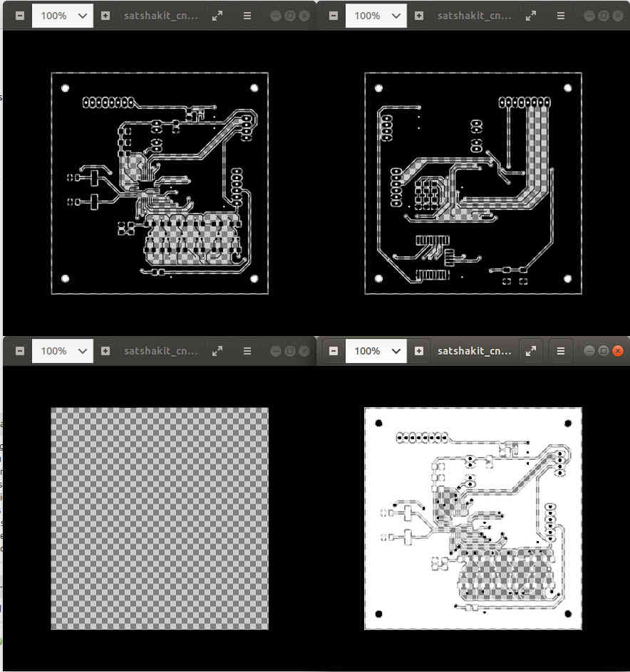
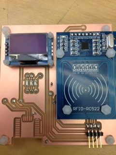
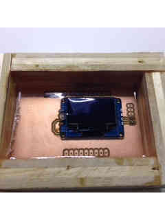
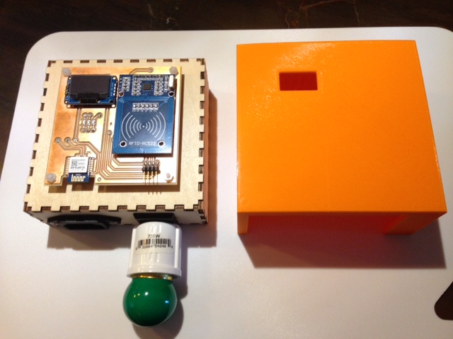
I designed a double face PCB, with an OLED, a BLE interface and a RFID reader on the front and the MCU on the back (along with the connectors, regulator and level shifters)
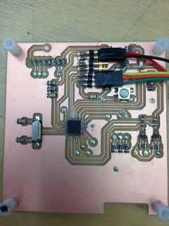
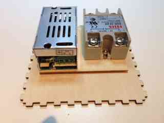
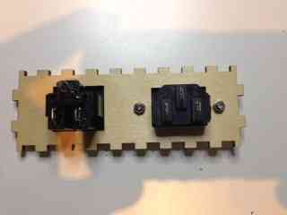
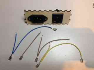
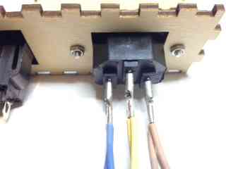
This is the integration part. To start, I fix the AC/DC and the SSR on the bottom face. Then I install the two outlets (AC in and AC out). I prepare the AC wiring and I connect it to the outlets. Note there are four DC wires in the back: two for the supply and two to control the SSR
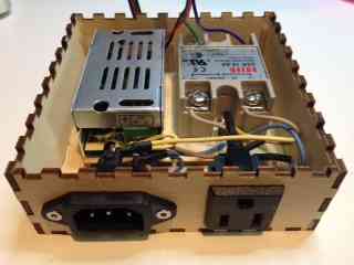
The PCB is initialy flashed with a bootloader through the ISP connector (front face, at the bottom right). Then I can upload my code over FTDI (the connector is on the back... no a great idea.. I know)
Here is the final result, with the pcb fixed on the top of the internal enclosure

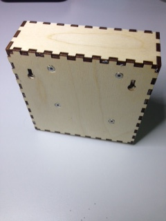
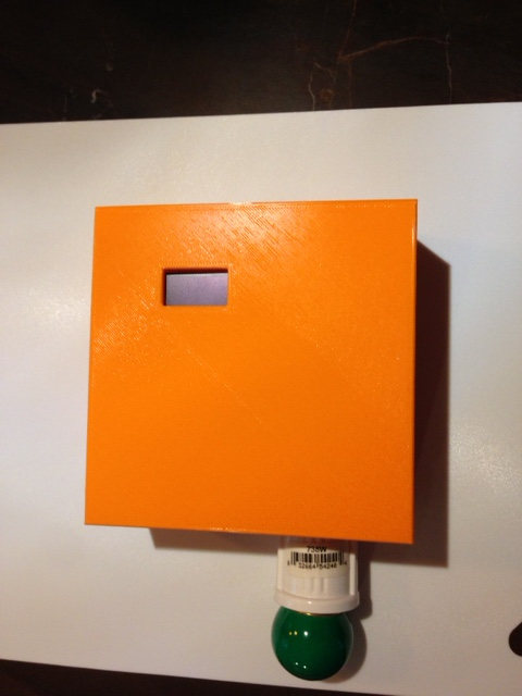
The last step is to install the cover
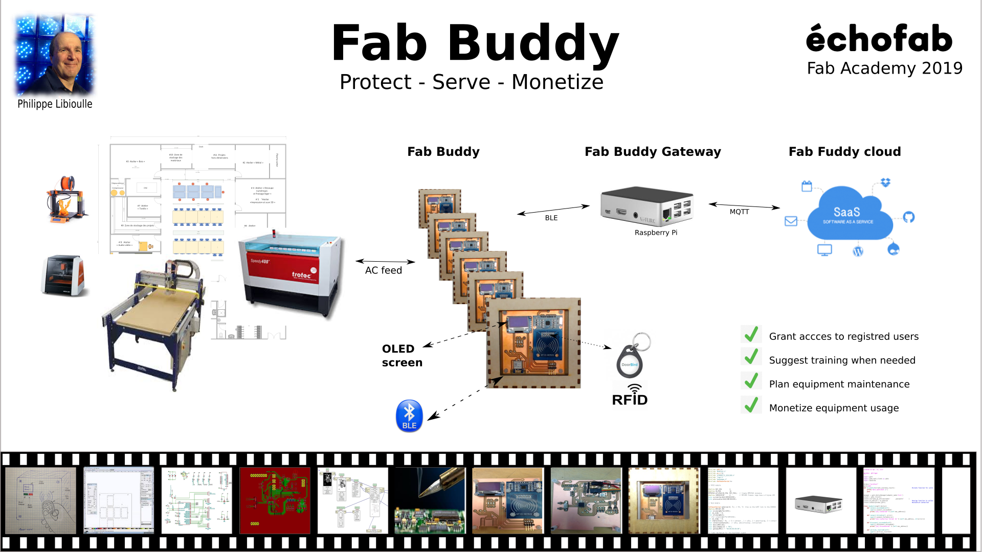
System and product overview
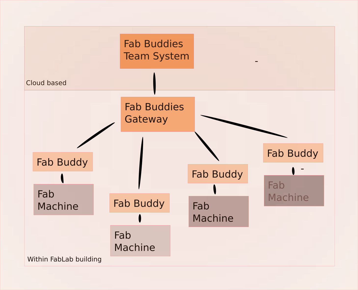
My idea is to provide a system that could be installed in a Fab Lab, with devices in all locations where the Fab Lab manager wants to control access, perform automatic metering,... There are three parts: the Fab Buddies, the Fab Buddies Gateway and the management system.
The Fab Buddy
Fab Buddies are installed within the Fab Lab where access control and/or metering is required. For example, a Fab Buddy is installed on the main entrance, to ensure that access will be granted only to registred members during some periods and to anybody during other periods. Another Fb Buddy is installed next to the big CNC, to limit access to people having the proper skills and having passed the security training. Another Fab Buddy is installed next to a 3D printer, to meter equipement usage.
The Fab Lab Buddies Gateway
Fab Buddies communicate with the gateway using BLE (Bluetooth Low Energy). The gateway is a small computer( like a Raspberry PI) that is part of the BLE network on one side and connected over a wired or a wireless link to the Fab Lab network and then to the Internet. The gateway runs a MQTT client.
The management system
The management system is cloud-based. The system handles multiple FabLabs. It offers a web portal (for members and for Fab Lab manager) and an API for future integration. Information is stored in a database.
What has been done beforehand ?"
FabMan
I was a little bit disappointed when I discovered FabMan but at least it made it clear my market anylysis was not wrong. If someone made a business out of it, it means there are customers and there is a need.
Here is what FabMan bridge does and fits with my analysis
- Act as a remote switch between a Fab Lab machine and the AC feed
- Communicates with a central system over an IP based network
- Support NFC-A, B and F tags, a along with ISO 15693 tags
- A lot of features related to membership management, like billing and tracking trained users (out of scope for my Fab Academy capstone project)
Here is what FabMan does but does not fit with my analysis
- WiFi connectivity: I took a different approach. WiFi on-boarding could be a painfull procedure and mixing end user wireless traffic with machine related traffic could be an issue from security point of view.
- Sensing activity, based on machine power consumption: great idea. My initial tought was that a machine is either busy or free but there is a third state, i.e idle. Collecting that information helps to prevent unattended operations and to turn off equipment when unused.
- A second relay: not clear what it is used for...
- The AC feeding the board looks connected to another plug. I don't know why and it sounds logic to me to use the same AC input to feed the pcb and to feed the load.
- A set of low voltage inputs and outputs. Great ! (as far as the management system knows what to do with the information)
- Support accesories like an exhaust controller, to prevent fire when the exhaust filter becomes full or is broken. Great idea !
- Using RJ-12 and RJ-45 standard connectors. I think it is no a great idea because, sooner or later, someone will connect a LAN device or a land phone on it and I don't know what will be the consequences.
- Allow members to use their smartphone instead of a tag. They did it with a trick. The smartphone is not detected, they use a QR code instead and (probably) a custom app deployed on the phone (or a subset of their web portal)
Here is what I plan to do and FabMan does not offer currently
- Use Bluetooth MESH to communicate between devices. Not sure I will get through it because it requires a custom load on the BLE module but it opens the possibility to let the devices talk together, reduce the dependency on the WiFi network and (in theory) reduce the cost of the product
- Use standard AC plugs. As far as I am using computer standard plugs, it fits everywhere in the world but it cannot handle large loads (over 15 amps)
Project scope and timeline
What is included
My FabAcademy deliverable is the Fab Buddy itself and a Fab Buddies Gateway that will be deployed on a Raspberry Pi with basic configuration and a MQTT server.
My target is to keep it as simple as possible, at the lowest cost possible. It could be easier to power my device with a big CPU but it is also expensive. The minimum requirements to have a viable product are:
- Read NFC cards operating at 13.56 MHz.
- Display instructions to end user on a small screen.
- Request user attention when needed, using a small buzzer.
- Control an external equipment (it could be a machine, a door, ..) through a 10A 110V AC relay
- Communicate over BLE with the gateway.
- Gets its own power from a standard AC outlet
What is NOT included
The Cloud based management system will be designed later, along with member entitlement and a lot of fancy GUIs.
BLE MESH: it looks really interesting (increased security, better range since the messages can hop over multiple devices to reach the gateway. It could work on my Bluetooth module (based on Nordic nRF52832 but requires an updated firmware that I cannot code in the project timeframe.
Who will do what and when
The what is clear, the who sounds obvious since I'm the only team member but the when has to be clarified. Here is the plan:
- Week 1 - plan and sketch a potential final project - DONE
- Week 2 - setup web site and this landing page - DONE
- Week 3 - learning - DONE
- Week 4 - laser cut a draft of the product enclosure (wood) - DONE
- Week 5 - learning - DONE
- Week 6 - learning - DONE
- Week 7 - draft HW architecture + learning - DONE
- Week 8 - draft SW architecture + learning - DONE
- Week 9 - select parts and order them + learning - DONE
- Week 10 - design a mold and cast a first draft of the top cover - DONE
- Week 11 - figure out how to connect the RFID reader to a MCU - DONE
- Week 12 - figure out how to connect the OLED screen to the MCU - DONE
- Week 13 - go through all the aspects of the capstone project and document - DONE
- Week 14 - design, make and test a first version of the capstone double side PCB - DONE
- Week 15 - figure out how to connect the BLE interface to the final PCB - DONE
- Week 16 - another prototype for enclosure. I changed my mind for the the top cover. I will go with a two parts enclosure - DONE
- Week 17 - code the main loop and all user interactions - DONE
- Week 18 - evaluating TarBender product for the top cover - DONE
- Week 19 - setup the gateway (not part of the project but needed to test the device) - DONE
- Week 20 - put all parts together in the enclosure, connect the AC part, run unit testing and update documentation - DONE
- Week 21 - finalize poster and video - DONE
- June, 12th - presentation - DONE
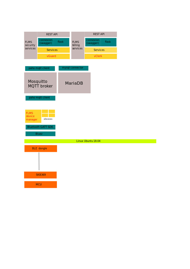
System Architecture
System architecture
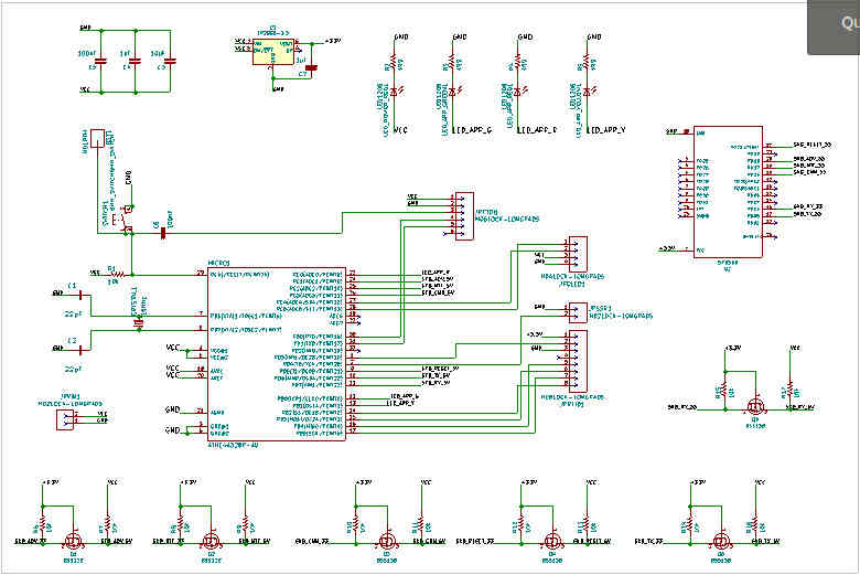
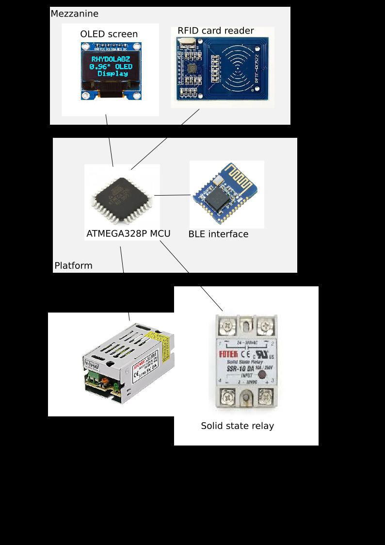
Hardware architecture
The architecture is organized around a ATMEGA328P MCU.
Software architecture
I'm a SW guy and I put too many details (most is out of scope) here but.. here it is !
Components
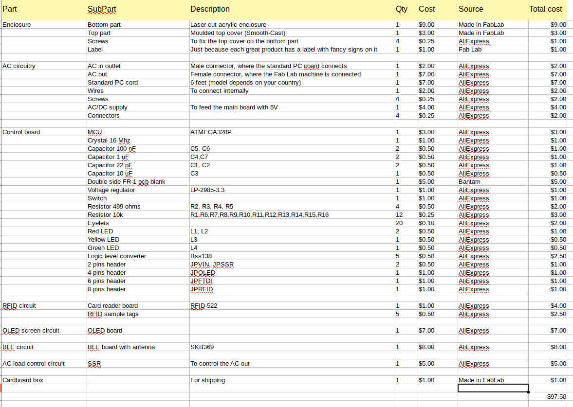
BOM overview
Here is a list of component, their cost and where they come from
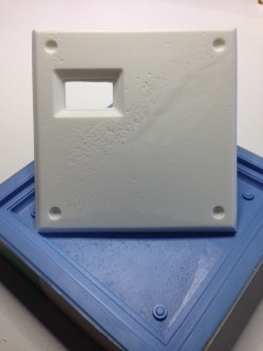
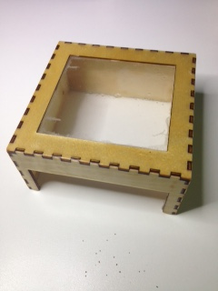
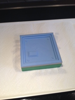
Enclosure
The main case, where all high voltage circuitery is located is a laser cut acrylic box. The cover is molded. I had multiple options for this enclosure. The best choice for a real mass production product should be to design a mold and to use plastic injection.There are numerous (and sometimes fancy) aternatives. See this site for more information.
My target is to include as many course learnings into my capstone project and I decided to go with a wood laser cut enclosure. It could have been printed as well. For the cover, I tried to use molding (vs 3d printing) to get a better finish. I changed my mind later because the OLED was not fitting well with the cover and I replaced it by a clear acrylic cover
AC circuitery
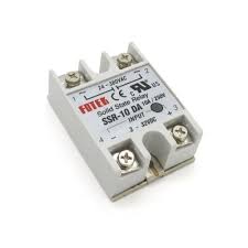
There are two outlets and one solid-state relay. One outlet to connect the device to the 110v wall outlet and another where the controlled device is connected. A 10A solid state relay controls whether the current flows or not. There is also an AC/DC to power the low voltage part of the device.
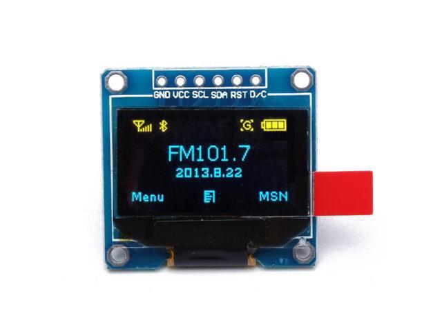
OLED screen
This is a compromise between cost, footprint and usability
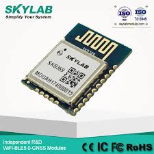
BLE module
This module suppports BLE, with an integrated antenna
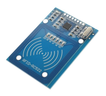
NFC tag reader
This module suppports ... with an integrated antenna
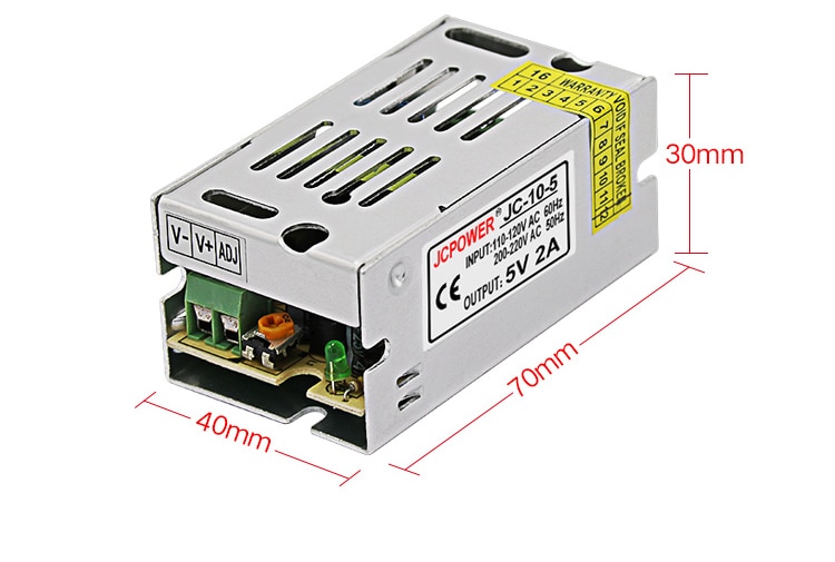
AC/DC module
I'm not sure I can build it on my own and what are the consequences in term of reliability and compliance but I could leverage this small module as a plan B
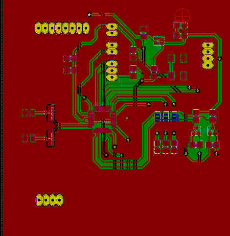
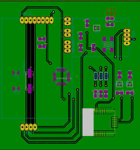
Carrier board
A fab lab made carrier board support all the other components: the OLED screen, the NFC card reader and the BLE card
Process
Overview of the processes involved
Here is a list of process and Fab Lab tools I will be using
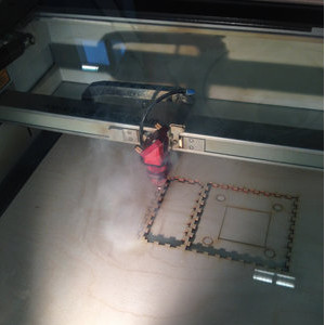
- For the cover, I tried three options:
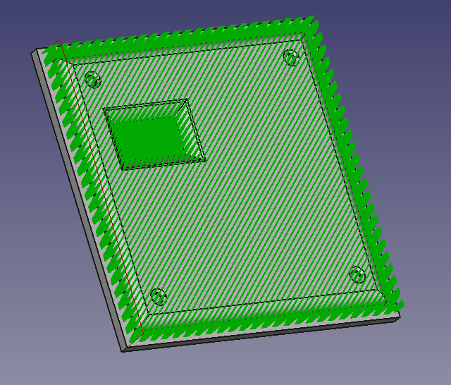
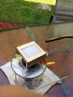
- Laser cut wood cover. I designed it using InkScape (custom Python script) and laser cut using Trocec laser cutterI will use TarBender epoxy to get a smooth and clean finish. Making a laser cut cover is easy but the challenge is how to include an opening for the OLED. I ended up with a quite large opening, which is not bad because I want to show the electronics. I tried to include an acrylic window and pour TarBender epoxy on everything but the finish is not great (but it fits the purpose: it is strong, water and dust resitant. The picture on the right is an attempt to pour epoxy over a complete PCB. I tried with another board with just an OLED. It worked well, the OLED is still functionnal. I did not with my final board, I have just one board and I'm afraid to make it burn !
- Casting and molding: I tried this a few weeks ago, I asked the team for their feed-back and the fact that I had visible screws on the top was badly perceived. The final part looks not good, this is not an issue with themolding, the problem comes from the reused wax I got from the Lab.
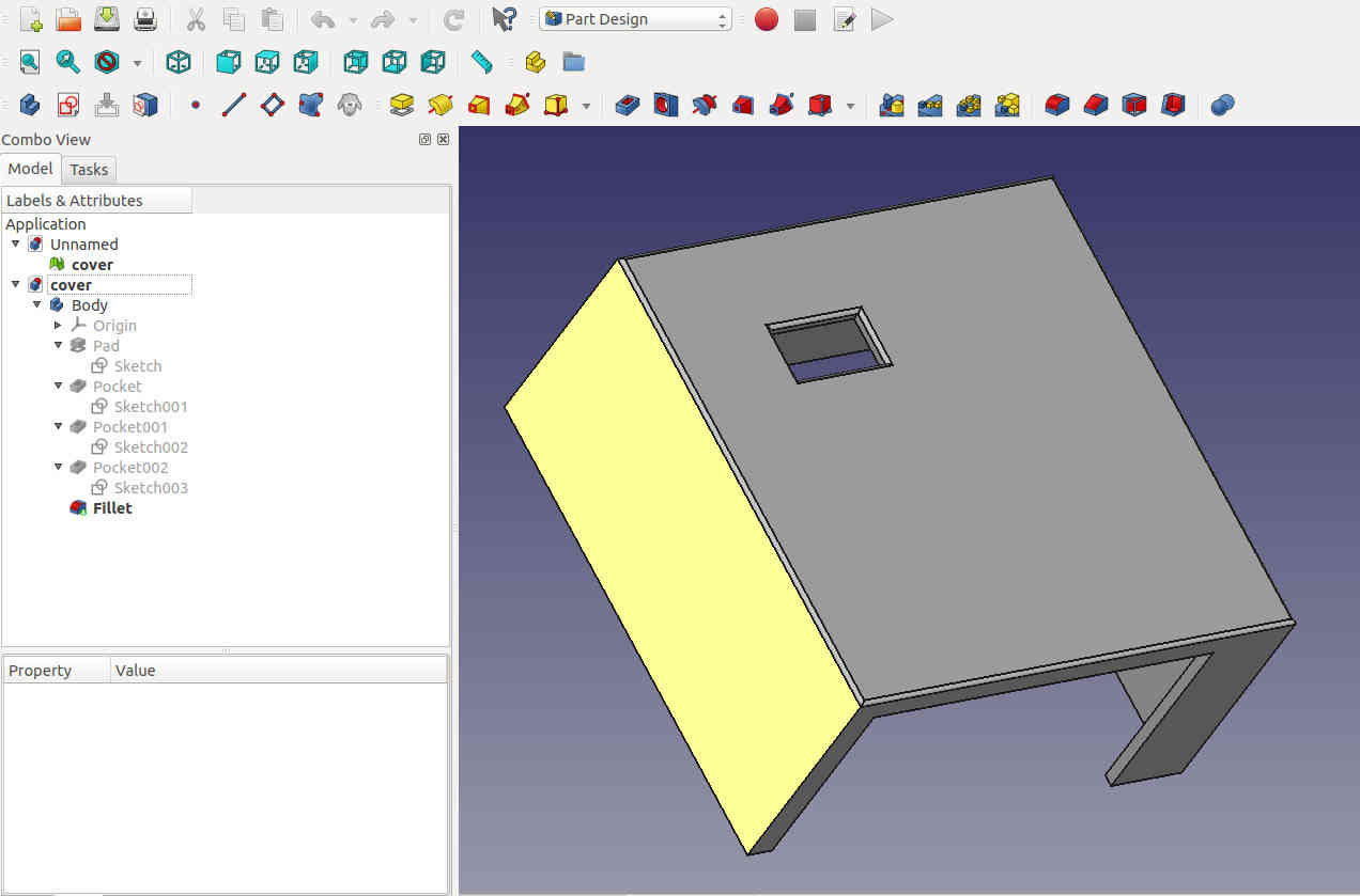
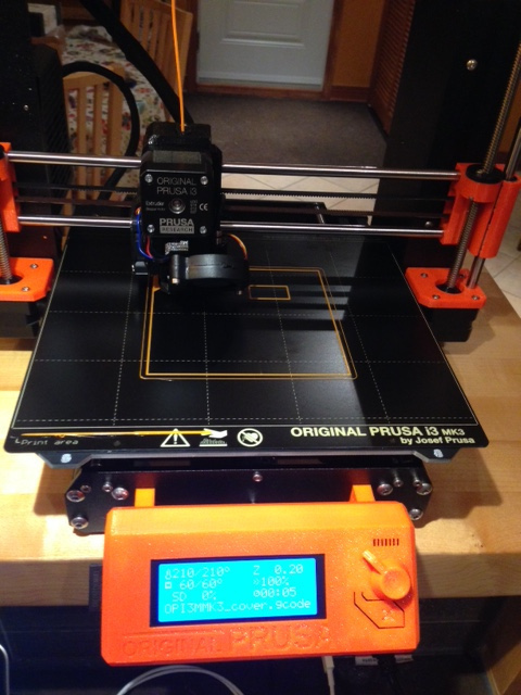
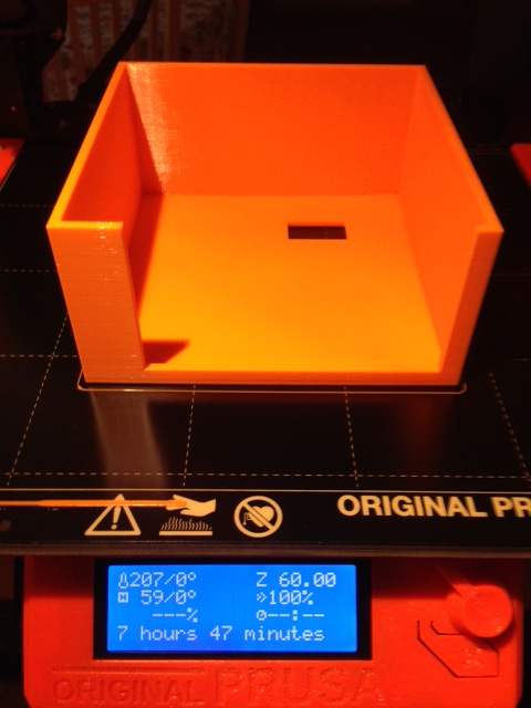
- 3D printed cover: I designed a PLA cover with a windows that fits the OLED. Here is how the model land the final result.
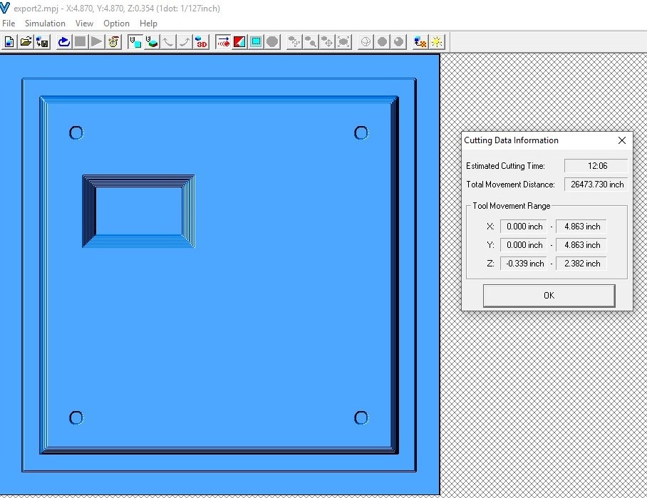
- The PCB will be designed using KiCad, milled on the SRM-20 CNC. I realized I cannot reflow a 2 sides PCB in my home made oven, so it will be soldered manually
Evaluation criteria
Here are the criteria
The ones that end with a star are Fab Academy evaluation criteria, the others are just mine
- PASS - Shall be student's own design (*)
- PASS - Shall demonstrate 2D and 3D modelling capabilities applied to student's design (*)
- PASS - Shall demonstrate appropriate usage of additive and substractive design techniques (*)
- PASS - Shall demonstrate student's competence in design, fabrication and programming of student's PCB-MCU and input-output devices (*)
- PASS - Shall be working (and not only once)
- PASS - Shall met a target cost under $100 (when manufactured in more than one item at a time)
- PASS - Shall be documented in a way that another graduated student could repeat it and improve the design.
IMPORTANT NOTE: since I was documenting as I was progressing through the course, I saved the documentation in different pages. To get a full set of up to date source files, click here .
- Week 4 - laser cut a draft of the product enclosure (wood) - DONE
- Week 10 - design a mold and cast a first draft of the top cover - DONE
- Week 11 - figure out how to connect the RFID reader to a MCU - DONE
- Week 12 - figure out how to connect the OLED screen to the MCU - DONE
- Week 14 - design, make and test a first version of the capstone double side PCB - DONE
- Week 15 - figure out how to connect the BLE interface to the final PCB - DONE
- Week 19 - setup the gateway (not part of the project but needed to test the device) - DONE
- Week 20- licensing - DONE
For the electronic part, I originaly started from the Satshakit design but I finally created my own. I kept files names as they were to inherit project settings, some footprints, design rules, .. and this is why it looks like a Satshakit spin-off.
Questions to be asked and answered
Open topics
- POSTPONED - Bluetooth MESH: for the time being I think it is not achievable since it requires a custom firmware.
- POSTPONED - USB: it should be great to control monitored device USB comm and not only the AC feed. If times permits..
- DONE - Groundplane or no groundplane... It looks it is a good thing to do but it is harder to solder: ok, I found a way. Just by adding more clearance, it is ok now. Eyelets between front and rear ground planes are still a little bit difficult to solder but it works
- FAIR BUT NOT PERFECT - How to get a nice looking and robust enclosure ? I decided to go with two parts: one laser-cut box for the structure and the AC circuitery and another one for the visible components.I tried a few things with epoxy but time was running faster than I would have needed. I ended up with a wood box with a clear acrylic window and TarBender epoxy poured on the top.
Ok... what about the future ?
My thoughts regarding the current prototype
- Enclosure: I realy like the idea of having a two parts enclosure. Thanks a lot to Annie Ferlatte for the informal brainstom on that topic. The bottom part contains all the potentialy dangerous parts (i.e the AC components) and the top part is a cover that protects against dust and other user-related problems (i.e dirty hands :-) ). I'm not that proud of the expoxy finish. It is costly, time consuming and the final effect is ... not so great. I see two evolutions paths from now. One could be to make the top cover out of clear acrylic but not sure it will resist to scratches... Another way would be to go with plastic injection but then the issue of aligning the OLED and to ensure it will be sealed will come back. Metal case is not an option since it will interfere with Bluetooth communications. Help needed here from people with more design and 3D slills than I have currently !
- Equipment control. It is ok to turn the power on a small CNC (ok but not nice... ). The equipment will live over it. It should be well better to cut the communication line when a user has no right (or no money) to use it. I think I need to control both: AC and comm. Another idea I had was to try to collect data out of the equipements (when possible). It depends on models and manufacturers but there are potentialy valuable data there.
- Networking: I missed time to give a chance to BLE MESH... I still believe it bring intresting opportunities when distance between equipements and the Fab Gateway is an issue.
- Fab Buddy Cloud App: non covered area, it is mainly a SW project, not so related to Fab Academy but still very important.
My thoughts regarding distribution
- Packaging and delivery. One of the 2019 students designed a delivery box for her project. Very professionnal. I would like to build one. I envision three ways to distribute Fab Buddies: one could be the current one (i.e you read my doc and you build your own). Another way would be to ship all components so Fab Labs could assemble their devices. Then I need to draw a line... waht should be pre-assembled and what should not... ?The third way should be to deliver final products (unpack and plug, that's all)