ELECTRONICS DESIGN | WEEK 06

A0 Link to group assignment.
You can see the group assignment hereIntroduction
The first thing to do for this week is choosing a program to design our board. there are many options but the most recommended are EAGLE, an Autodesk program free for small boards that can be connected with Fusion 360, or KitCad, an opersource program with many resources and plugins.
I chose EAGLE because I found more tutorials and resources in FabAcademy and I though that they would be very useful during the process. I download a educational version of the program and start from there.
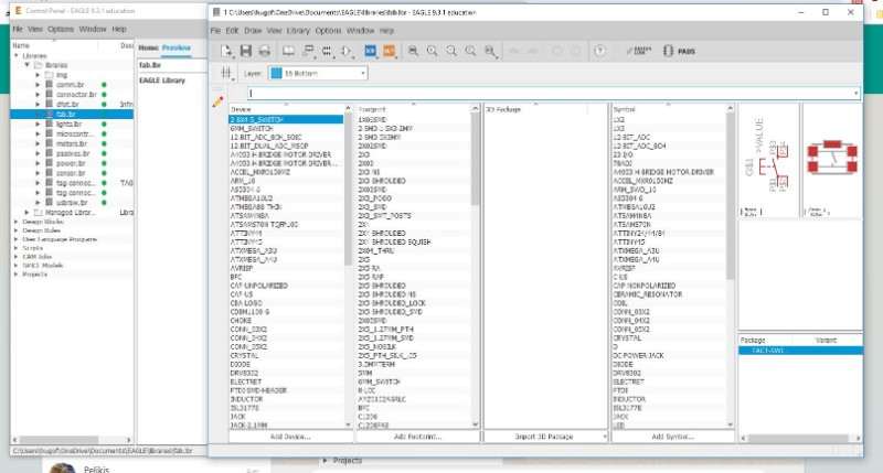
The first thing to do aftes download and install EAGLE, which is as easy as click in "next" a few times, is install the Fab Academy Libraries, they have most of the components that there will be necessary during the process.
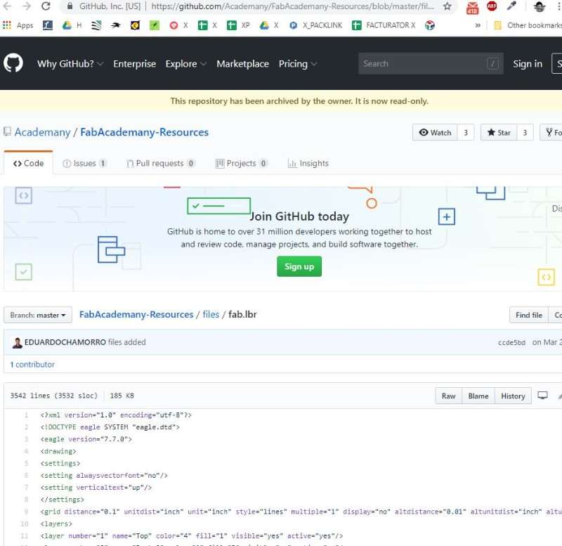
First option is to doing from GITHUB Fab.lbr but it didn't work for me. The process is easy: donwload the file and and save the file "Fab.lbr" in your EAGLE folder, in my case, It was placed as default in Documents/EAGLE/Libraries.
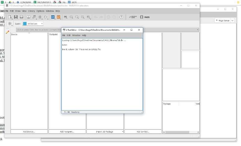
In my case I got my first problem: When I tried to openned (which you can do in EAGLE control panel/libraries) I saw the message that you can see in the image above:"This is not an EAGLE file" ummm very interesting.
I read somewhere that it could be a problem with the Route, so I created another folder called "EAGLE EXTERNAL LIBRARY"
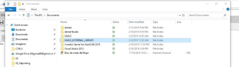
With the same result...
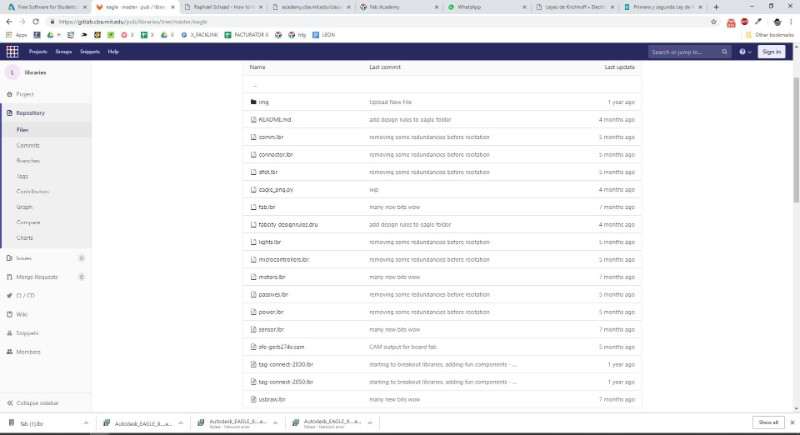
At this point I download again the file and found the same problem and started to think that I was using a wrong file and try another way. I've found that you can also download the file from GITLAB, where there is a bigger library with more files. I download this one.
...and problem solved. It's time to start with the the design process.
EAGLE works with two "programs" the SRC and the BDR. The first of them is more schematic and we use it to connect the components and test the circuit, when everything is done we can save the file and start with the BDR, which shows every component in it real size and the connections between the wires.
After install the FAB library we have all the components that we need of our circuit. Now We have to add them to our schem. The components that we need are:
- 2 x RES-US1206FAB
- 1 x ATTINY44-SSU
- 1 x 500k RES-US1206FAB
- 1 x 6 pin header AVRISPSMD
- 1 x 1 uF CAP-US1206FAB
- 1 x LED 1206
- 1 x 6 pin header FTDI-SMD-HEADER
- 1 x 20 MHz RESONATOR
Using the command add Eagle opens the library and we can look for the correct component there. We can disabled some libraries to make easy the search of the specific components. I started with the ATTINY44 and connected to the ground and the power, after this I followed with the rest of the components.
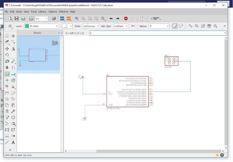
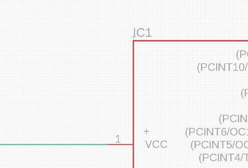
There are two ways to connect the component: By nets or by Labels. I prefered labels because it makes the schematic more clean but I think that they can be a problem in a bigger circuit because you can not see viually a line connecting both elements. To define a label you have to create a small wire and difine it with a label. You can type "net" or "label" there are visual buttons in the left menu to use this commands
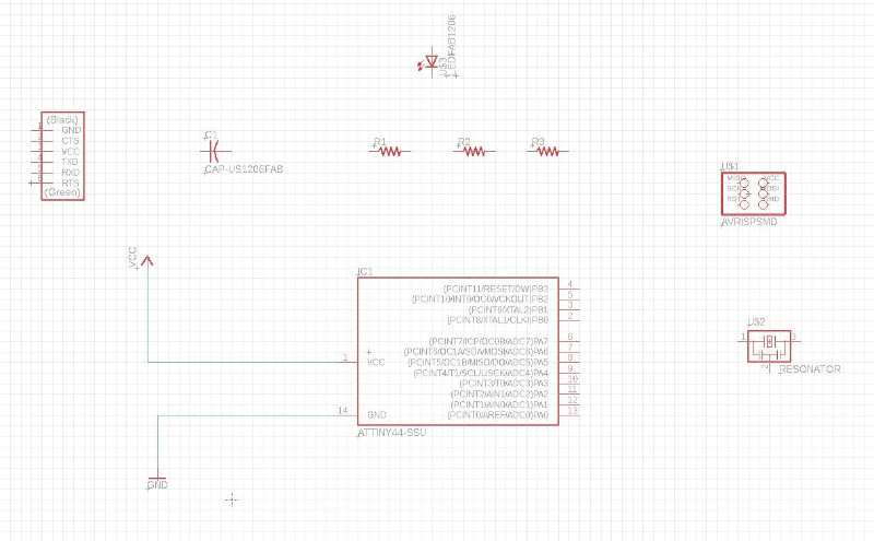
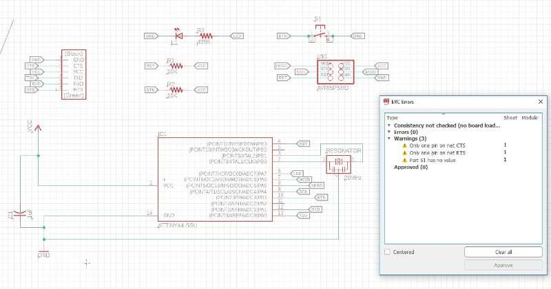
when everything is connected is more than recommended to use the command "ERC"it will check everything and shows you the problems in your design. In my case the problems were related to elements that I didn' need to connect. So I approved them and click BDR to start with the real design of the PCB.
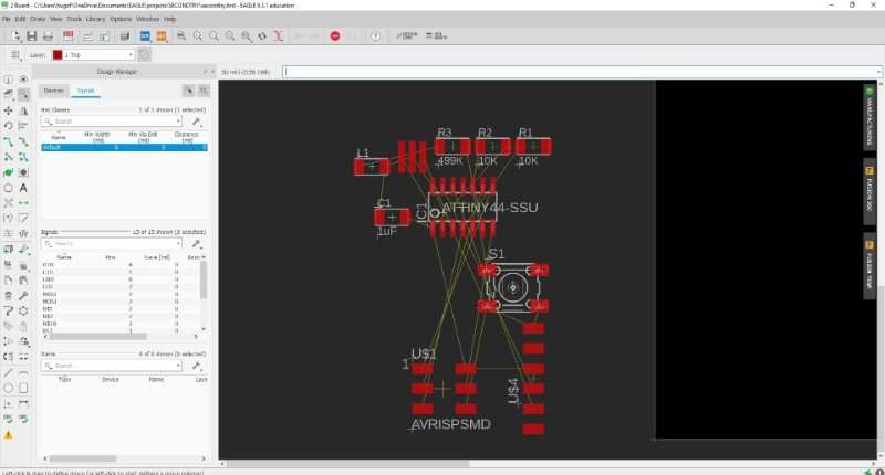
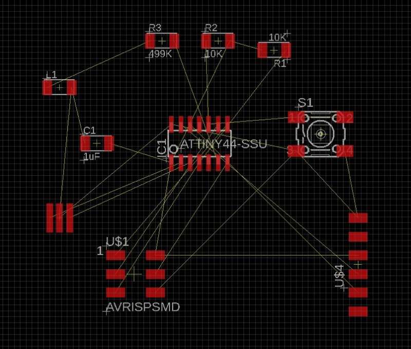
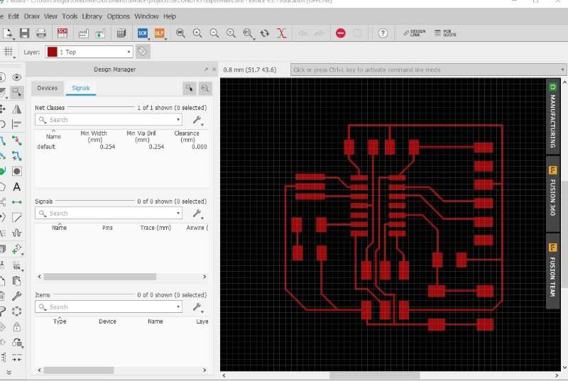
This is how the BDR looks when you open it for the first time, a mess of components connected by yellow wires in any way. So the first thing to do is find some order and move them in a sort of way that make the mess looks less messed.
Then I've tried with the option autoroute, that draws the routes for you. I thought the computer would be smarter than me (it's not so difficult) but the result wasn't very useful..
I tried againg with other configuration... but I had a similar problem. Anyway I thing is interesting to do the autorouter before start to make the routes by your self because it gives you a vision of the whole thing.
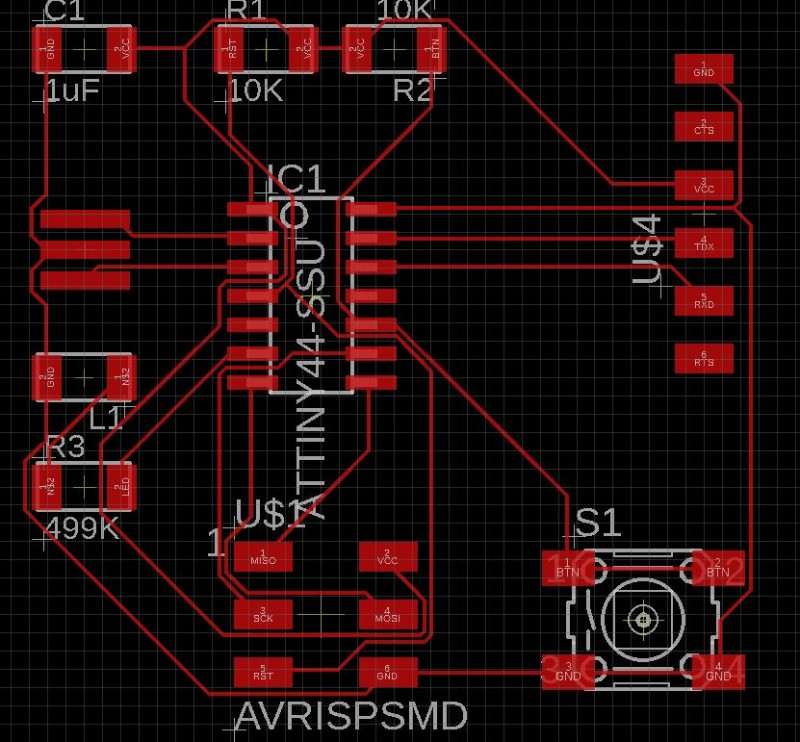
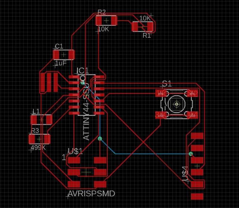
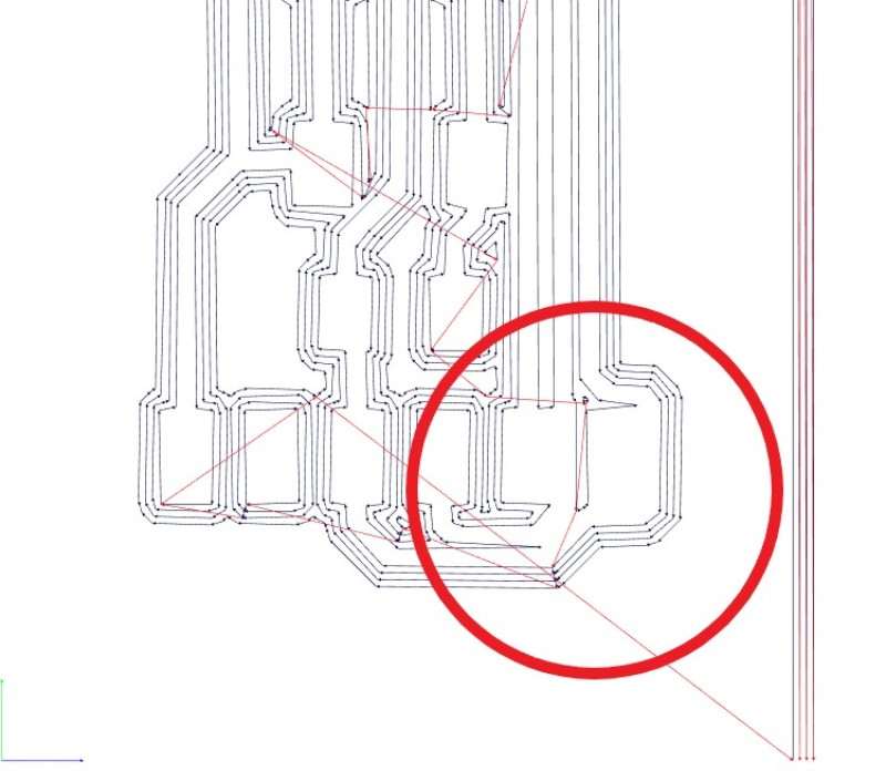
Based on the autorouter ideas I made my own connections and the looked great!
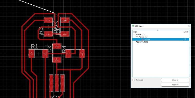
then I used the DCR command and see that they were many thing to correct: clereance, wirestub, air wire..
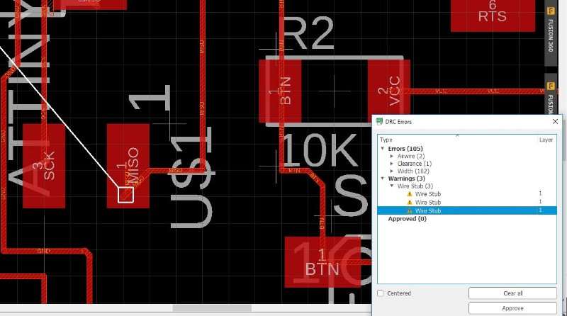
At this point I discovered something beautyful. I forgot to insert the define rules archive! So all of my routes were wrong sh...
Going Lazy
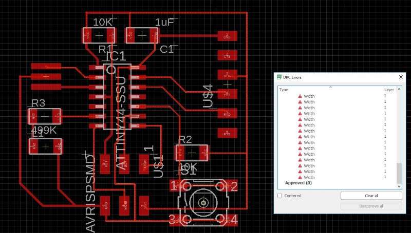
I've looked in internet for a solution to change the width of all of them at the same time and found a "ULP" in an AUTODESK forum that lets you doit by this way
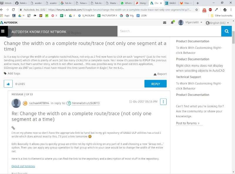
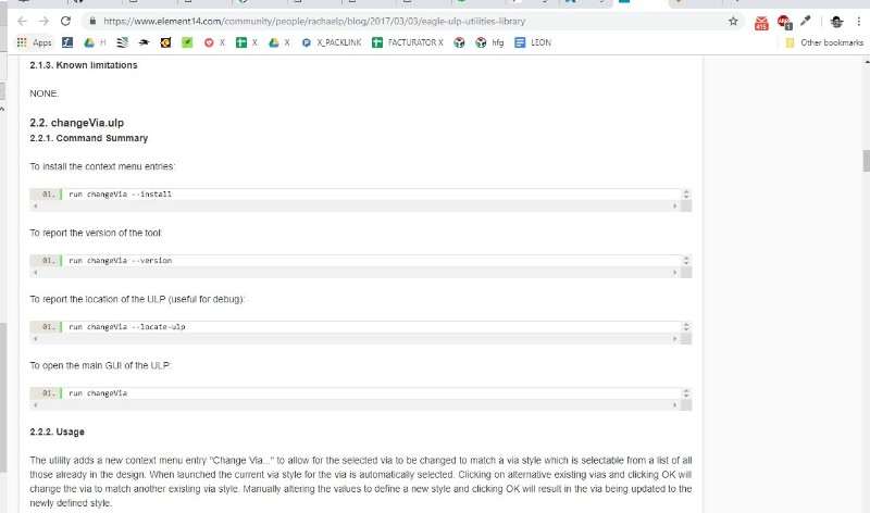
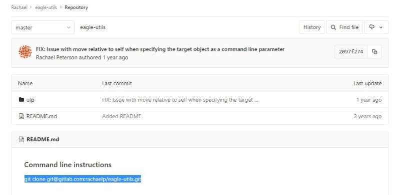
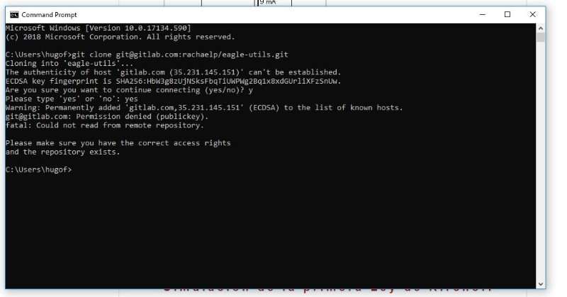
I followed the instructions and it didn't worked so I finally had to redraw the whole thing one more time... But I wanted to tell here, maybe it's useful for other person, don't know.
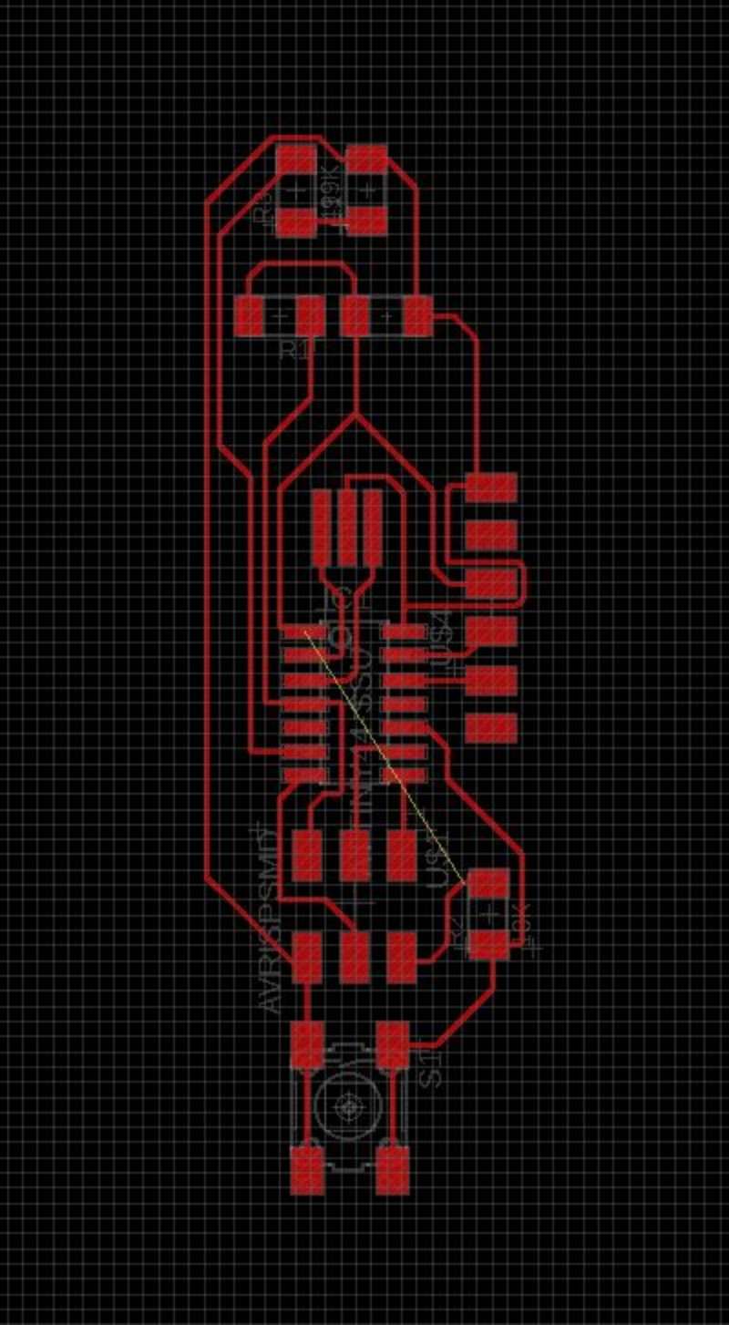
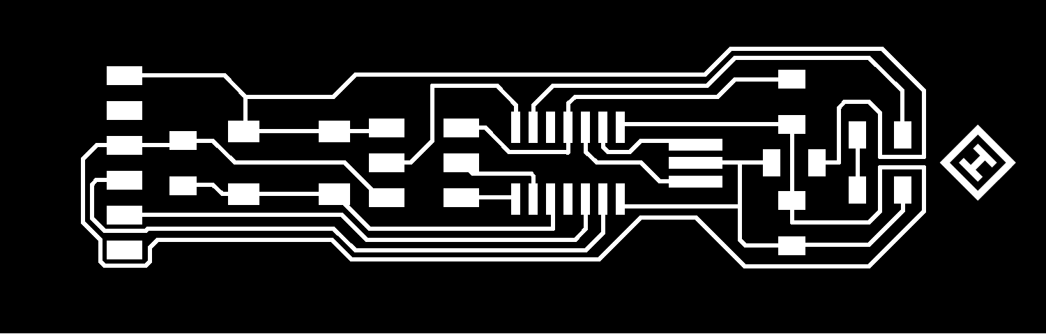
This is my final design. Now, to mill them I need to export it as PNG: File> Export> Image Choose the resolution (500px at least) monochrome and clip board
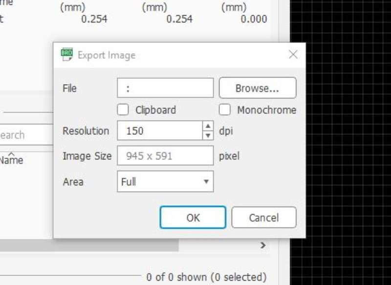
The result image can be manipulated with photoshop or illustrator to create the bordes and add a logo or signature.
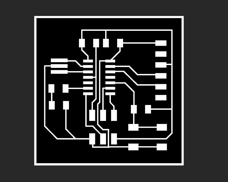
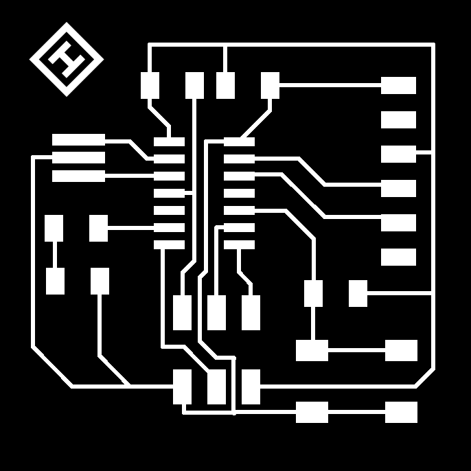
Here you have my final images as they are before sent them to the Roland machine for milling.

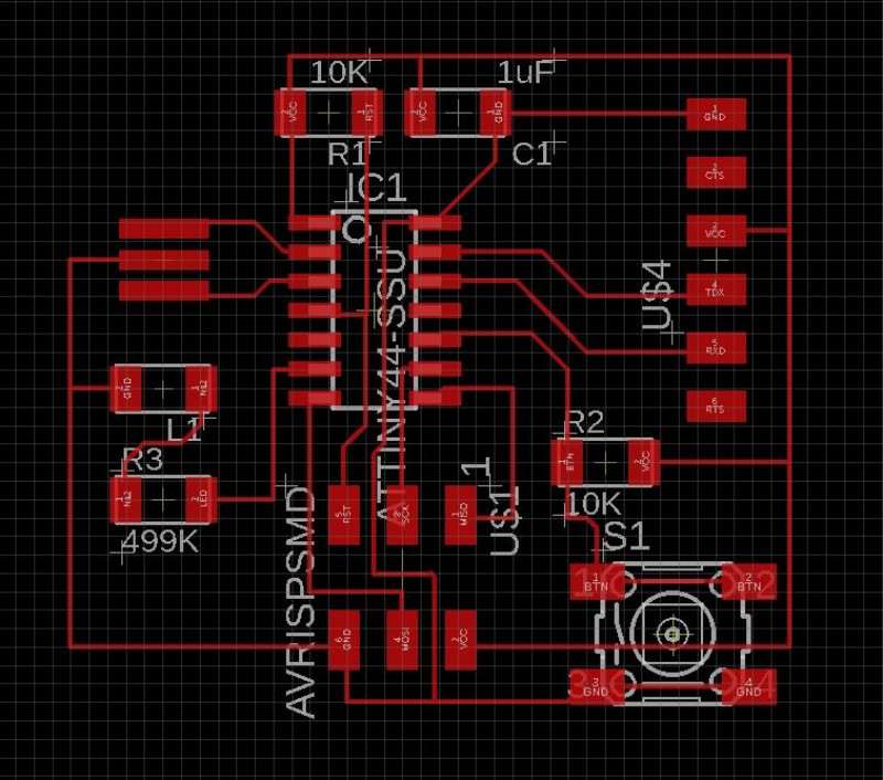
I wanted to play a little more with the program so I designed a second PCB with two ideas in mind separate the most possible the button from the LED (create a board only to turn on a LED when you push a button doesn't sound very useful so, at least i wanted to put the led far away from the button and, I wanted to create a symetric board or as symetric as I could get.
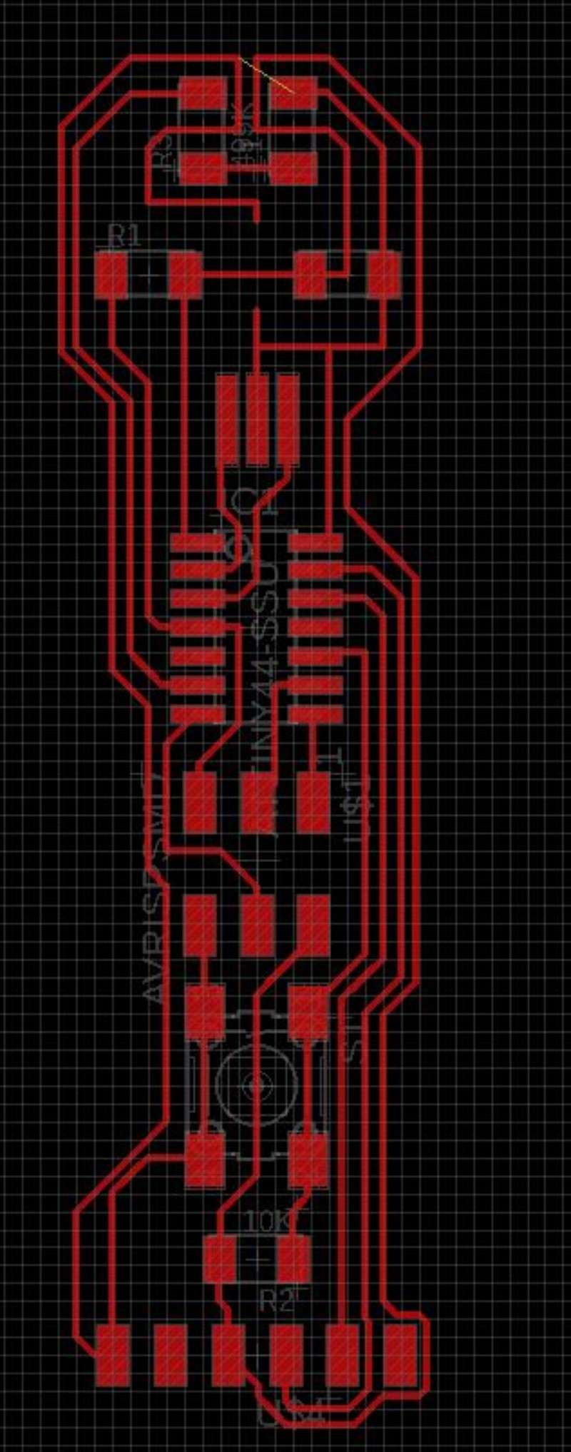
It wasn't easy, believe, but I finally got a solution with only one problem: I need a bridge to connect one of the wires... ummm how could I create a bridge in my circuit? Using a resistor of 0K
Now I have board ready to mill. I exported again and edited with photoshop. This is the result:
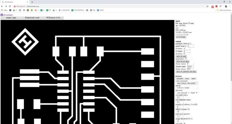
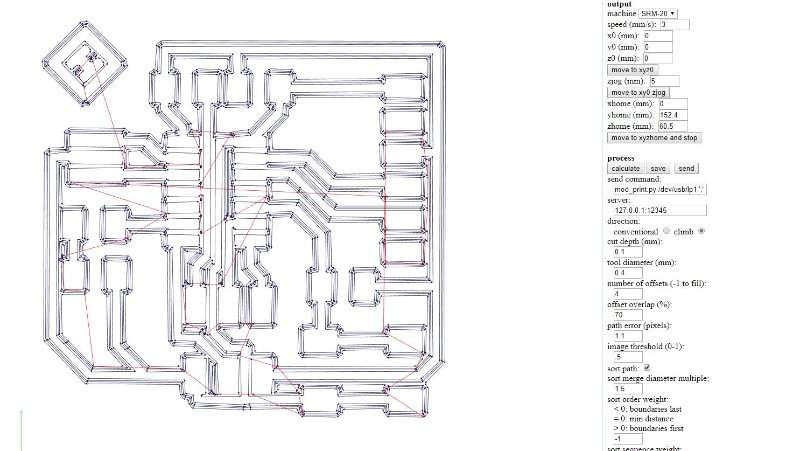
With the PNG files ready I used Fabmods to create the archive for the milling machine, I did the same steps than in the assignment of two weeks ago Electronic production
.jpg)
Experience is a grade like people said and this time I didn't have as many problems as the first time and both boards cut pretty well. Here you can see it.
.jpg)
.jpg)
I had some design problems in my second board, the long one and some of the traces where to close for the machine to mill them correctly.
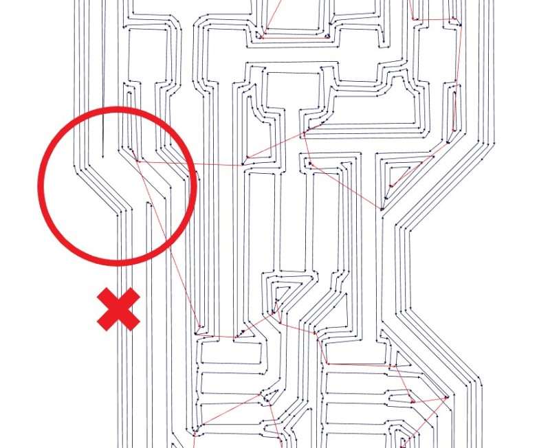
I tried to fix them with a cutter and tin and after test continuity with the multimeter I decided to let them like that and don't mill the board again.
This was a real adventure. we didn't have any tutorials for the testing and it's something that nobody had to do in the previous years so we were alone in this part.
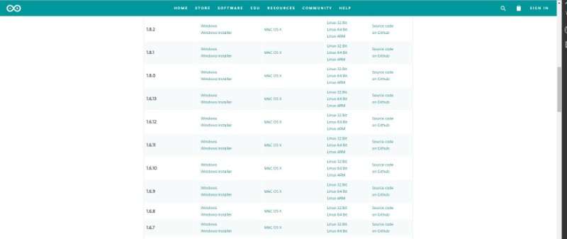
I started by donwload arduino IDE to run the program in my PCB. First I download the latest version but it wasn't so stable as I need and finally donwload the 1.6.5 version. It can be donwloaded from here.
First thing to do is download the library with the Board manager for a ATTINY44. To do this I followed the tutorial from this webpage highlowtech.org. Here is here I've founded the link to the library that I need is this: https://raw.githubusercontent.com/damellis/attiny/ide-1.6.x-boards-manager/package_damellis_attiny_index.json
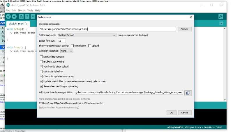
In File > Preferences I copied the link in "additional Boards Manager URLs.
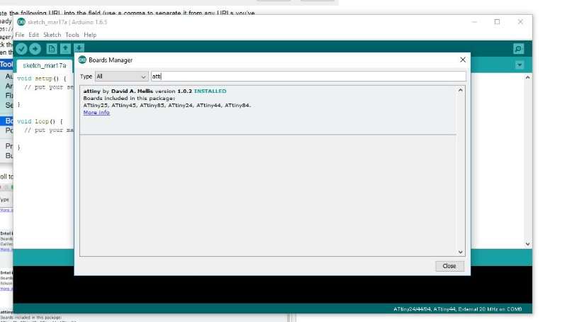
After that, I looked for the attiny in the boards manager Tools > Board > Board manager, and installed the package of David A. Mellis
The I difine the board options in the tools menu like this:
- Board: ATtiny 24/44/84
- Processor: ATtiny 44
- Clock: External 20MHz
- Port: COM6 (depends on the USB that you are using for the programmer
- Programmer: USBtinyISP
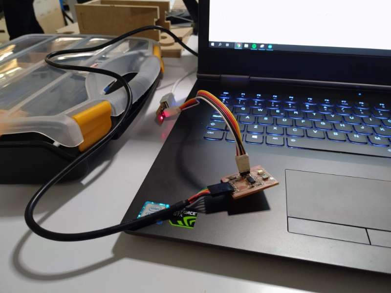
After define all this values the first thing is connect your programmer to the computer, the board to the programmmer and to the computer using a FTDI cable. then you can run the bootloader.
But when I run the bootloader something went wrong.

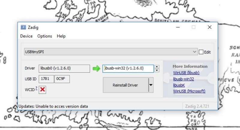
I thought it could be that the computer wasn't recognizing my usb so I run zadig again to install the libraries
When I tried again the bootloader worked and I could download the program for testing this program
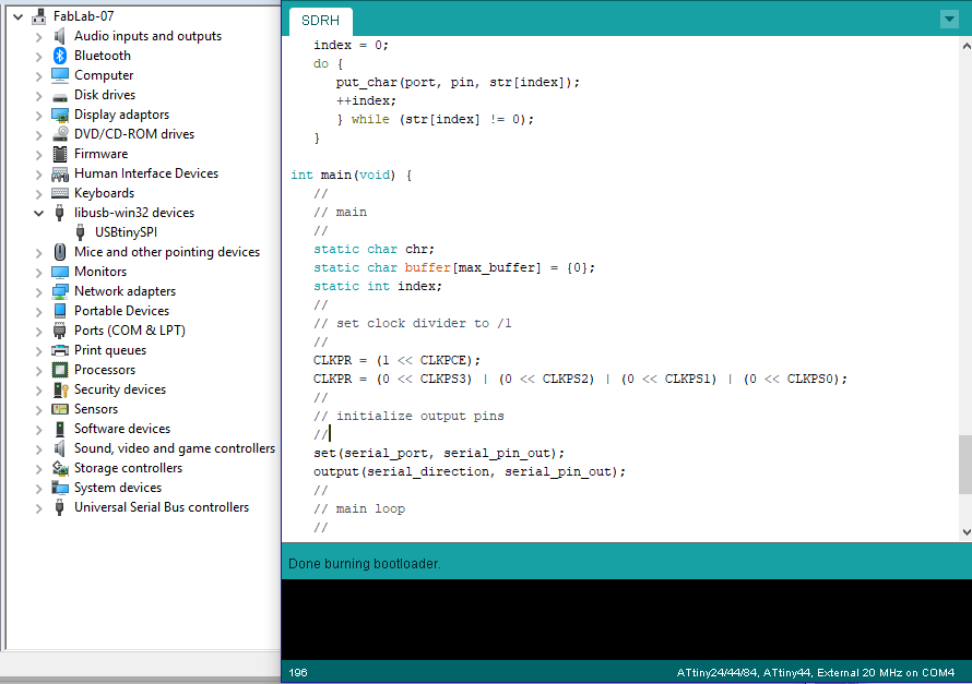
The download went well and I could install the program but the echo wasn't correct. Something wasn't working in my PCB...
Electronics gave me a break for one time. First I thought that it was the resonator becouse I programmed the board to turn on the led always, at first it didn't work but when I touch it (to through it away probably) the led turn on I undestand that it was a problem with the connections. I sold the resonator again and programmed again my board... but When I open the serial I found this:
.jpg)
The board wasn't communicating at all until I touch something there and It started to send symbols and nonsense. I got back again to the table and sold everything again. this time it worked fine. Yes!!!
.jpg)