CONTROLLED-COMPUTER MACHINING | WEEK 06
A0 Link to group assignment.
You can see the group assignment here.jpg)
This is my first time with a cnc machine and I am very curious about how it works. Neil's explanations sound terrific and I could see that there are many options and possibilities with a milling cnc machine. I wanted to run before walk and started with a 3d piece but 2d cut and pockets it is a better way to learn what we can do with a monster machine like this.
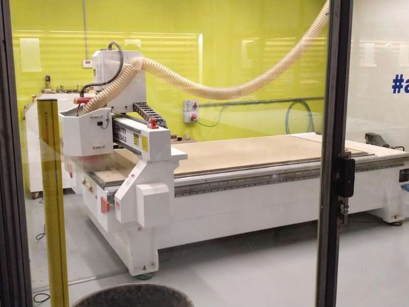

Our machine is a "PerezCamps milling machine" with a maximum cutting size of 2500x1500mm, perfecto for the standard panels of 2440x1220. For the exercise we will use MDF of 10mm os thickness, which is nos very much but works fine for our experiments.
Some references
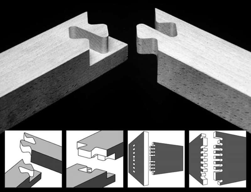
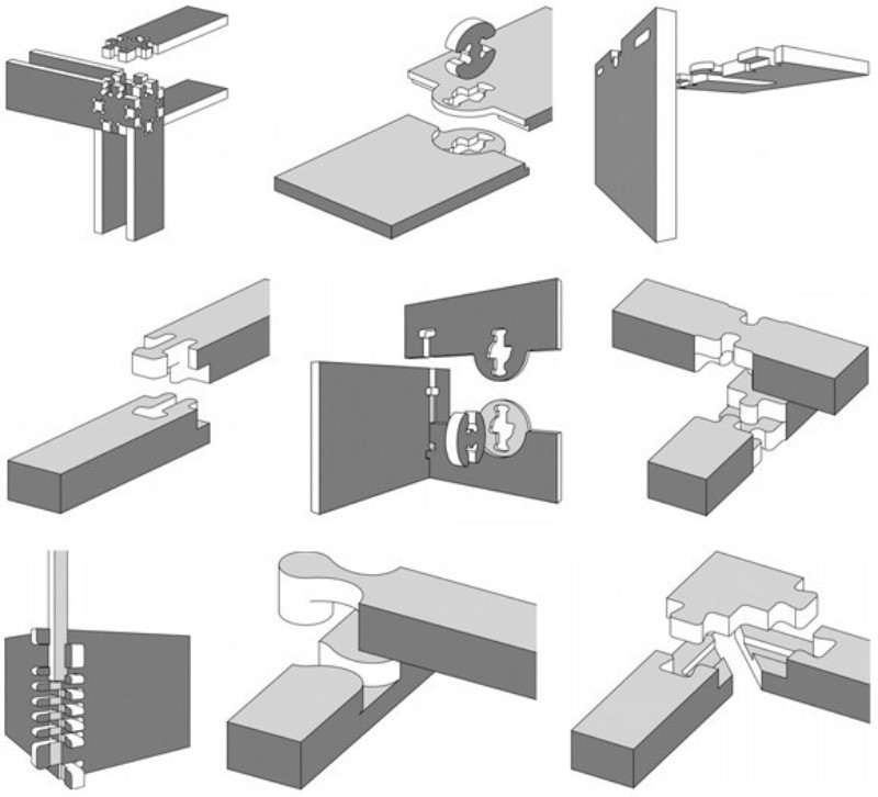
I was very interested in try some of the cool joints typical from japanese woodwork, there are many websites explaining them and how to adapt them to cnc machinery. Here are some of them.
 Good examples and files to download, in english and german
 Other kind of joints with examples are available here
This one C is not very useful for cnc machine (most of them need to rotare pieces and works better with beams and thicker pieces of wood but they are very interested and the gifs helps a lot to understand how they work ando the precision of the japanese way of woodwork.
Other kind of joints with examples are available here
This one C is not very useful for cnc machine (most of them need to rotare pieces and works better with beams and thicker pieces of wood but they are very interested and the gifs helps a lot to understand how they work ando the precision of the japanese way of woodwork.
Lets make something (but not big yet)
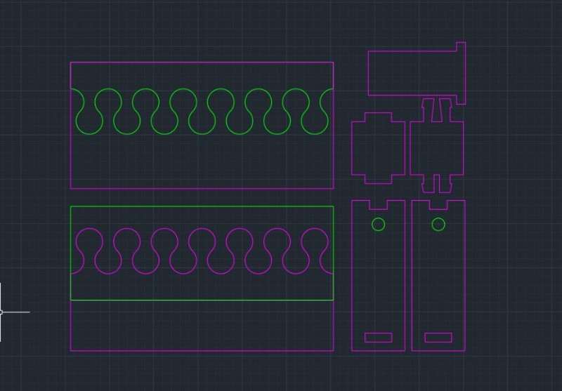
The first thing that I wanted before even think about something big to do is see the machine working and cut some pieces that need to fit together, so I create this file to try different options and fittings: A half-lap joint, a encaster and a rotary piece between two circular pockets.
They didn't worked as well as they could be it's fine for me. I wanted to see the tolerances that I would need to apply in my "big" project and learn how to prepare the "TAP file" in CUT2D pro, the program used in IED's Fablab. I learned that:
- 1. encasters I need a tolerance of 0.4mm an least, which means 0.2 in each piece.
- 2. Careful with the corners, specially the 90ª ones that will fit in a hole. A CNC machine is not like laser and the mills have a minimum diameter so interior corners that not exist really. This can be fixed by putting holes in the corners but the apparence of the of the joint will look rare (at least for me)
- 3. It's important to go down that the thickness of the board to hace a good cut. Also, if we don't use taps (littles pieces that the machine doesn't cut) the pieces will fly/break the mill/ make the fablab burn... So, believe, use taps always
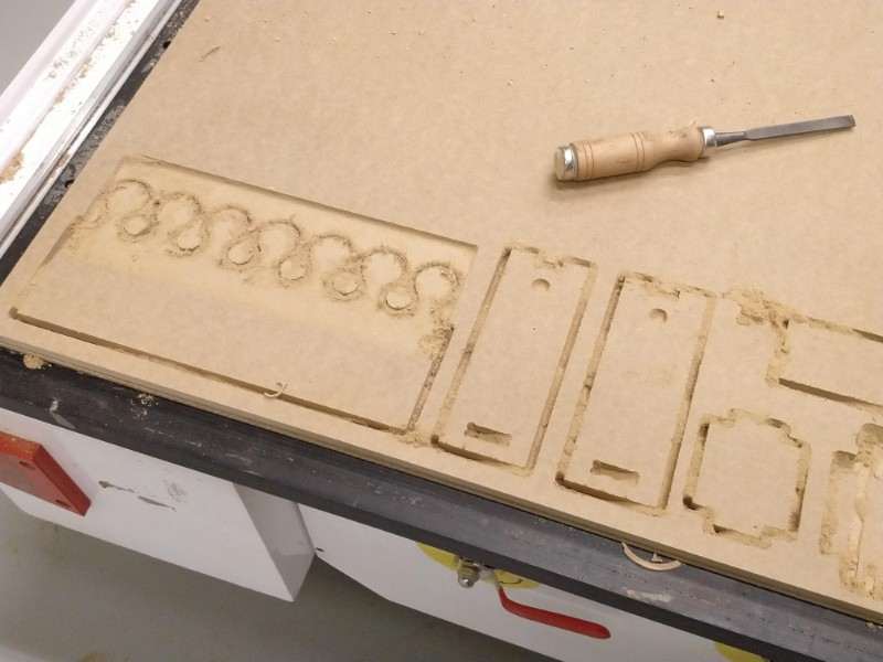
- 4. If you are cutting MDf sandpaper and a flat file will be your friends. A chisel (I didn't know this word in english before) is most than recommended for take off the taps (if you try to take the parts of the board with out it you will break the surface easily).
Here you can seehow the experiment went. The pocket for the rotation worked and the ecaster too but the last one with the circles din not worked
.jpg)
.jpg)
.jpg)
As you see a hummer is not the solution for fix a half-lap fitting... Also, MDF is not as flexible as I thought...
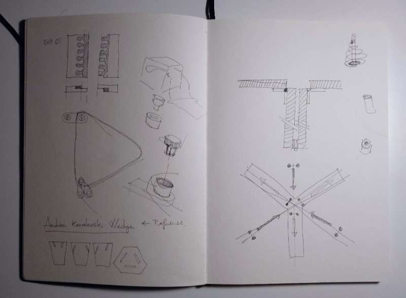
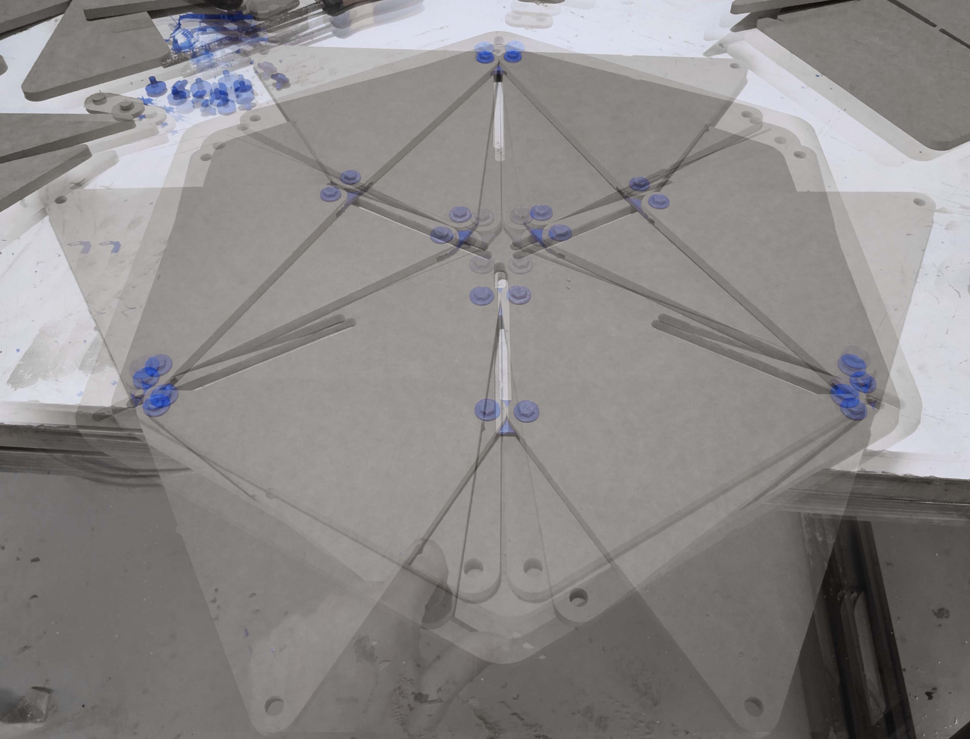
I've had many ideas for the cnc machine but I wasn't sure about any of them. It the laser assignment I had the opportunity to work with a big laser cutting machine and cut mdf of 10mm and use a cool joinery and I also tried flexures so I didn't want to spend the week doing the same. I focused in think about something related with my final project and adapted one of the modules to a 2D solution. By this, I wanted to explore how to connect the different triangles and move them at the same time.
.jpg)
At some point I though that I don't wanted to do only a prototype with out purpose so I mixed the prototype with the idea of a expandable table.
.jpg)
.jpg)
It made me expend the whole afternoon drawing and re-drawing the different parts in rhino and finally ended with amixed solution that uses 3dprinting parts for the union between the triangles and the hexagon table.
.jpg)
I divided the pieces in two archives: one for the cnc machine and other for the 3dprining machine.
.jpg)
.jpg)
With the files ready it's time to put them in the big cnc and wait to see if I made some mistakes (hopefully there won't be any) but first i prepared the archive for the cnc machine as you can see here.
First I defined the mill that I was going to use
.jpg)
Then I prepare the cuts. I divided in three: First the pockets, then the interior cut and finally the exterior cut.
.jpg)
It's important to create tabs to avoid injuries to the machine, tabs mantain the pieces in his places until the machine has stopped.
.jpg)
Finally I made a preview to see the work of the machine and ensure that there are not big mistakes here.
.jpg)
.jpg)
It's time for the machine to work and for me to rest (and eat something) or maybe for documenting all these things... :(
.jpg)
After an hour or two I get the pieces that I wanted and know take it off using a chisel and a hummer
.jpg)
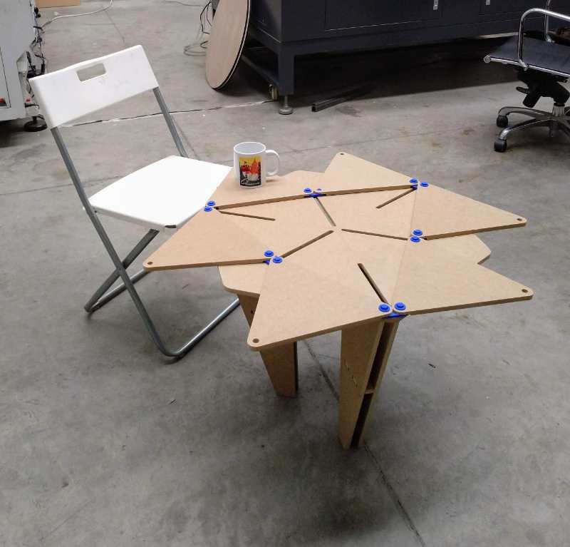
It looks like I cut the parts of my table correctly because everything is going fine now. I mounted everything without error (it was a good idea to use rhino and model everything in 3d) and some patience.
.jpg)
.jpg)
After I confirmed that the table was right I put the 3dprinted parts and see how the table moves.
.jpg)
.jpg)
My conclusion is that it needs some improvements but it's not bud as a first prototype. Probably could work better with another material that reduces the friction.
The hero gif shot !!
...And a real hero shot with the table finished