EMBEDDED PROGRAMMING | WEEK 08
A0 Link to group assignment.
You can see the group assignment here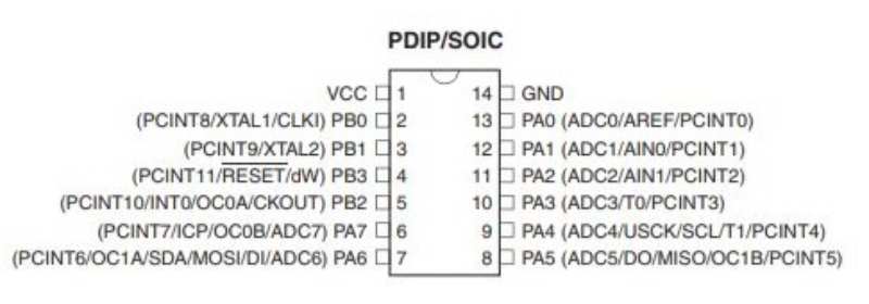
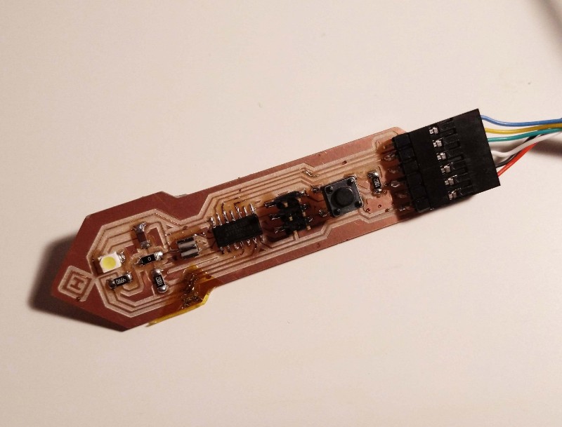
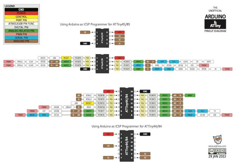
The Attiny 44 is the second microcontroller that we use (first was the Attiny45) The data sheet is huge (about 300 pages) and it contains much information. It's good to read everything carefullly so it will be easier to know where to find the most useful parts in other data sheets.
First Page works as a resume and explains the characteristics of the microcontroller. These are some of them:
- 12 programmable pins (plus VCC and Ground)
- Flash Memory of 2k/4k/8k
- Internal RAM of 128/256/512 bytes, this is important for the size of the program that it possible to use.
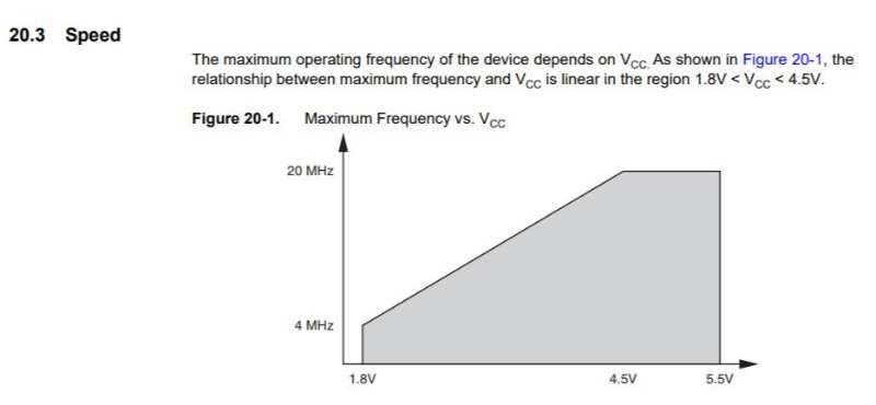
- Speed grade: From 4 to 20MHz. It's connected to the VCC power (more power, more speed) It's also important to know that the internal clock is only 8MHz for more speed is necessary a external one.
- Voltage: 1.8 -5.5V. We usually work with 5.5V
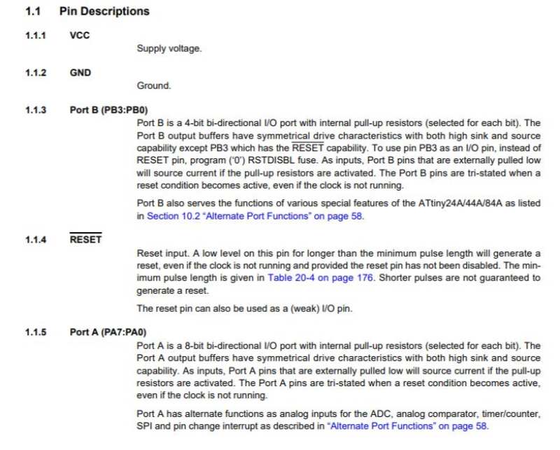
In the image above it also possible to see the different type of PINS. Some of them as MISO or MOSI are basic for comunication. There is also only one that can work as RESET. The description of each Pin is explained with more detail in the next page
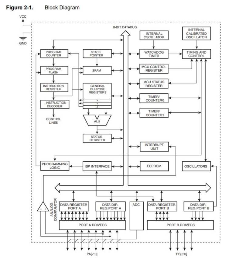
There is also a diagram explainning the connections between the PINS and the internal components of the Microcontroller. I don't tink that this is very important to use the microcontroller at the level at we do. But it made me understand better the use of each PIN.
FLASH MEMORY
I guess that the important part here is the size of the flash memory. 2k/4k/8k organized as 1024/2048/4096 x 16 I guess this is important to know the how big is the program that we can put inside the microcontroller but is very technique for someone like me. So, here is my first question What's flash memory and how can you mesure it?
INTERNAL AND EXTERNAL CLOCK
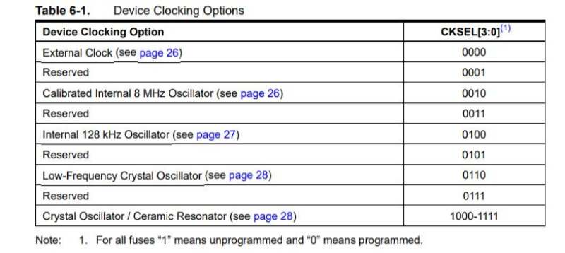
In last exercises we have use a resonator to create external clock of 20Mhz, here is the reason why we had to do it. The Microcontroller has only a internal clock of 8MHz. For more is necessary a external solution. So here is my second question What's the clock and when do I need a slower or faster one? I searched in google and looks like the clock mesures the internal time of the microcontroller, which is needed for some devices and processes (for example to avoid delay?) I guess that 20MhZ is more precise than 8 Mhz.
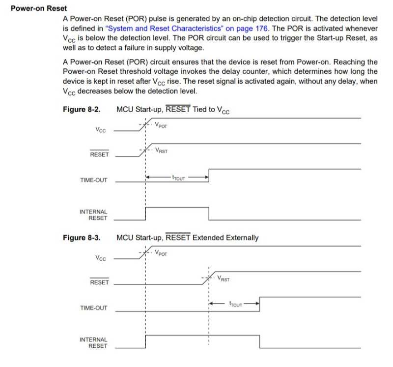
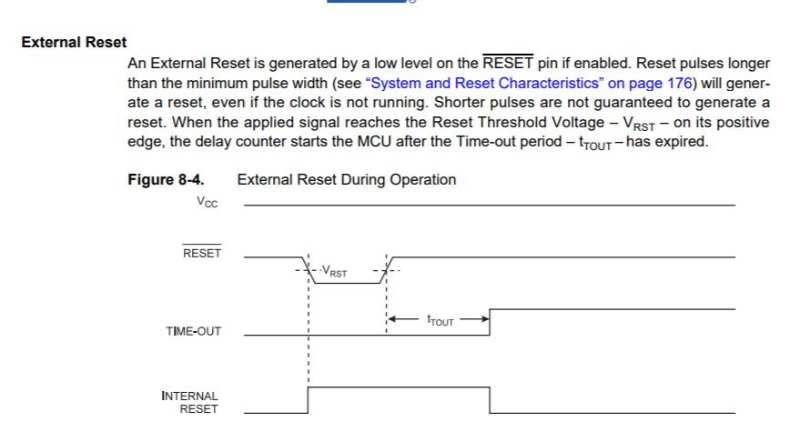
RESET
Here is the explanation for the connection between the ground and the VCC in most of NEIL'S boards, it's the way to make the RESET works. It also explains the difference between the internal and the external RESET
Speed
Finally, It's very interesting to know that speed is connected to power. This is important because a bad supply can make the microcontroller work wrong.
As starter for this week I used Arduino IDE. The same version that two weeks before (1.6.5) And started that with the basic examples that the program has. There is a big list of examples with pre-coded programs that can be modify to learn. So after some basics about the syntax of the code i openned my first code.
Some important tips about arduino's Syntax:
- -Void Setup: Commands that only runs ones (at first)
- -Void loop: Commands that will run without end (usually where the options goes)
- -Variables goes before. Variables are the "names of each element in the code. We use to define the Pins from the board (for example)
- input/output In arduino is necessary to define which varibles are "INPUT" and which are "OUTPUT".
- Digital / analog-Variables can be Digital (two options: 0 / 1) or Analog (1,2,3...1024)
- -Logical commands: Commands as "If(...) {....} Else {....}. Other commands could be && (and) and " (or)
First thing to do is install ATTiny44 board manager, which I did two weeks ago during the "Electronics design week" with everything configurated it's possible to send a program to the processor with success. After that step we can open the Button file example from arduino File > Example > Digital > Button
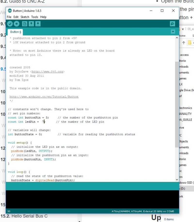
the first thing to do is define constants const with the pin that they will refer to. Arduino has a different name for any pin than the the C code so it's important to know the correspondance between them.
In my case the Constants would be these ones:
- LedPin = 7 (PA7 in my tiny44)
- buttonPin = 3 (PA3 in my tiny44)
with these parameters modified we can try the first program. Compiling...
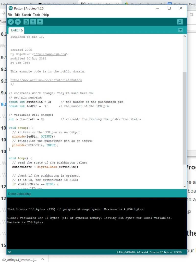
Compiling done, Lets see how it works
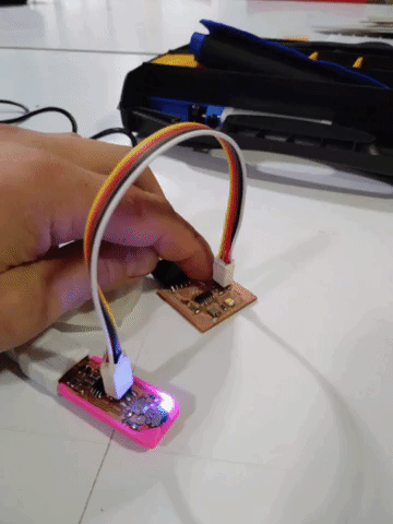
Wow! It works.
Code can be found here
.jpg)
Other way to programming the board is using the bash and the C language directly. To learn who to do this I used this tutorial and it was pretty easy:
Download and save the files
- hello.ftdi.44.echo.c
- hello.ftdi.44.echo.c.make
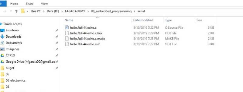
Then open git bash from the location and run two commands:
First: sudo make -f hello.ftdi.44.echo.c.make program-usbtiny-fuses (These is not necessary if you set the fuses in Arduino using the Bootloader, but I did it anyway.
Second: sudo make -f hello.ftdi.44.echo.c.make program-usbtinythese flash the program into the ATTiny
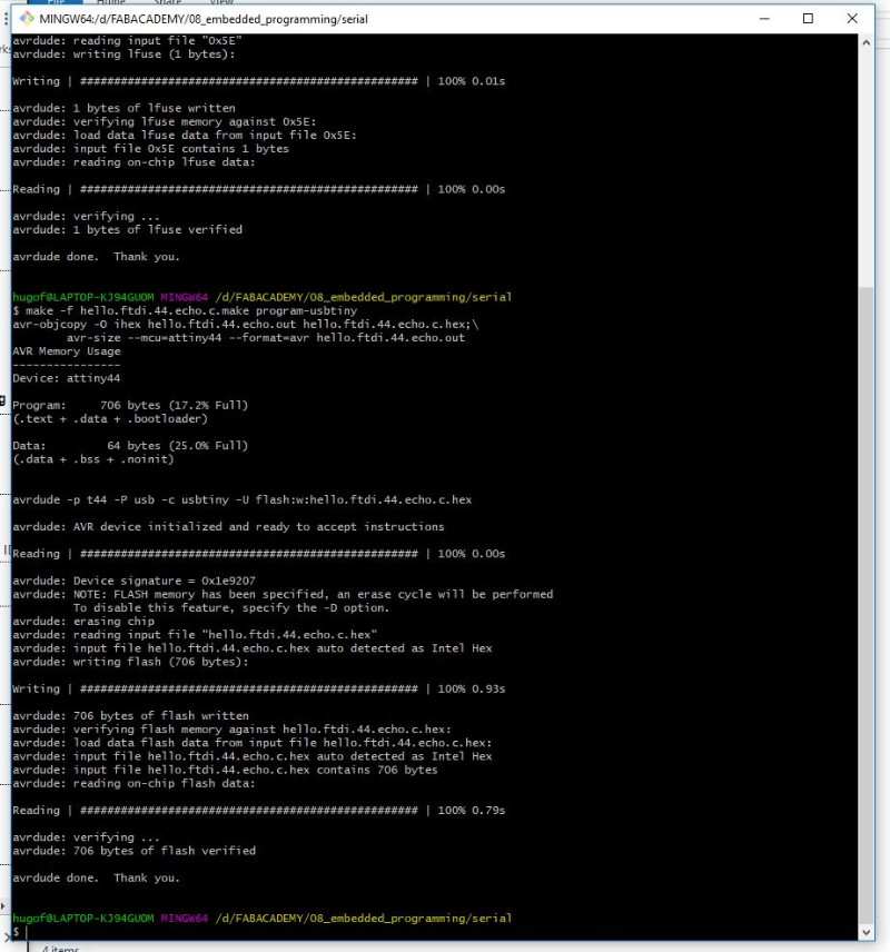
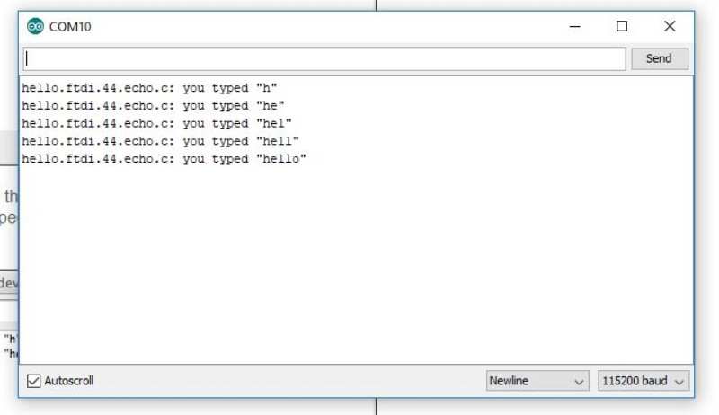
To see if everything worked and see the code in action you have to go back to Arduino IDE and open the Serial monitor (the icon at your right) and write something
During this assignment I didn't explore the full potential of programming, I learned more in the assignments that I did it after this one. That's why I have create this new section with links and examples of other codes that I used during fabacademy. More information about them can be found in the week were they've been develop.
Output Week. Charlieplexing code and tilt code.
I started with a base code for charlieplexing, it's not difficult but you have to take care with the order because each case it's prepare to turn on a different LED.
After this one I decided to turn the same board into a dize using a tilt sensor (almost a button) so I modified this code to work with it. It works, but i'm having some trouble to turn one more than one LED. I think that the reason it's in the delays
Watch more about this code in the OUTPUT WEEK
Final project.
In the final project I used to different boards, one for the input board ( a phototransistor) and another for the output (a stepmotor and 6 Neopixel). The board needed serial comunnication to send values from one to the other. Also, it's interesting how I needed to map values so the effect were really controlled.
This is the code for the input board.
This is the code for the outputboard
Watch more about this code in the PROJECT DEVELOPMENT WEEK or in the FINAL PAGE