Electronic Production
Some basic design rules were set out for us to follow and avoid discrepancies or failed milling operations. Firstly the Z- axis had to be zeroed as accurately as possible, using a multimeter to ensure exact contact with the PCB. Secondly, the PCB was to be fixed to the sacrificial layer using strong double faced tape to fix it in place.
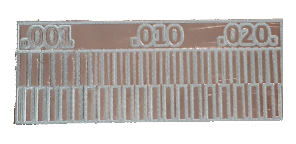
The image shown below is the resulting output for the calibration test. We can conclude that with these tools and settings we are able to achieve an accuracy of 0.007mm but with poor quality, the quality is acceptable starting at 0.008mm and onwards.