.png)
Hi! Welcome to Week 11
This week’s assignment was to measure something by add a sensor to a microcontroller board that I have designed and read it.
This week’s assignment was to measure something by add a sensor to a microcontroller board that I have designed and read it.
This week's assignment was going to be fairly simple. It will have several steps that are deciding which sensors to use, designing the board, and then programming the microcontroller.
After some thinking, I decided to build my own arduino board in order to use it for this week and next week's assignment for output devices. Since this was going to be an electronic design assignment, I headed back to Eagle and downloaded the Fab Library again in order to use the components assigned. I added it then by copying and pasting it in the Eagle folder on my laptop.
For more details on the designing process and how to use Eagle, you can refer to my electronics design week.
So the parts I added were:
1x ATmega 328p
1x 8MHz Resonater (instead of using a crystal and 2 capacitors)
1x FTDI
Pin Heads (lots of them, I connected almost all of the ports in order to take most advantage of them, I will be using few today and I'll save few for later). I also used to standard 2x3 pinheaders to be used when first programming the board.
and finally, I used 6x 0ohm resistors, in order to be used as jumpers ( I found out that I needed them later on when I started routing)
I conncted eash pin with its correspondent by assigning the same name to those conncted together, this is the diagram I ended with:
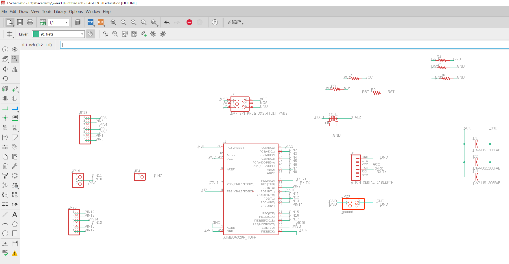
and you can download this schematic from here.
Next up, I started with the board routing, and this is when I knew I was going to need several jumpers, so I went back to the schematic and added them. I then played a little with the arrangemet and routes, and this was the result I got finally:
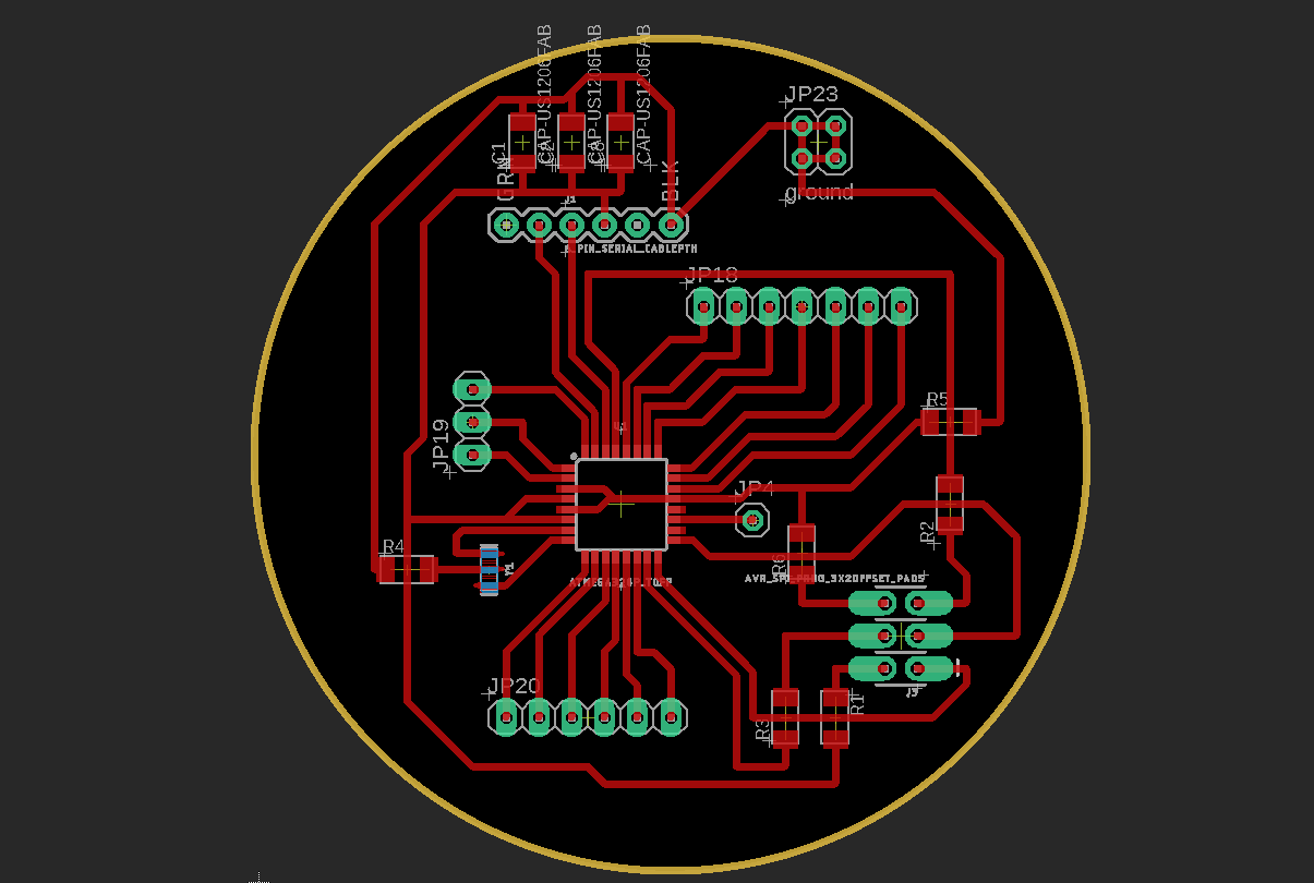
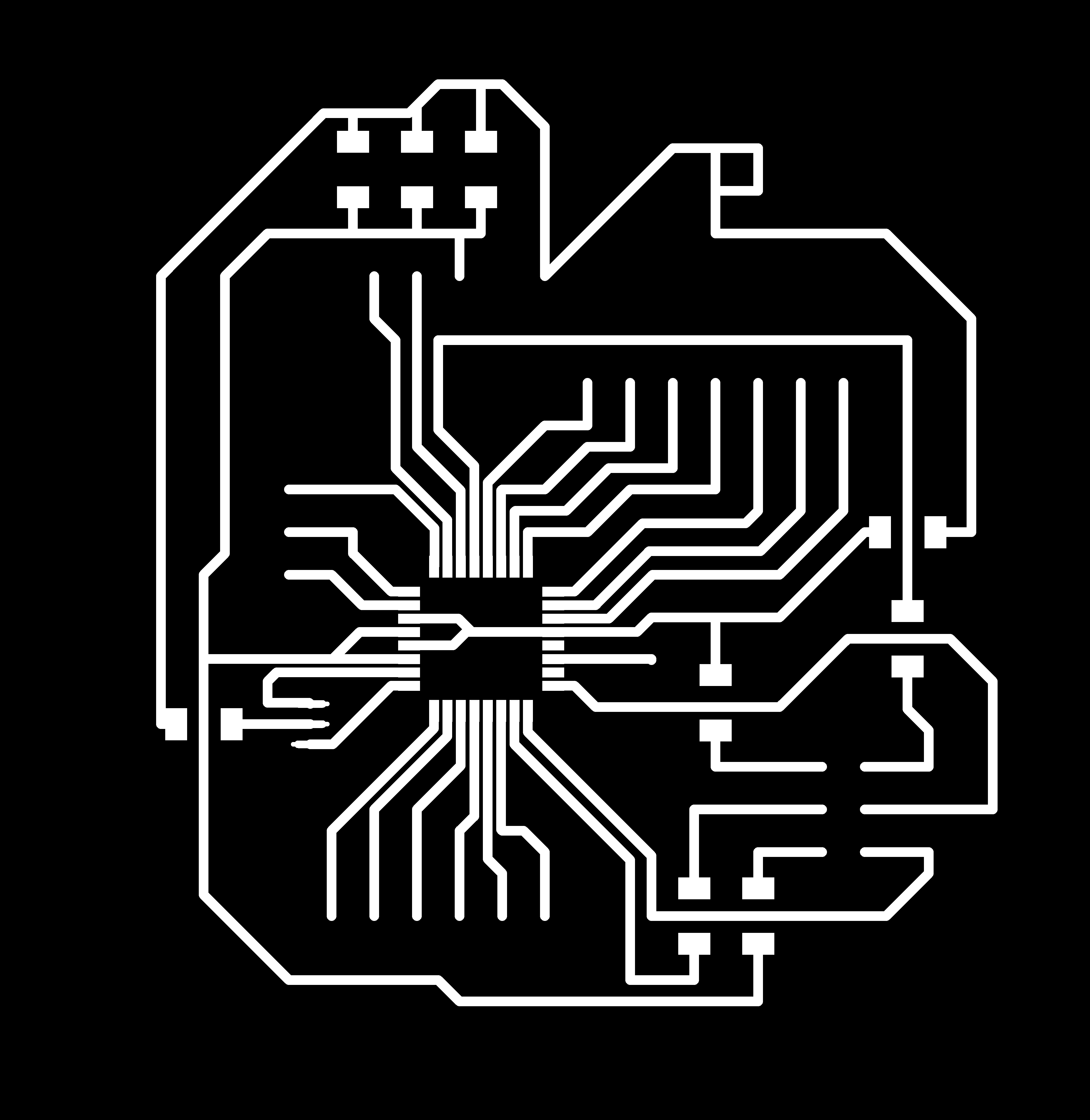
I exported the top layer (the one with traces), the outer line (the yellow one) and the holes separately, here they are:


And now that this part was ready, it was time for machining, I used the srm20 milling machine and FabModules. Preparing the order for the traces wasn't hard as I have done it before using the same settings in both the electronic production and electronics design weeks, you can download it from here.
A new thing I did for the first time this week was setting the order for the holes that will be cut, I used a 0.95 mm cutting tool, and the following settings:
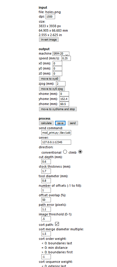
and you can download the order from here.
Next, I soldered the parts on the board, and then I proceeded to program it and that’s where I faced my problem. The board would be programmed just fine using Arduino as ISP, yet when I would link it to the computer using the FTDI to get the readings from the sensor printed on the serial monitor, it wouldn’t get programmed and I kept on getting an error message. During the review with the regional instructor Daniele Ingrassia, the error turned out to be that I forgot to add the reset switch and a 10k Ohm resistor. So I went back to make a new board, but since the board was working, I was to keep it for next week’s assignment as I won’t need a serial print.
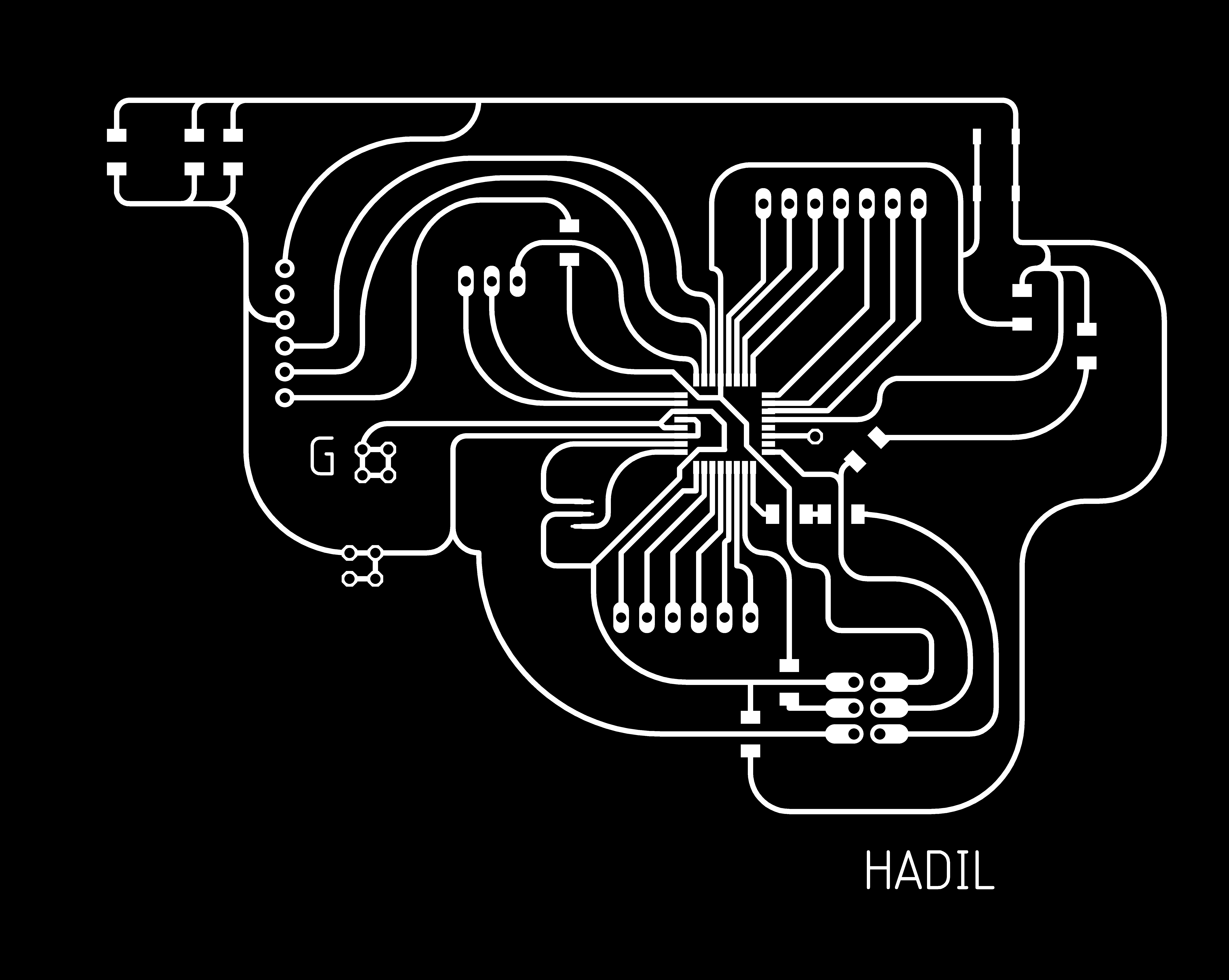
And so, I went back to eagle, edited the old schematic, I added the switch button that I linked to the GND and RST pins of the ATMega 328p. I also wanted to try something different with the looks of the board, and so I decided to make it look like a brain, and I was to use as many round curves as I could to give the same impression. This is my schematics, and the board design.
After I finished designing the board on Eagle, I imported the traces and holes as PNG images. As for the outer frame, I made a copy of the traces image, and then using CorelDraw, I drew the brains outline, before deleting the traces (I kept them in the beginning to make sure I won’t cut through one by mistake if I couldn’t see them). Here are the traces, holes, and the outline.


Now, I cut the board on the SRM-20 milling machine. For more details on how to use it you can refer to electronics production week. These are my cutting files:
traces, holes, and the outline.
Next, I soldered the parts again to the board, and proceeded to program it, where –again- I faced some problems. The first problem was that although the board burned the bootloader, it would get programmed yet it doesn’t do the program (no power was delivered to the pin in the program).I used a simple program just to check if everything was working, a blinking LED that still didn’t work. I triple checked the connections and all and nothing seemed off. After several round of trying to trouble shoot, I finally settled on changing the microchip and using a new one as I thought I might have burned it using too much heat for longer than I should while soldering. During my removal of the old ATmega 328p, I accidently removed few traces, so I faced few challenges when I tried to solder the new microchip, I had to make extensions using copper wires, and soldered the sides to the microchip and the trace. I found it very hard to avoid connecting 2 paths by mistake while making sure that the solder head doesn’t touch the legs of the microchip for a long time. I finished this step and when I went back to program it, I was surprised that it wouldn’t even burn the bootloader! Why? Turns out I have been soldering the ATmega U instead of ATmega328p. I took a look at the datasheet of each one, and the pinout was different, and so I – again- had to remove the microchip and solder a new one. By now I got used to it, and instead of removing each leg solo using a solder head and a pick, I learned a new technique using a heat gun, and so no damage was done other than the one from the first time. After soldering the new one, the board did burn the bootloader, and be programmed, yet no power was delivered to the LED.
After A LOT of time spent, I finally came to realize that the switch button should have been also linked to the VCC, and all the steps before weren’t needed. And so I added a 10K Ohm resistor, linked it to the RST and to the VCC, and voilaaa! The reset button worked, the program worked, the LED lit, and it finally seemed to go smoothly.
The reason for that could be explained with "nothing doesn't mean zero". I had to prevent the nosie from getting to the RST, and by connecting the 10K resistor to the VCC, I was maintaining the working mode (5V) when it's working (pull-up).
I then prepared the following program that I edited a bit:
Download this code from here.
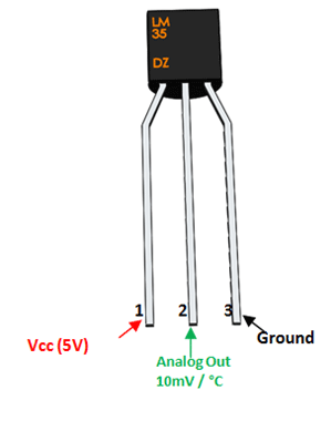
With this code, I used an LM35 Temperature Sensor, you can check its data sheet. the temperature sensores work by varying their output voltage, based on the temperature around it. In real life, temp. sensors have many applications, like easuring temperature of a particular environment, providing thermal shutdown for a circuit/component, and monitoring battery Tteperature. The pinout of the sensore I used is as follows:
      /*Code designed by Sujay Alaspure in SA Lab */
const int sensor=A2; // Assigning analog pin A7 to variable 'sensor'
const int LED=4;
float tempc; //variable to store temperature in degree Celsius
float vout; //temporary variable to hold sensor reading

void setup() {
pinMode(sensor,INPUT); // Configuring sensor pin as input
  pinMode(LED, OUTPUT);
}

void loop() {
vout=analogRead(sensor); //Reading the value from sensor
vout=(vout*500)/1023;
tempc=vout; // Storing value in Degree Celsius

if (tempc > 27)
{
 digitalWrite(LED, HIGH);  // turn the LED on (HIGH is the voltage level)
}
else {
  digitalWrite(LED, LOW);    // turn the LED off by making the voltage LOW}
}
}