.png)
Hi! Welcome to Week 14
This week’s assignment was to design, build, and connect wired or wireless node(s) with network or bus addresses.
This week’s assignment was to design, build, and connect wired or wireless node(s) with network or bus addresses.
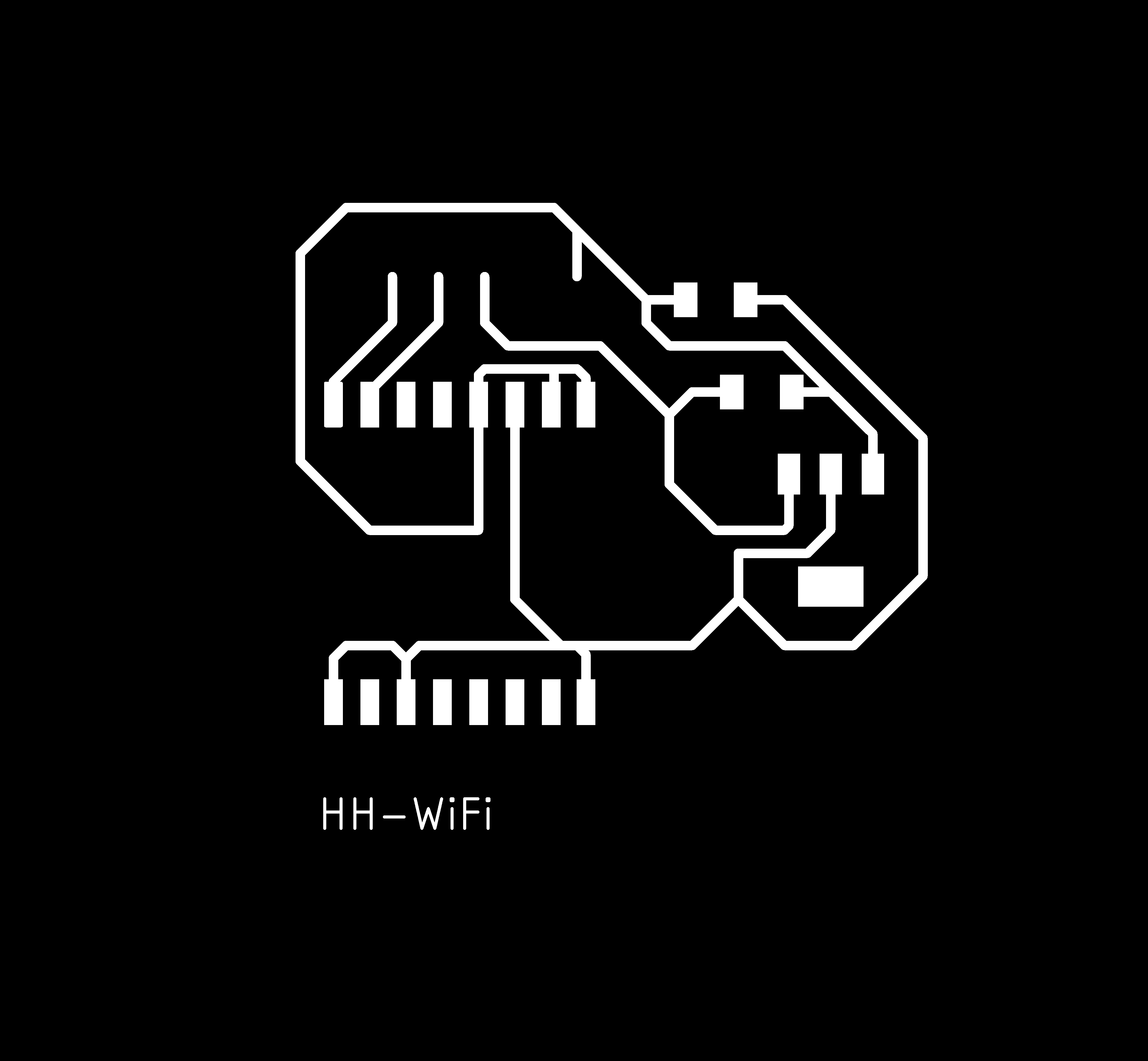
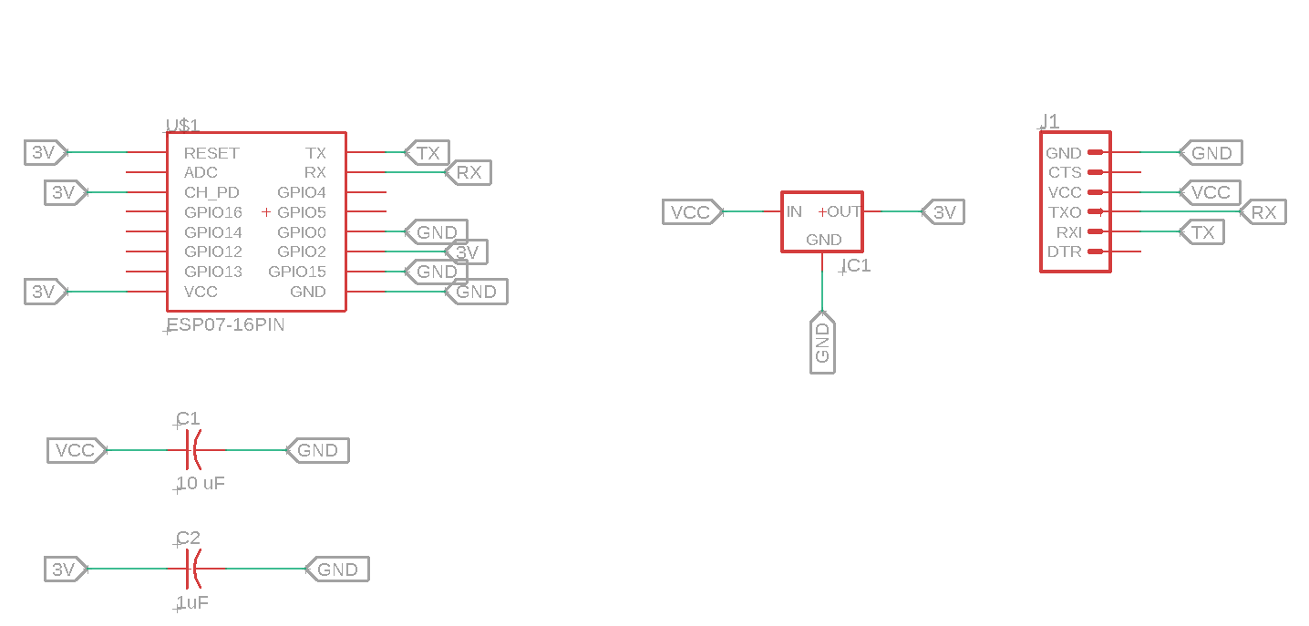
I started this week with the WiFi, I designed my board according to the designs of the previous students in FabAcademy using EAGLE software. For the components, I used:
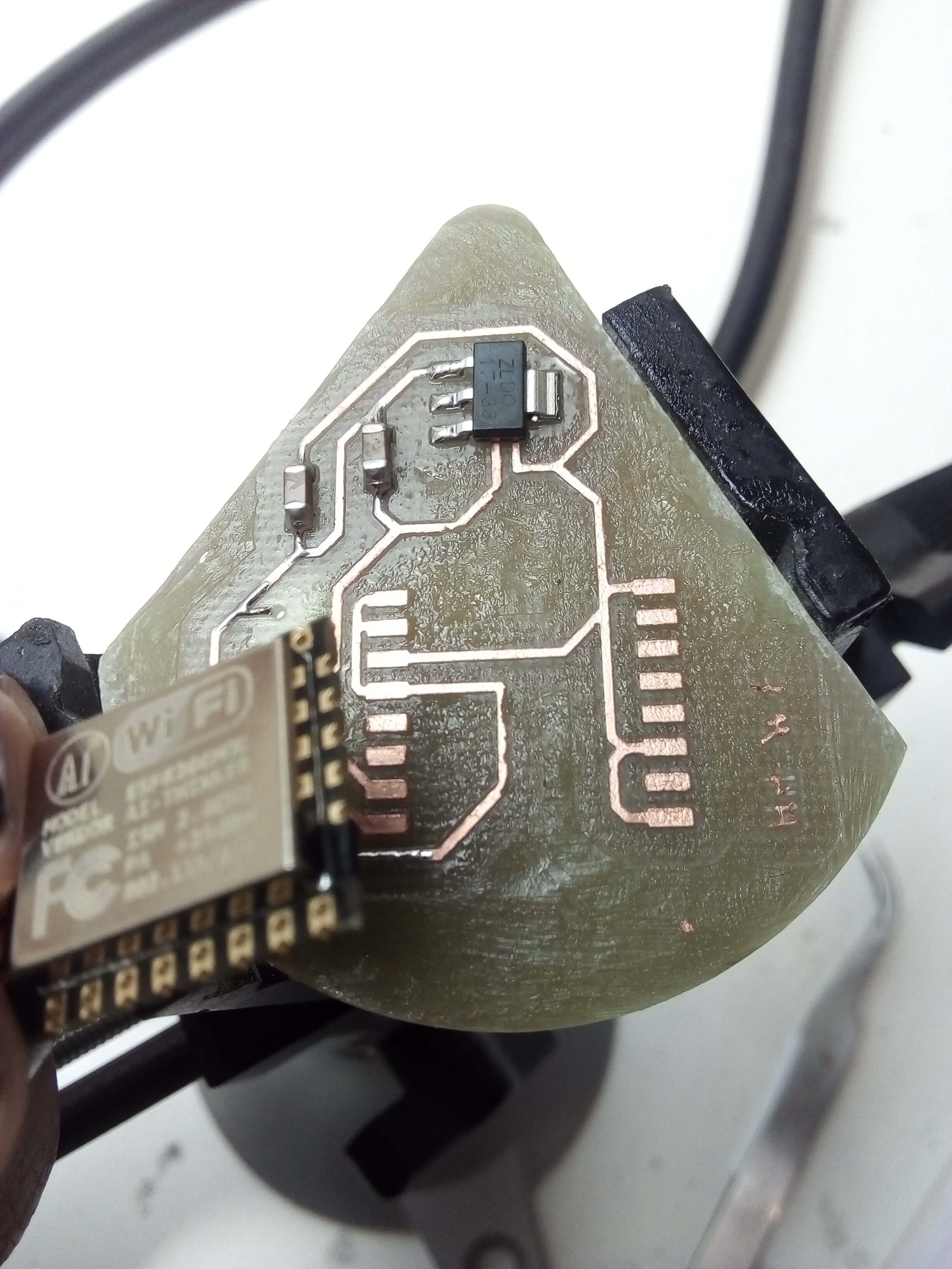
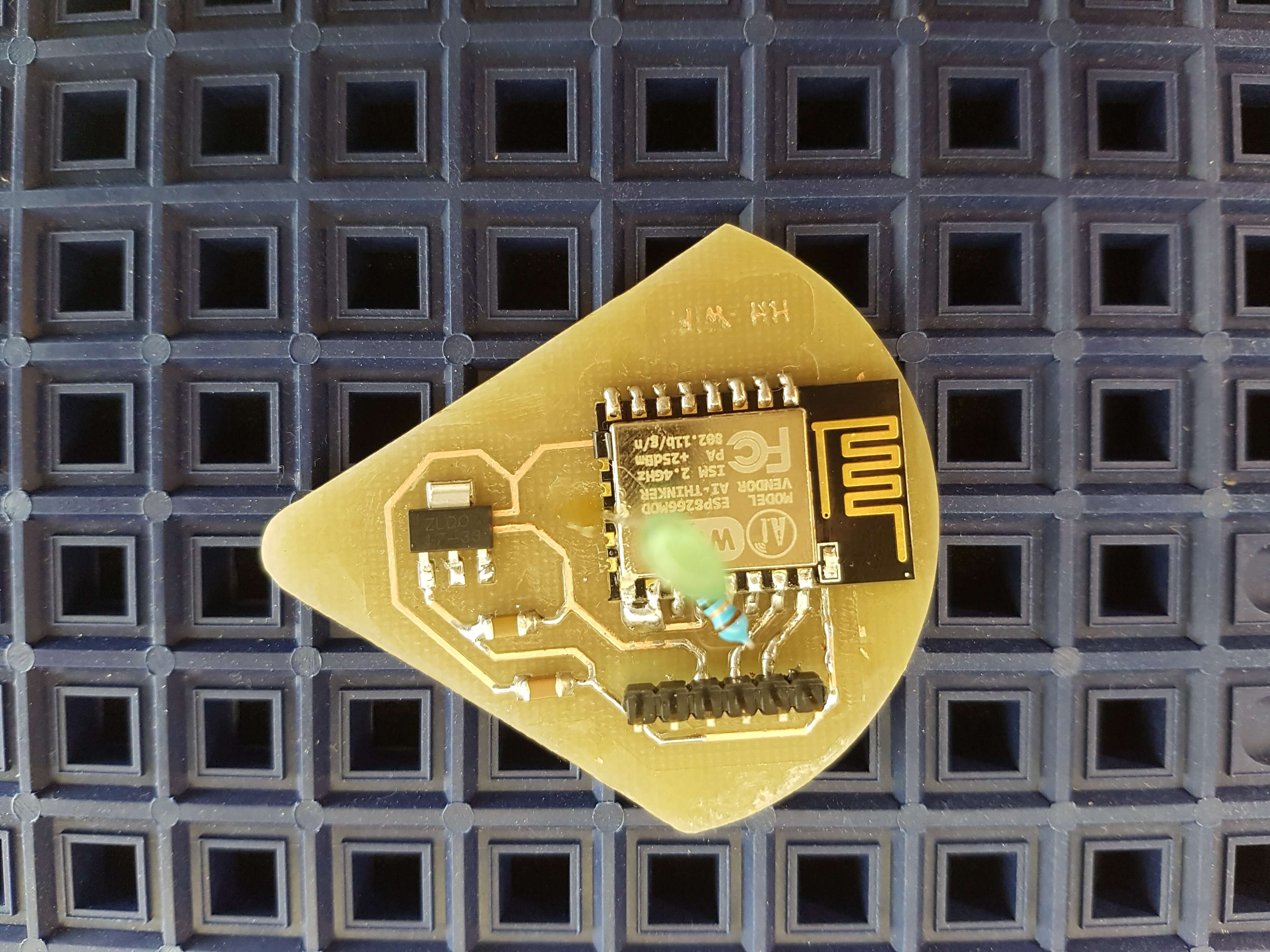
1*ESP8266 12E Module (in the schematics and board, I used ESP07 module, but it was out from the lab so I then used the ESP8266 12E Module as it turned out to have the same dimensions of pins with the exception of one extra side)
1*3.3V voltage regulator
( Because from the data sheet of the ESO module ot stated that it operates on 3.3V)
1*FTDI Header (6*Pin headers)
1*1 uF Capacitor 1 uF
1*10 uF Capacitor


To understand where each component should take place, I checked the datasheet from here. I also found this pinout of the module which helped alot.
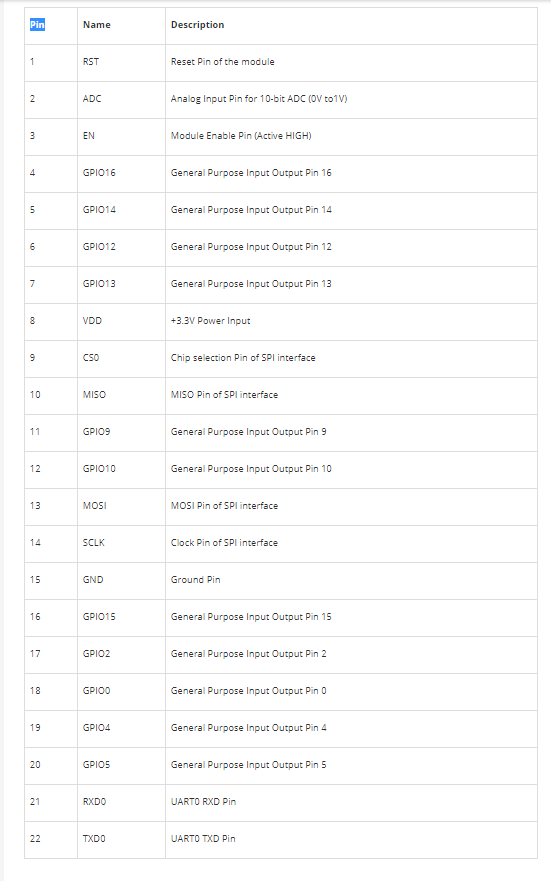

and based on that I connected the schematics as follows: The GNDs, 3Vs, TX and RX.
Download the schematics from here, the board from here, or click on any of the images above to download it.
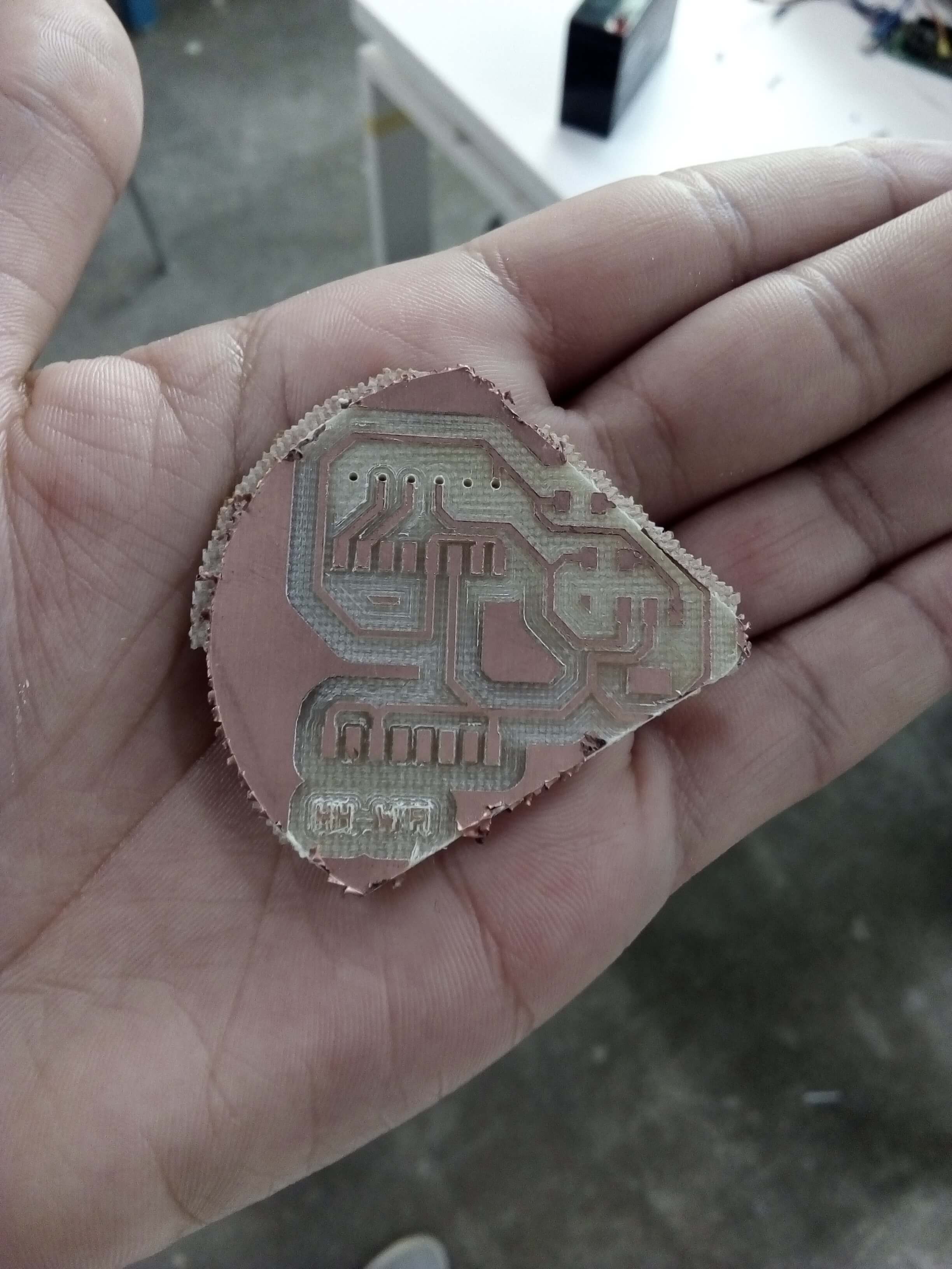
Next, I started soldered the components.
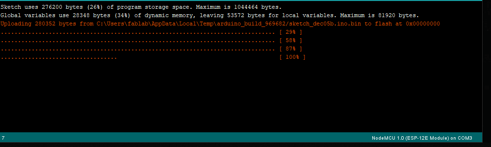
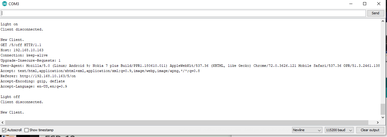
And it was ready for programming :D it was easily programmed using the FTDI cable on Arduino, but I had a problem in uploading the program. I spent hours and hours, in the end, the problem was with the computer I was using, I switch to another PC and it uploaded right away. At first, I uploaded an empty program to check the board. I then uploaded a program that would allow me to light an LED on and off, uploaded it and then checked with the multimeter if there was voltage getting to the pin GPIO10, it did. So since I didn’t have an LED on the board when I milled it, I added and LED and an 82 Ohm Resistor to the board, linked it to pin GPIO10 and GND. I then uploaded the program again just to double check, opened the serial monitor, and after few seconds I got the information I wanted on the SM. You can download the program from here.
// Load Wi-Fi library
#include <ESP8266WiFi.h>

// Replace with your network credentials
const char* ssid     = "LTUC_Guests";
const char* password = "123456789";

// Set web server port number to 80
WiFiServer server(80);

// Variable to store the HTTP request
String header;

// Auxiliar variables to store the current output state
String output5State = "off";
String output4State = "off";

// Assign output variables to GPIO pins
#define output5 10


void setup() {
  Serial.begin(115200);
  // Initialize the output variables as outputs
  pinMode(output5, OUTPUT);


  // Set outputs to LOW
  digitalWrite(output5, LOW);


  // Connect to Wi-Fi network with SSID and password
  Serial.print("Connecting to ");
  Serial.println(ssid);
  WiFi.begin(ssid, password);
  while (WiFi.status() != WL_CONNECTED) {
    delay(500);
    Serial.print(".");
  }
  // Print local IP address and start web server
  Serial.println("");
  Serial.println("WiFi connected.");
  Serial.println("IP address: ");
  Serial.println(WiFi.localIP());
  server.begin();
}

void loop(){
  WiFiClient client = server.available();   // Listen for incoming clients

  if (client) {                             // If a new client connects,
    Serial.println("New Client.");          // print a message out in the serial port
    String currentLine = "";                // make a String to hold incoming data from the client
    while (client.connected()) {            // loop while the client's connected
      if (client.available()) {             // if there's bytes to read from the client,
        char c = client.read();             // read a byte, then
        Serial.write(c);                    // print it out the serial monitor
        header += c;
        if (c == '\n') {                    // if the byte is a newline character
          // if the current line is blank, you got two newline characters in a row.
          // that's the end of the client HTTP request, so send a response:
          if (currentLine.length() == 0) {
            // HTTP headers always start with a response code (e.g. HTTP/1.1 200 OK)
            // and a content-type so the client knows what's coming, then a blank line:
            client.println("HTTP/1.1 200 OK");
            client.println("Content-type:text/html");
            client.println("Connection: close");
            client.println();

            // turns the GPIOs on and off
            if (header.indexOf("GET /5/on") >= 0) {
              Serial.println("Light on");
              output5State = "on";
              digitalWrite(output5, HIGH);
            } else if (header.indexOf("GET /5/off") >= 0) {
              Serial.println("Light off");
              output5State = "off";
              digitalWrite(output5, LOW);
            }

            // Display the HTML web page
            client.println("<html>");
            client.println("<head><meta name=\"viewport\" content=\"width=device-width, initial-scale=1\">");
            client.println("<link rel=\"icon\" href=\"data:,\">");
            // CSS to style the on/off buttons
            // Feel free to change the background-color and font-size attributes to fit your preferences
            client.println("<style>html { font-family: Helvetica; display: inline-block; margin: 0px auto; text-align: center;}");
            client.println(".button { background-color: #195B6A; border: none; color: white; padding: 16px 40px;");
            client.println("text-decoration: none; font-size: 30px; margin: 2px; cursor: pointer;}");
            client.println(".button2 {background-color: #77878A;}</style></head>");

            // Web Page Heading
            client.println("<body><h1>ESP8266 Web Server</h1>");

            // Display current state, and ON/OFF buttons for GPIO 5
            client.println("<p>Light - State " + output5State + "</p>");
            // If the output5State is off, it displays the ON button
            if (output5State=="off") {
              client.println("<p><a href=\"/5/on\"><button class=\"button\">ON</button></a></p>");
            } else {
              client.println("<p><a href=\"/5/off\"><button class=\"button button2\">OFF</button></a></p>");
            }


            // Break out of the while loop
            break;
          }else { // if you got a newline, then clear currentLine
            currentLine = "";
          }
        } else if (c != '\r') {  // if you got anything else but a carriage return character,
          currentLine += c;      // add it to the end of the currentLine
        }
      }
    }
    // Clear the header variable
    header = "";
    // Close the connection
    client.stop();
    Serial.println("Client disconnected.");
    Serial.println("");
  }
}
/*
  Software serial multiple serial test

 Receives from the hardware serial, sends to software serial.
 Receives from software serial, sends to hardware serial.

 The circuit:
 * RX is digital pin 10 (connect to TX of other device)
 * TX is digital pin 11 (connect to RX of other device)

 Note:
 Not all pins on the Mega and Mega 2560 support change interrupts,
 so only the following can be used for RX:
 10, 11, 12, 13, 50, 51, 52, 53, 62, 63, 64, 65, 66, 67, 68, 69

 Not all pins on the Leonardo and Micro support change interrupts,
 so only the following can be used for RX:
 8, 9, 10, 11, 14 (MISO), 15 (SCK), 16 (MOSI).

 created back in the mists of time
 modified 25 May 2012
 by Tom Igoe
 based on Mikal Hart's example

 This example code is in the public domain.

 */
#include   <SoftwareSerial.h>

SoftwareSerial mySerial(11, 12); // RX, TX

void setup() {
  // Open serial communications and wait for port to open:
  Serial.begin(9600);
  while (!Serial) {
    ; // wait for serial port to connect. Needed for native USB port only
  }


  Serial.println("Goodnight moon!");

  // set the data rate for the SoftwareSerial port
  mySerial.begin(9600);
  mySerial.println("Hello, world?");
}

void loop() { // run over and over
  if (mySerial.available()) {
    Serial.write(mySerial.read());
  }
  if (Serial.available()) {
    mySerial.write(Serial.read());
  }
}
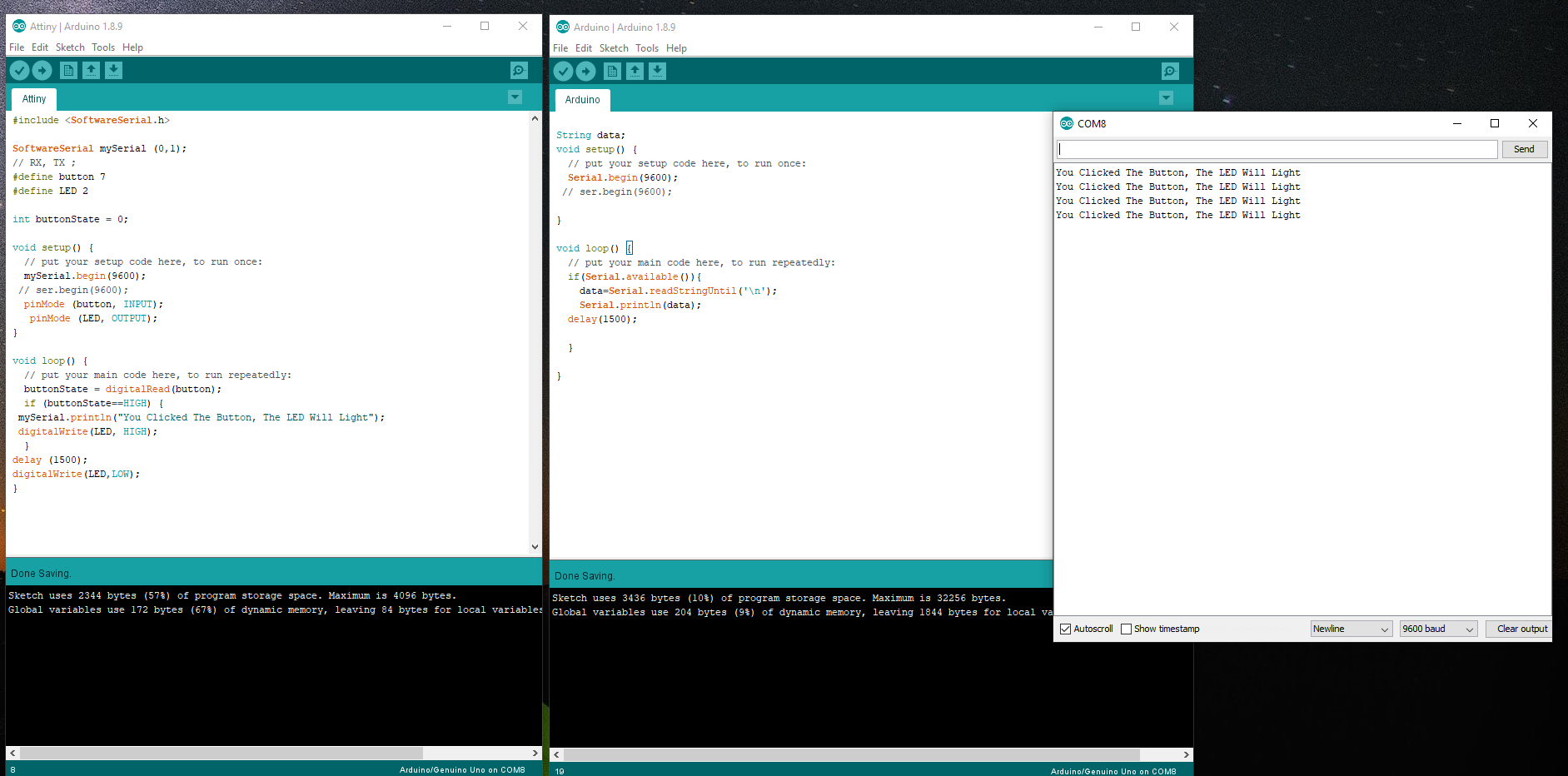
#include  <SoftwareSerial.h>

SoftwareSerial mySerial (0,1);
// RX, TX ;
#define button 7
#define LED 2

int buttonState = 0;

void setup() {
  // put your setup code here, to run once:
  mySerial.begin(9600);
 // ser.begin(9600);
  pinMode (button, INPUT);
   pinMode (LED, OUTPUT);
}

void loop() {
  // put your main code here, to run repeatedly:
  buttonState = digitalRead(button);
  if (buttonState==HIGH) {
 mySerial.println("You Clicked The Button, The LED Will Light");
 digitalWrite(LED, HIGH);
  }
delay (1500);
digitalWrite(LED,LOW);
}
String data;
void setup() {
  // put your setup code here, to run once:
  Serial.begin(9600);
 // ser.begin(9600);

}

void loop() {
  // put your main code here, to run repeatedly:
  if(Serial.available()){
    data=Serial.readStringUntil('\n');
    Serial.println(data);
  delay(1500);

  }

}
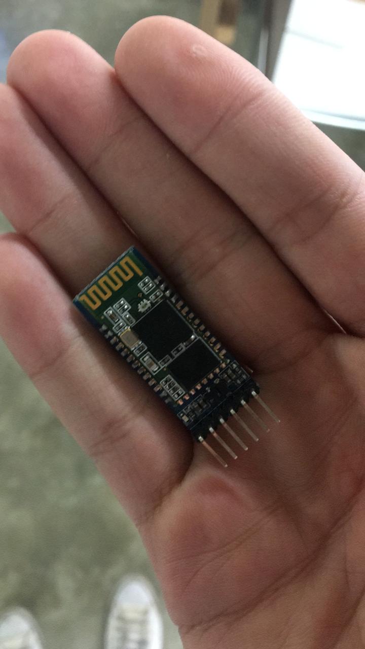
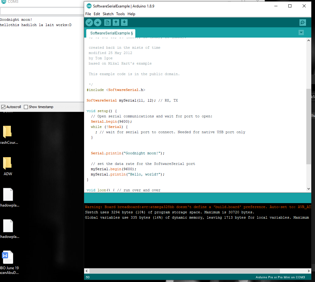
And Then I opened the serial monitor, and it showed nothing :D fortunately, the problem was that I had chosen the wrong baud rate, after changing it in the beginning it started giving reading that was gibberish I tried several rates till I found the one that worked perfectly.