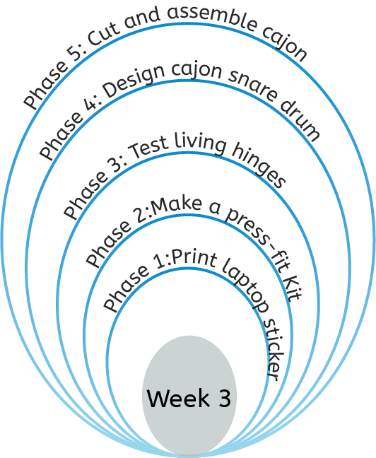
This week is focused on computer controlled cutting. This is usually in 2D, not considering engraving or taking into accound rotary laser cutters. I set up a clamshell development plan for this week, shown below. I wanted to ultimately achieve four things this week, covering 5 concepts in computer controlled cutting. My initial goal was to create a press-fit kit which can be made into various objects, a vinyl sticker and test out living hinges. If all of the three tasks were completed, I was to move on to making a Cajon snare drum. The design I had in mind included several concepts and would provide a chance for me to practice these techniques. Ofcourse, the group task was a requirement and was considered as a parallel task.
Group task: Measuring the kerf
For the group task we measured the kerf of various materials and thicknesses. We used two different methods; Firstly, a comb with varying incrementally decreasing tooth width and secondly, a block cut into ten pieces measuring the decrease in size. The materials we used were MDF, cardboard, Acrylic and plywood.
Vinyl Printing/Cutting
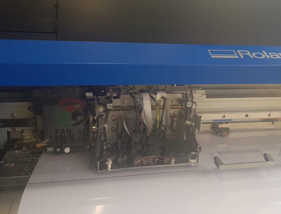
For Vinyl printing and cutting I was using the Roland vinyl cutting machine available in the lab. In order to ready the caterpillar sticker design created last week, I had to make sure the colors were correct then create a cutting outline. I used Adobe Illustrator, hoever I first had to install the Roland Versaworks Swatch library for the cutting path. I found the swatch library through a simple google search on . After downloading the library, I simply copied it to Library/ApplicationsSupport/Adobe/Adobe Illustrator CC 2017/Preset/en_GB/Swatch / as instructed. Note: I have a Mac... The location is different for Windows machines.
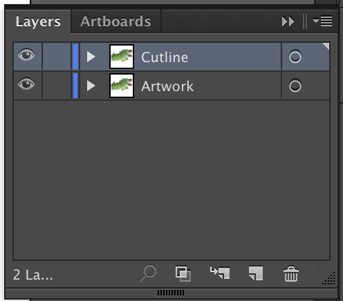
Check that the document colors are in CMYK, since the printers in general use the CMYK color palette. The first step in processing the design was to create two copies, each in a seperate layer. Label one layer for the cutting path and the other for printing.
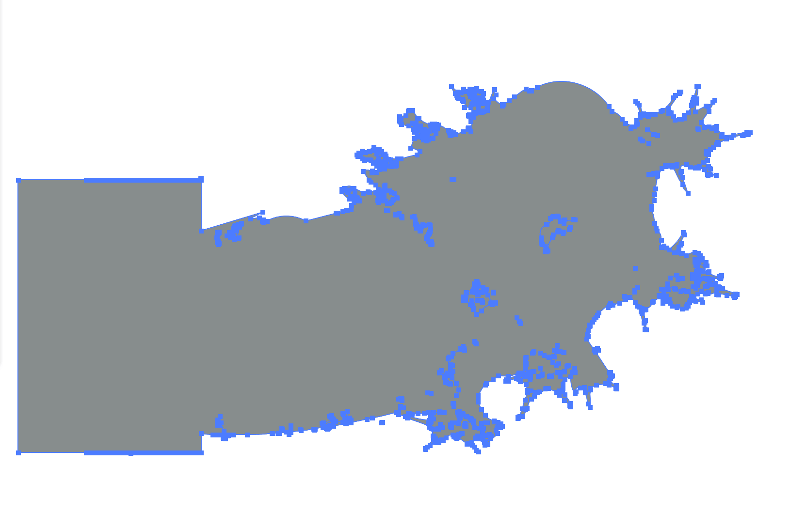
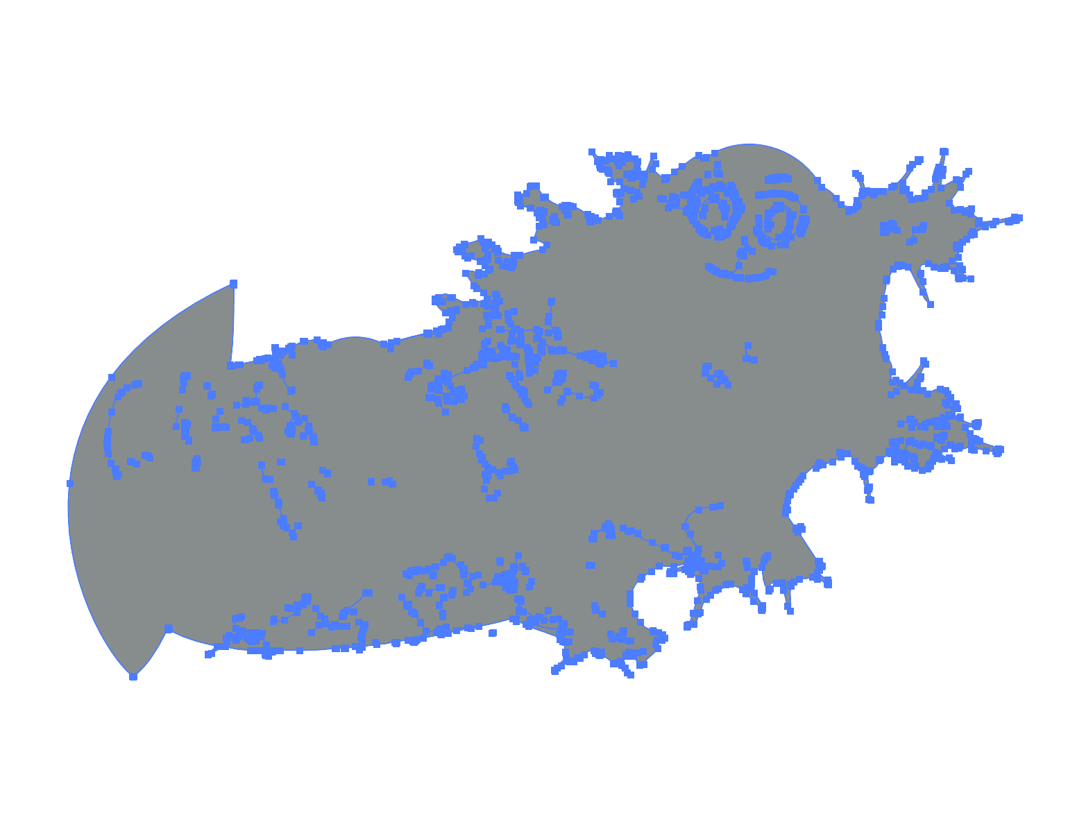
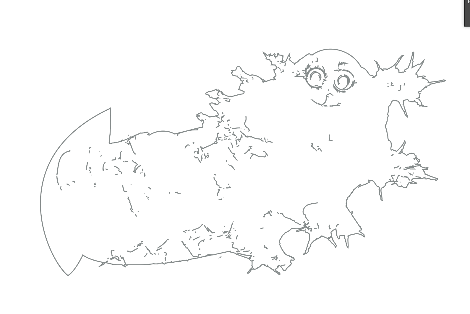
Next I selected the design and used pathfinder tool in illustrator to find the outline. As can be seen in the first image, Illustrator didn't select the desire outline, so I had to merge the components of the design and try again. The second result worked and rendered the desired outline.
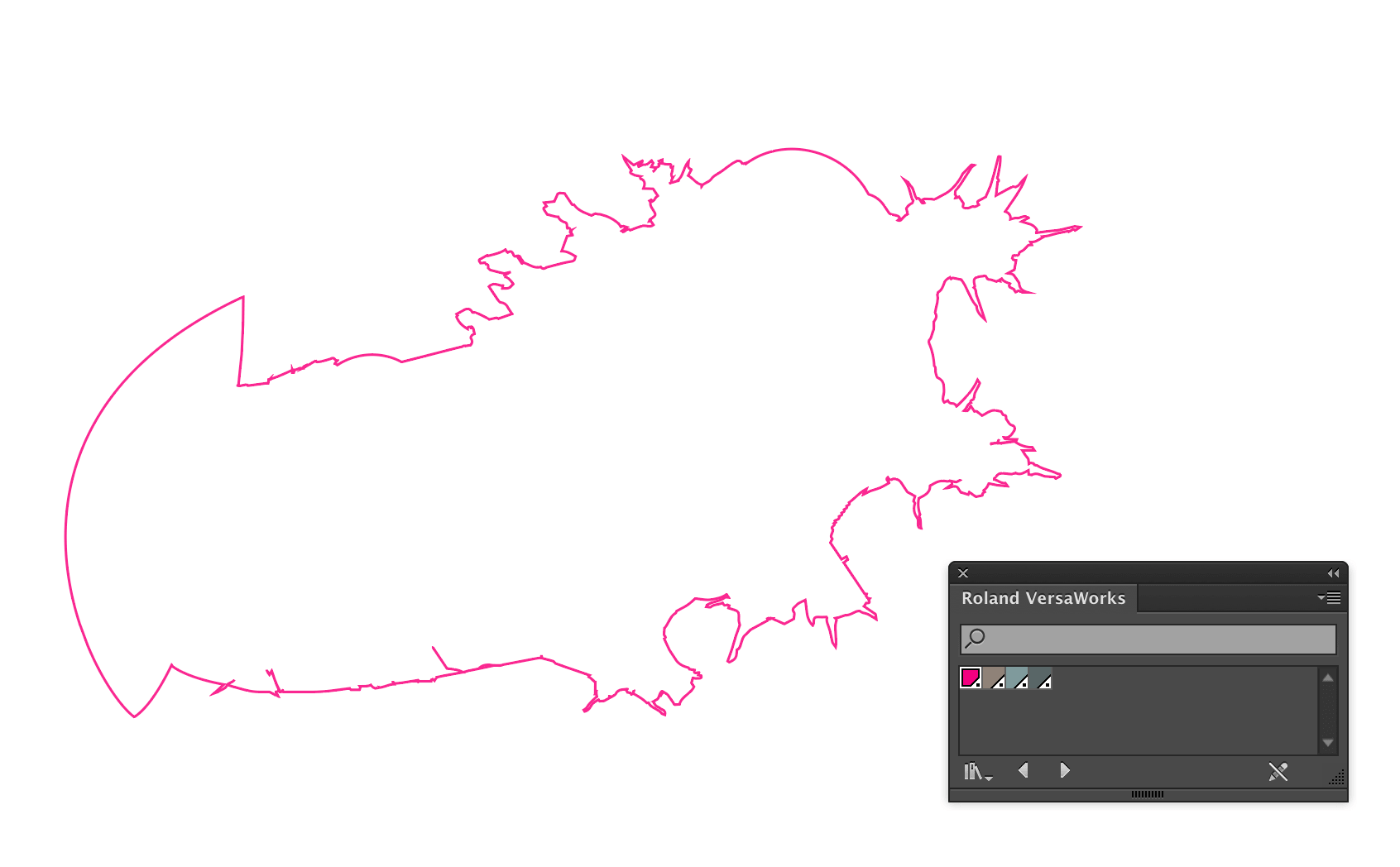
Then I changed the fill to white and continued cleaning up any details picked up by illustrator inside the shape's design. Lastly I selected the outline color and used the installed Roland Versaworks swatch to set it as a cut contour. The cutting layer, shown on the right was now also ready.
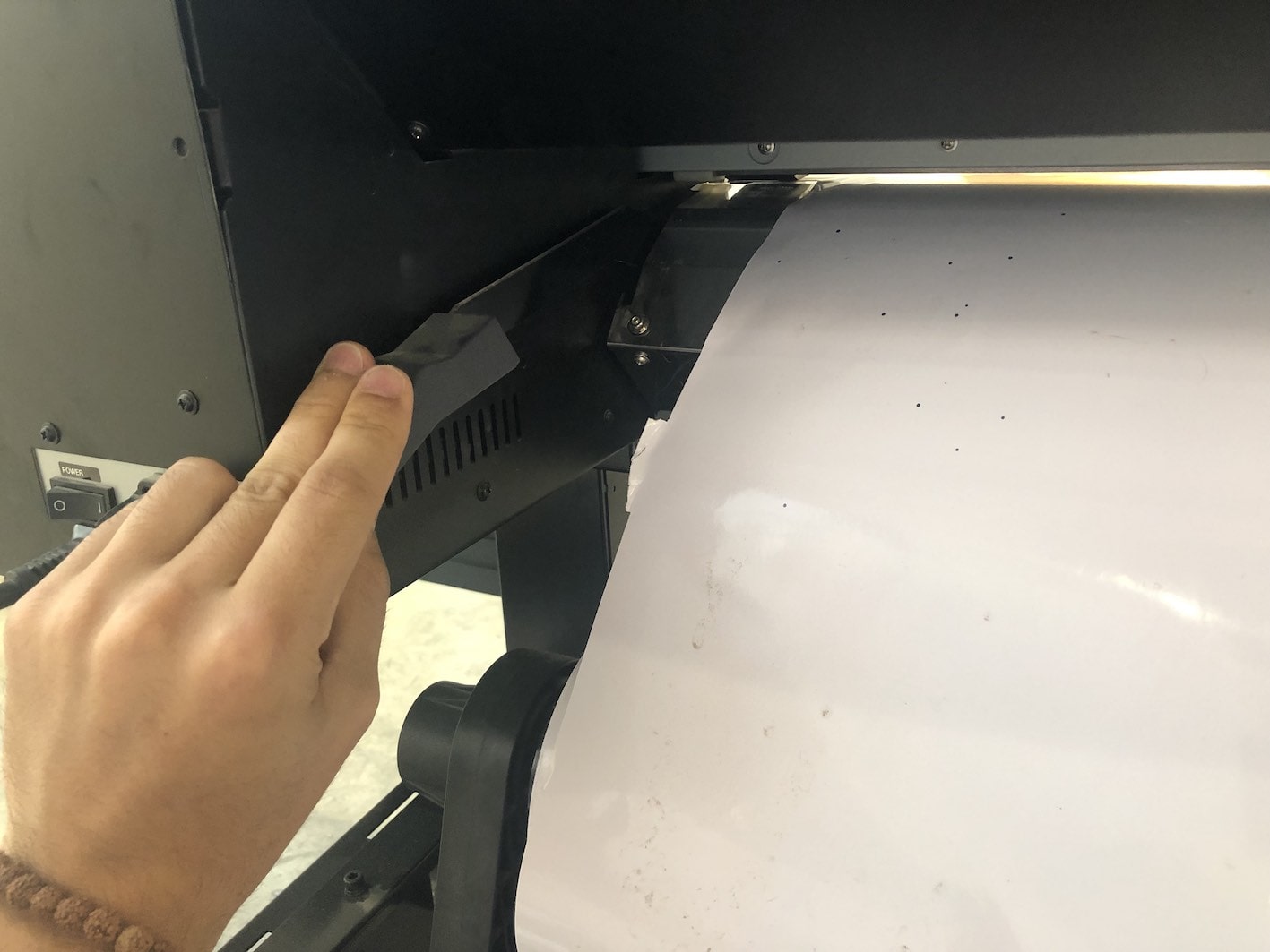
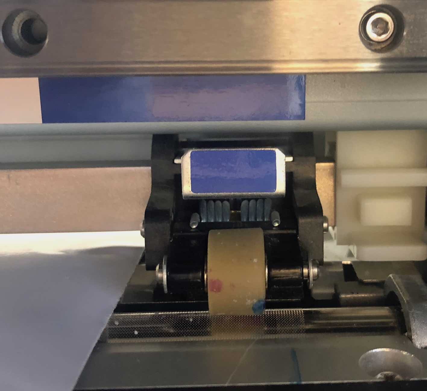
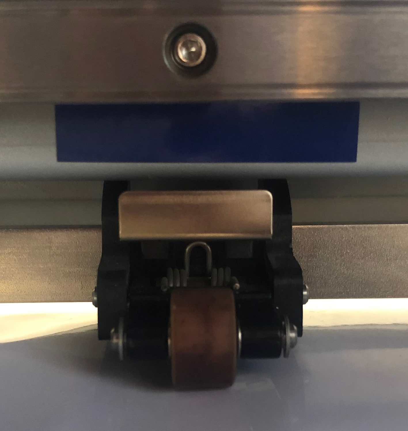
I loaded the white vinyl into the machine by lifting the locking handle and sliding the new roll through the machine, then pulling the handle back down to lock. This can be done from the front or back of the machine, since there are two identical handles on both sides. Then, I made sure the primary rollers were on their respective blue positions, to indicate the width of the vinyl sheet, while the normal rollers are inserted in the middle primarily for smoother rolling and stability. All rollers must be within the marked roller placements.
Sheet lock handle
Edge roller (marked blue)
Mid roller (unmarked)
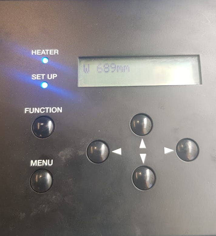
Then the machine automatically measures the length of the cutting/printing area according to the placement of the rollers. This is done when the front cover is closed, afterwhich the sensors on printing head survey the width by moving along the axis of the machine and dedtecting the rollers, the width will be displayed on the on-board display.
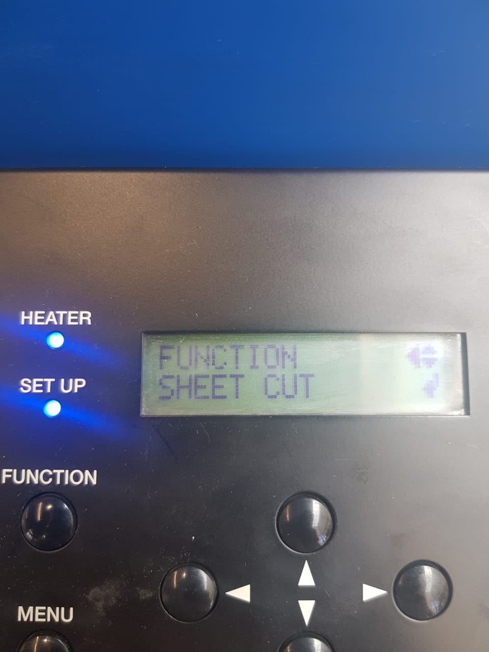
Then using the machine's display, there is an option that can be navigated to from the main menu called sheetcut which allows you to cut the edge of the sheet manually. I did this since the edge wasn't smooth.
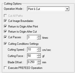
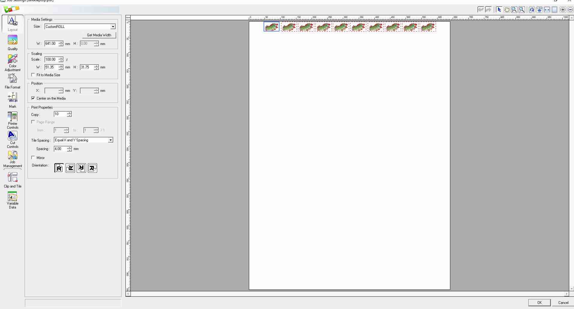
After the vinyl sheet was loaded, I loaded the design file shown below into the Roland Versaworks program. In the layout settings I set it to 10 copies and centered them on the media. For the print and cut options, I used the settings below. I set the cut passes to 3 to make sure it cuts through and checked cut image boundaries which cut an additional square around the stickers. As displayed in the screenshots below this is specified from the cut control and layout menus.
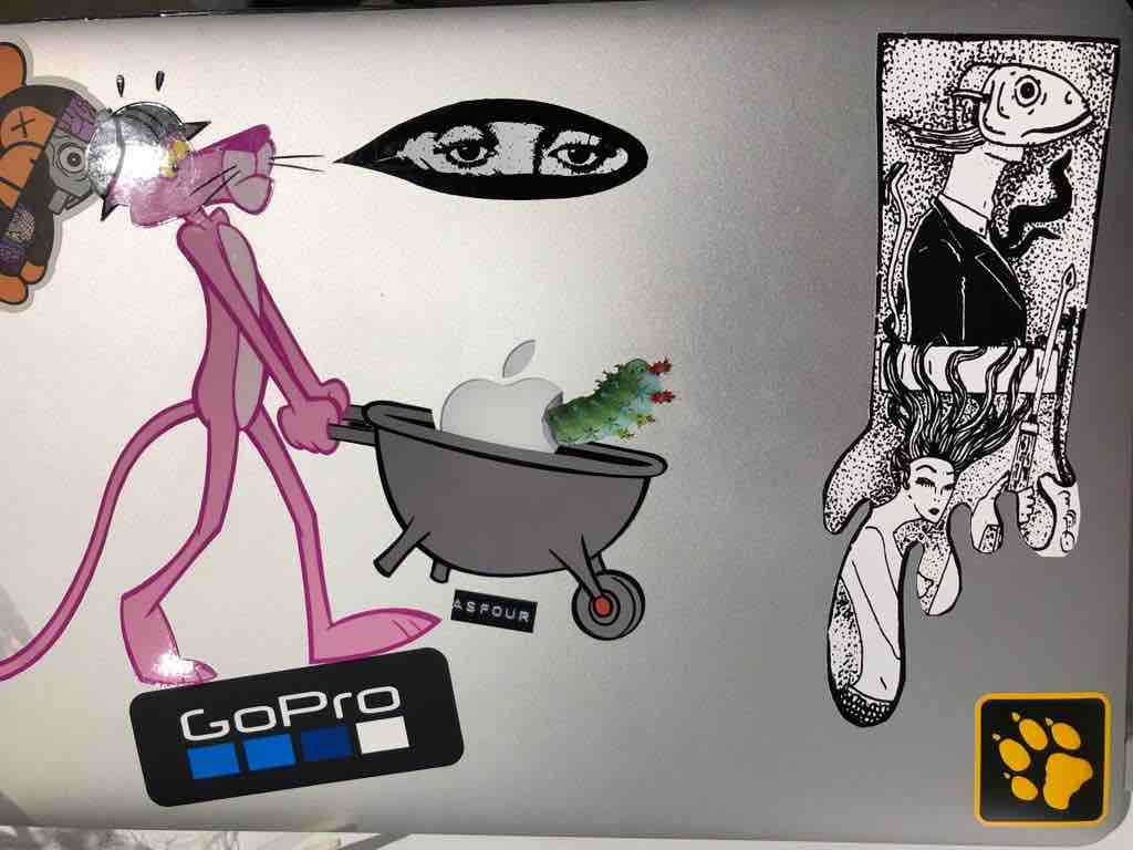
Everything worked fine and the resulting print fit perfectly on my Macbook
Press-fit Kit
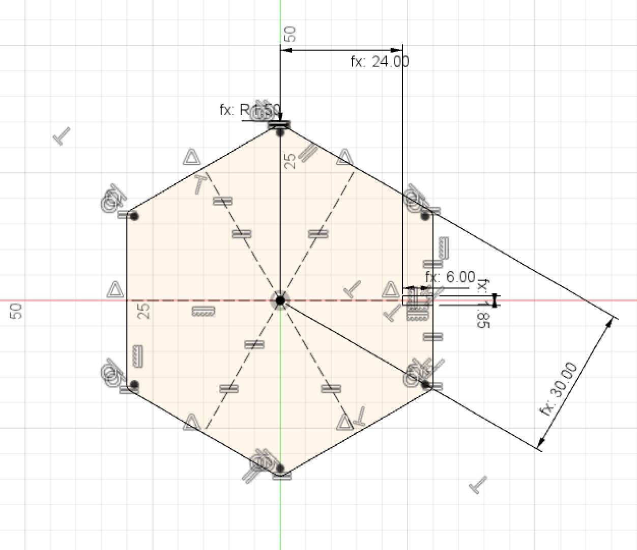
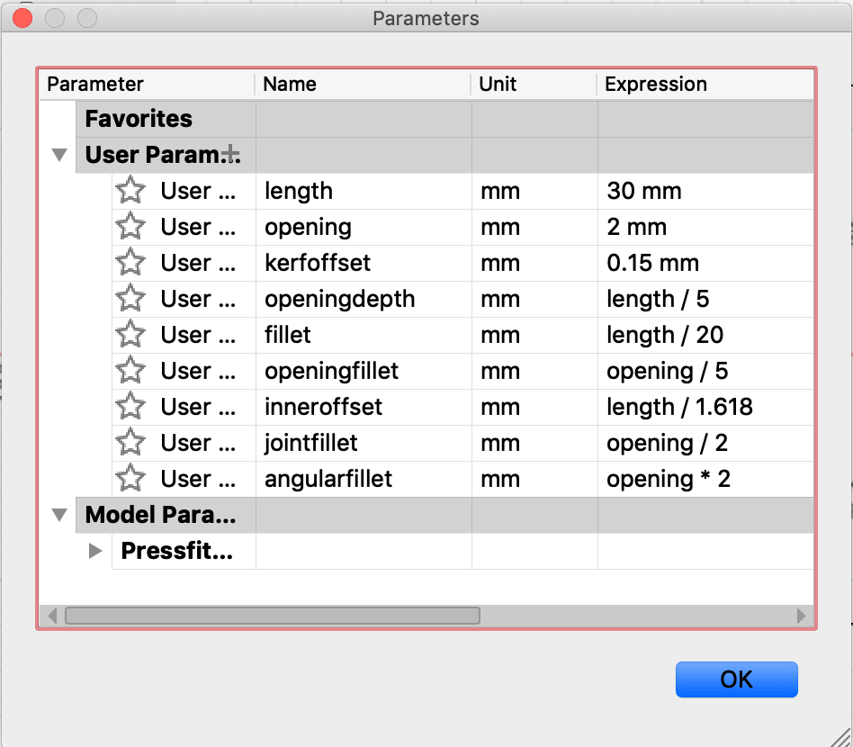
The press-fit kit I wanted to design was a parametric hexagonal kit based on one piece and a few joints with varying angles. I later cut out a piece with a different inner shape to be able to hold a lightbulb fixture. The goal of the press-kit was experimentation and developing new ideas and additions to the kit. First and foremost, I designed the main hexagonal piece. I used constraints on Fusion to relate dimensions of the shape to each other and fix them to the sketch plane. The dimensions were all set as user parameters in the parametric window and and most were mathematically based on the length of the hexagon or the thickness of the material (specified as opening). The kerf was a parameter and subtracted from the opening when specifying the dimensions.
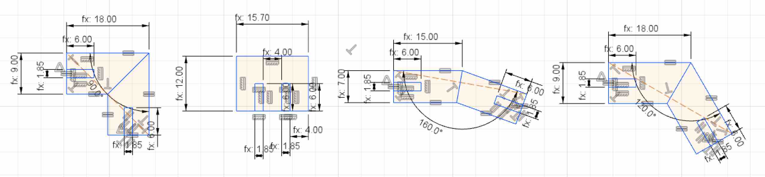
After designing the main piece, I went on to create a template for angular joints, to start with I created two and then added another two with (180, 160, 120, 90) degrees respectively. The joints were also parametric and linked to the design of the main piece.
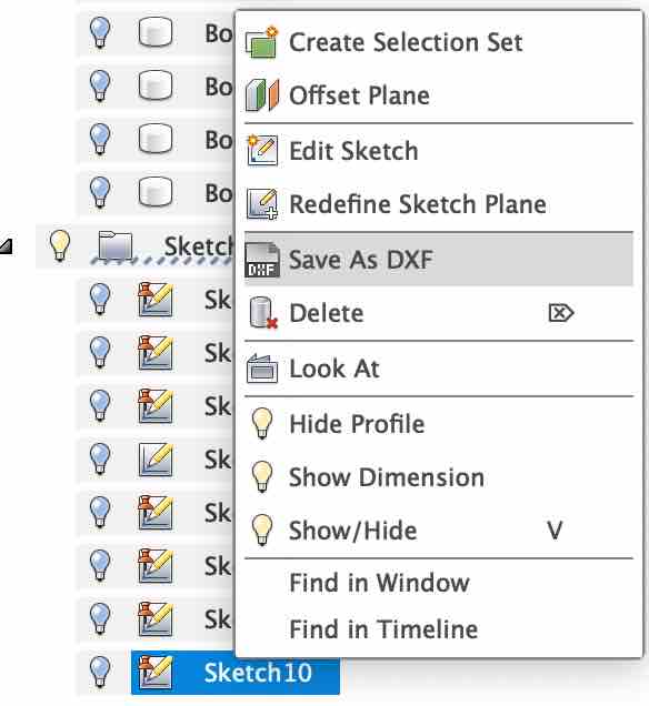
Once the pieces where ready, Istarted a new sketch on the top face of the profile and then projected the body onto the new sketch. This is to make sure all component details are included since some fillets where added after drawing the sketch and extruding the body. I set projection link on so that this projected sketch would update if any parameters where changed. Once the bodies were projected, I right clicked on the sketch and chose save as DXF. I know this isn't a preferred file format, however it is the only output from fusion.
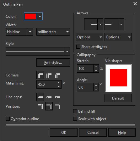
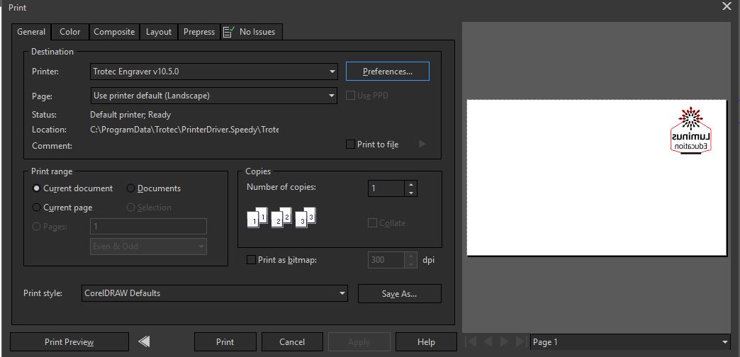
The DXF files were then opened in coral draw and the line color changed to RGB Red(255,0,0) and ensured the line thickness was "Hairline". Then I send the printed the file to Trotec's Job control, by specifying the printing area, dimensions and layout.
Line settings
Coraldraw print window
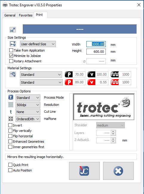
Trotec print settings
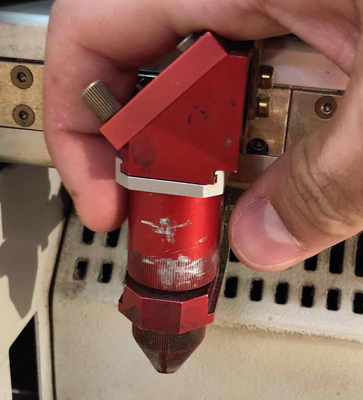
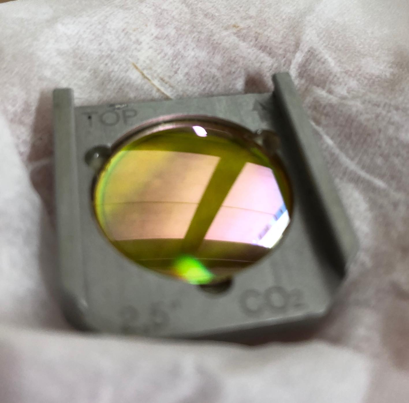
Before starting the cutting process, I had to clean the lense. This is done by undoing the screw and carefully removing the lense. Then using lense cleaning wipes or a lense cleaning cloth and some spray made sure all dust was removed and waited for any liquid to dry before reinserting it into the cutting head.
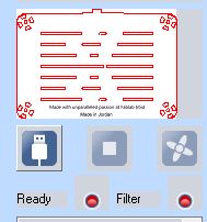
First click on the USB icon on the bottom right in Job Control to connect to the COM of the lasercutter, then wait for the connection to be conpleted. To start the cutting setup, the job had to be selected from the job list on the right and placed on the desired area of the bed.
Connect to lasercutter
Wait for connection
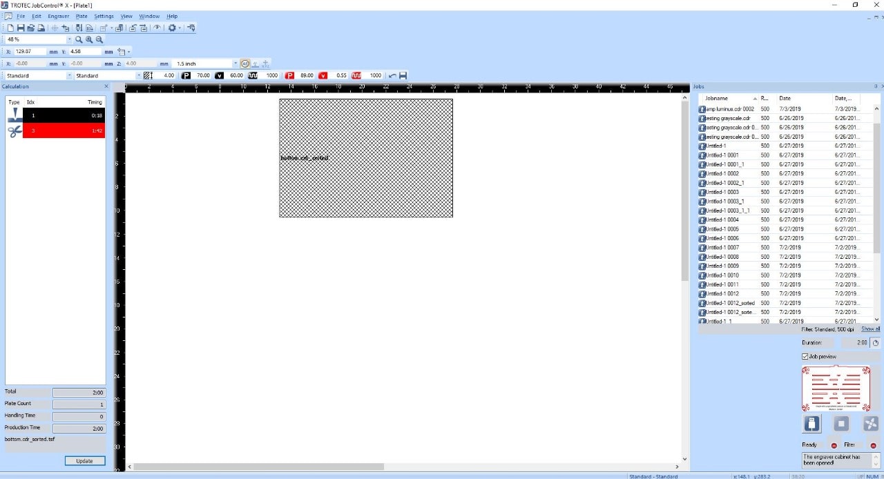
Job qeue and virtual bed
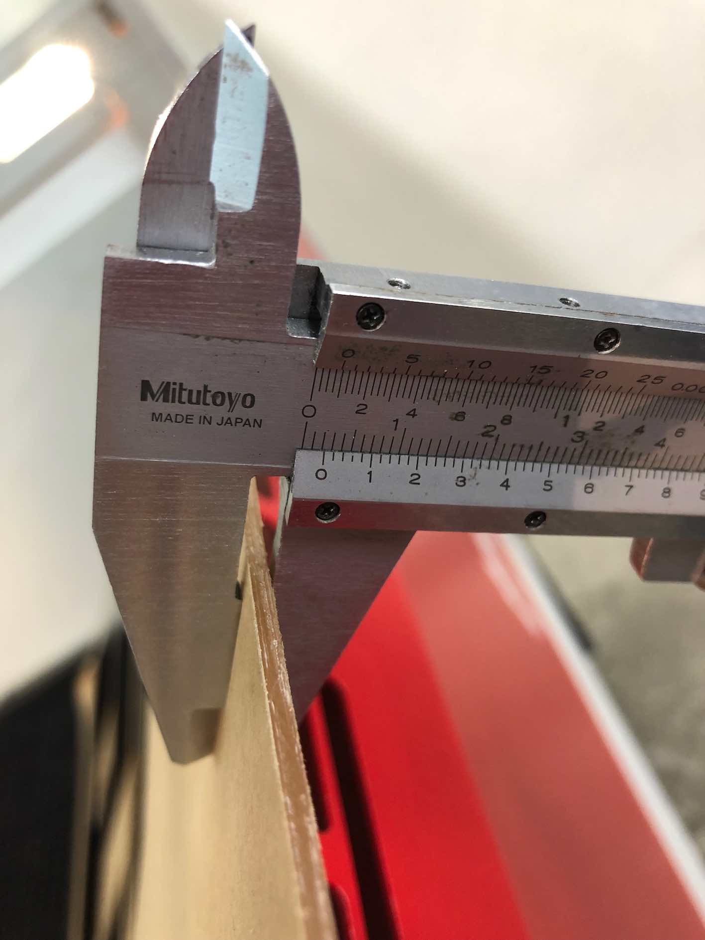
Then to enter the correct settings, use a caliper to measure the width of the material being cut to ensurethe head doesn't touch the material.With a thickness of 2, I specified the settings, in this case since I was cutting cardboard, and so I chose a higher velocity at 2.85 to avoid burning and frequency of 1000, power was set 89% and thickness of 2.2, just incase the cardboard slightly rose off the bed. This is all specified from the toolbar shown below, which is located in the top of the Job Control window.
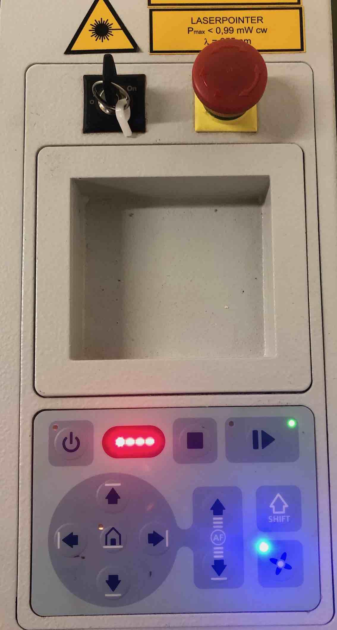
During the cutting process, keep an eye on the lasercutter and do not leave it unattended. the on-board control panel, allows you to pause or stop the process. The red stop button, is to completely stop the process incase of an emergency. It also allows manual movement of the bed and laser head pre-process.
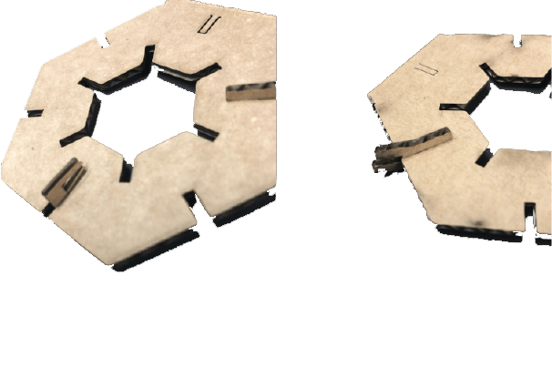
After cutting a test piece, I realised the joints were too short, so I tweaked the parameters and proceeded cutting the modified joints
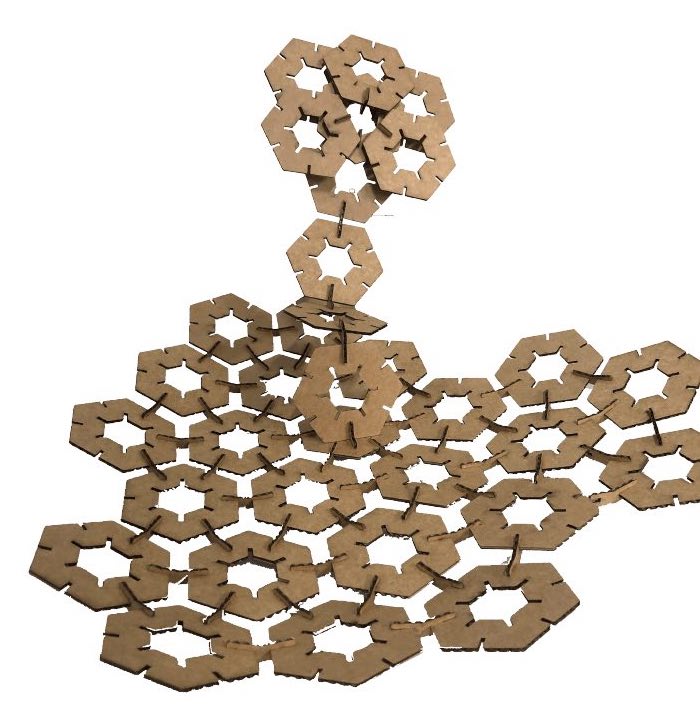
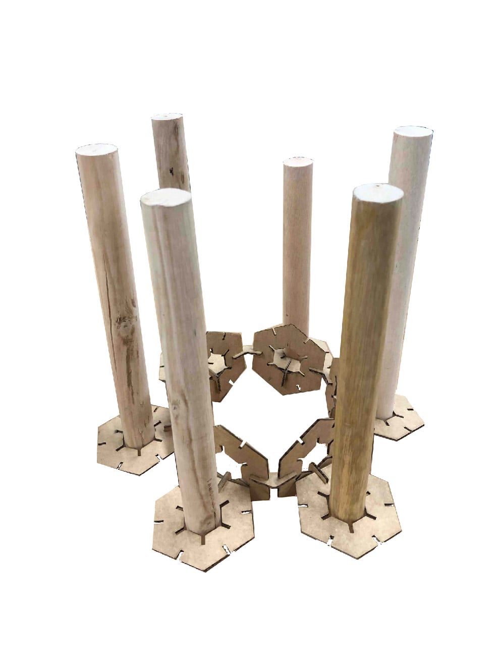
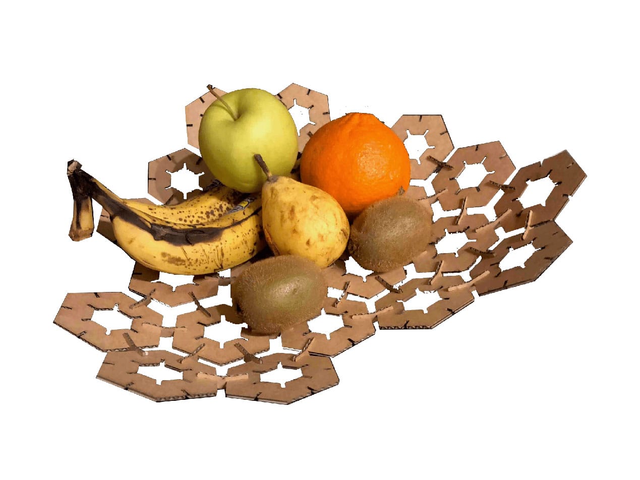
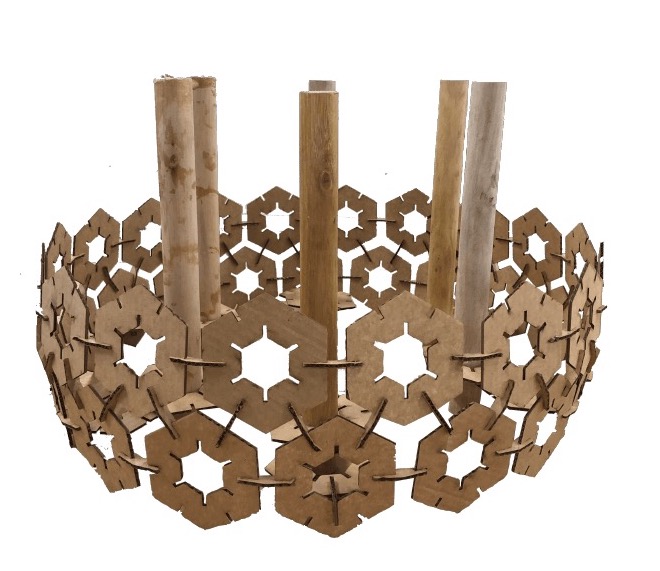
The next part took me back to my childhood, seeing where my imagination can take me trying to build whatever I can. Initially I started with a pavilion, but midway realised it can be a fruitbowl. Then I reconnected the pieces and made them into candle chandeliers/holder. Although, it's not the safest idea, the same concept can be applied to acrylic for example
Testing Living Hinges
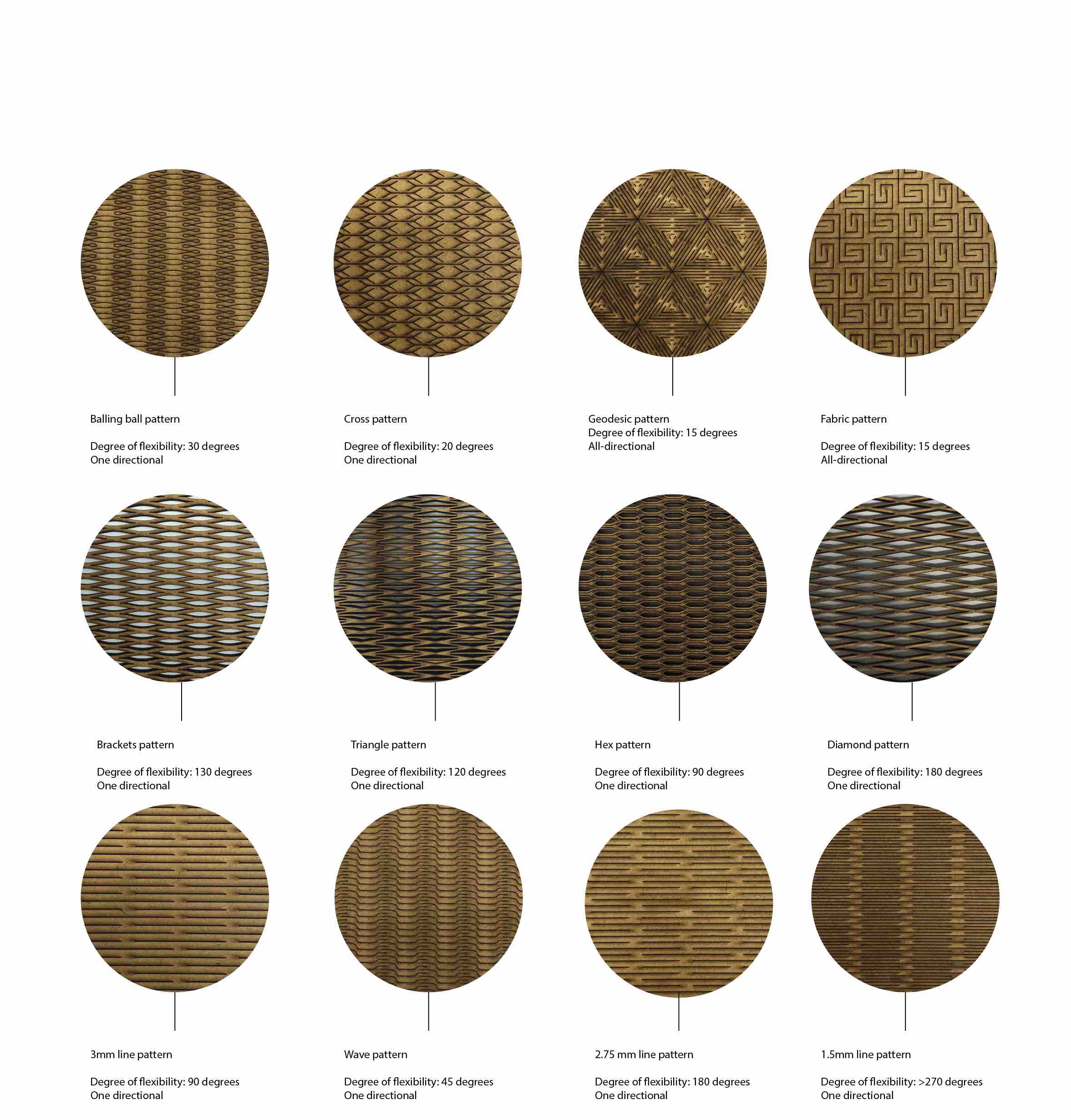
Ever since I had my first visit to a Fablab, I have been facinated with the concept of living hinges and changing the properties of solid materials using cut patterns. I decided to cut a number of patterns, test out the different properties, then put them together into a small living hinge booklet gallery (whatever didnt snap during testing). I found the patterns through this website and placed them into the laser cutting software, which gave me an estimate of ~1 hour per pattern. So I went back to the design and found out that the curves weren't connected. With a simple combine then join curves command on Coral draw, the time went down significantly, so I moved on to cutting them.
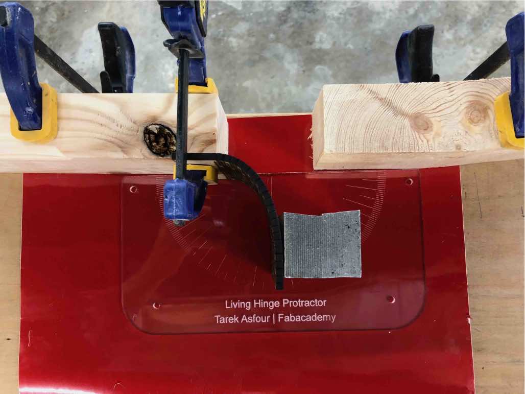
I then designed a protractor, laser cut it and placed it on a red vinyl sheet to help in testing the properties of each pattern.
The patterns were ready files and with minimal resizing of the border were reprinted. The same settings shown below were also used for the 5mm MDF laser-cutting of the cajon.
Making the Cajon
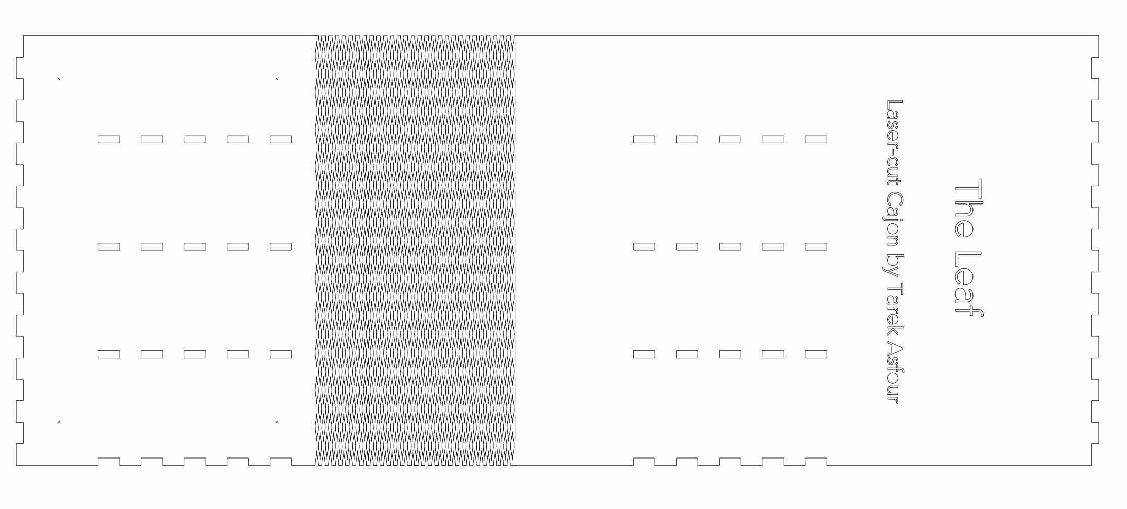
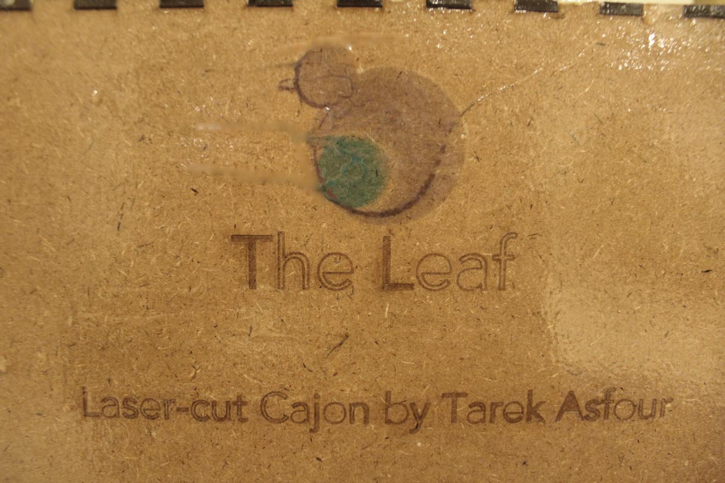
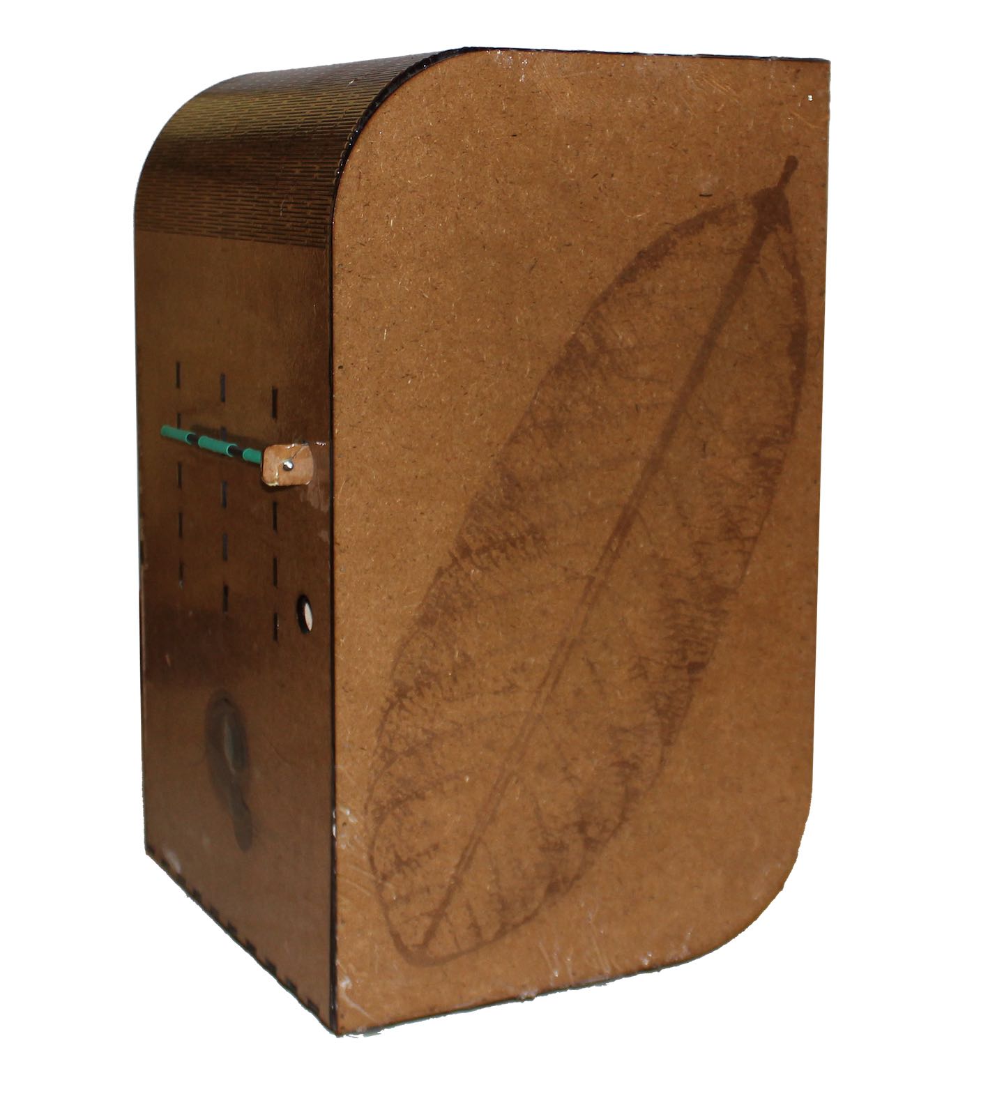
The mini project for this week to bring various vinyl prints/cutting and laser-cutting techniques together was my take on a cajon. A cajon is a Peruvian snare drum which consists of wood and a snare pushing against the front wooden membrane. I decided to call this design the leaf due to its diagonally symmetric shape and the engraving which I will explain in the coming sections.
First step was designing the body of drum and then diving further into the details, incorporating new techniques as I progress. The body was designed out of 4 outer pieces, using square pattern joints and including a straight kerf pattern of 2.25 mm from the previously tested patterns. The way the pattern was included was as follows, I measure the mid length of the curved edge and added it as a square in Adob illustrator. I then fit the pattern within the bordered area.
The inside of the drum had to be hollow, but since 5mm MDF was being used, it will not be enough to sustain the weight of a person, especially if he was over 90 KGs. I therefore added inner scaffolds that were hollow in the middle (so as not to affect the sound) that had extrusions that would fit within the outer frame.
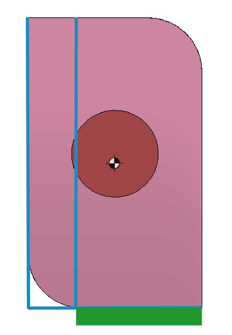
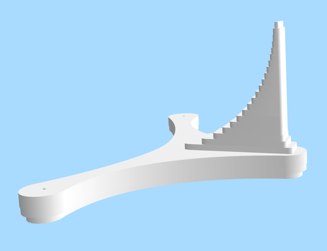
Next step was the base. Since the design had one bottom corner that was filleted, this meant that the weight would not be distributed equally. As seen on the left the center of gravity the center of gravity was located on far left to the contact points on the base which would cause instability.
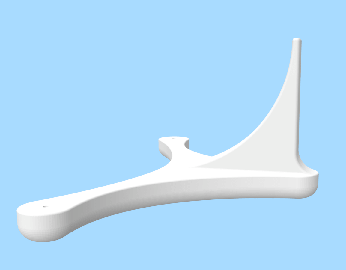
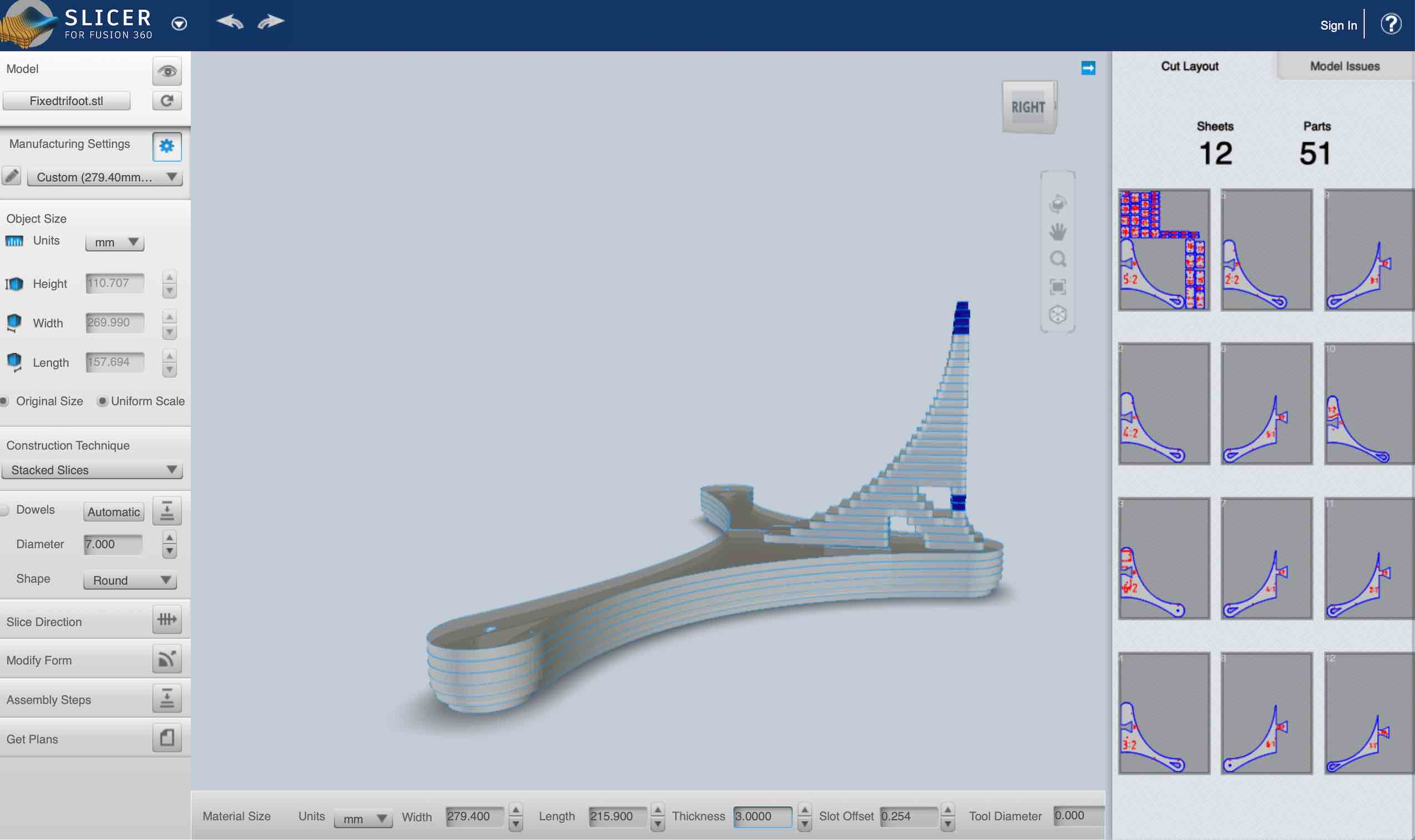
I designed a base with two attachable contact points and a curved contact surface, which supports the rounded bottom corner. The base consisted of two other seperate fee that were placed on the bottom corners by the straight edge(it will be clearer after looking at the pictures). In order to be able to produce the base using a laser cutter, I resorted to using Fusion 360s sliver to slice it into 3mm clear acrylic pieces. It was only after cutting and gluing then that I was told that it would’ve been better if this was achieved using interlocking joints instead of glue.
Solid base
Slicer settings
Sliced base
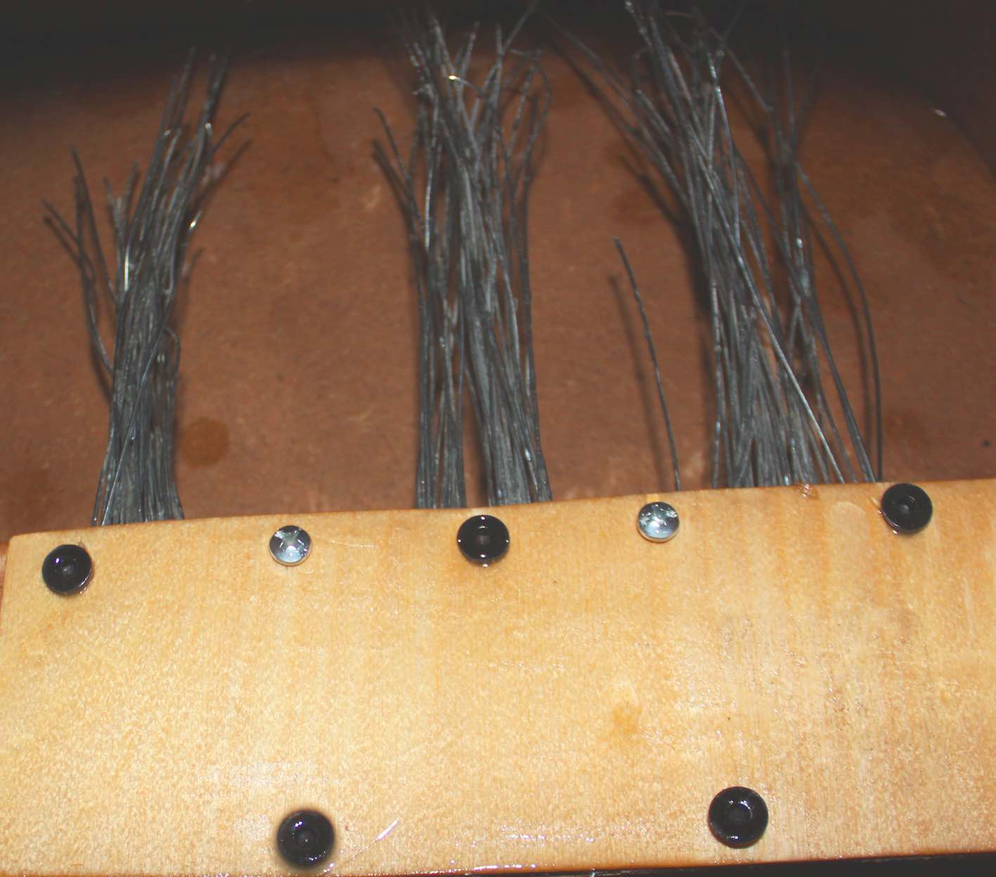
For the snare mechanism, I found it extremely hard to source the snare and came up with a simple alternative. I had one wooden piece which was hinges through both sides to control the snare and another piece from the inside screwed against it. I cut some 1 mm steel wire into ~10 cm strips and fixed them in between both wooden plates.
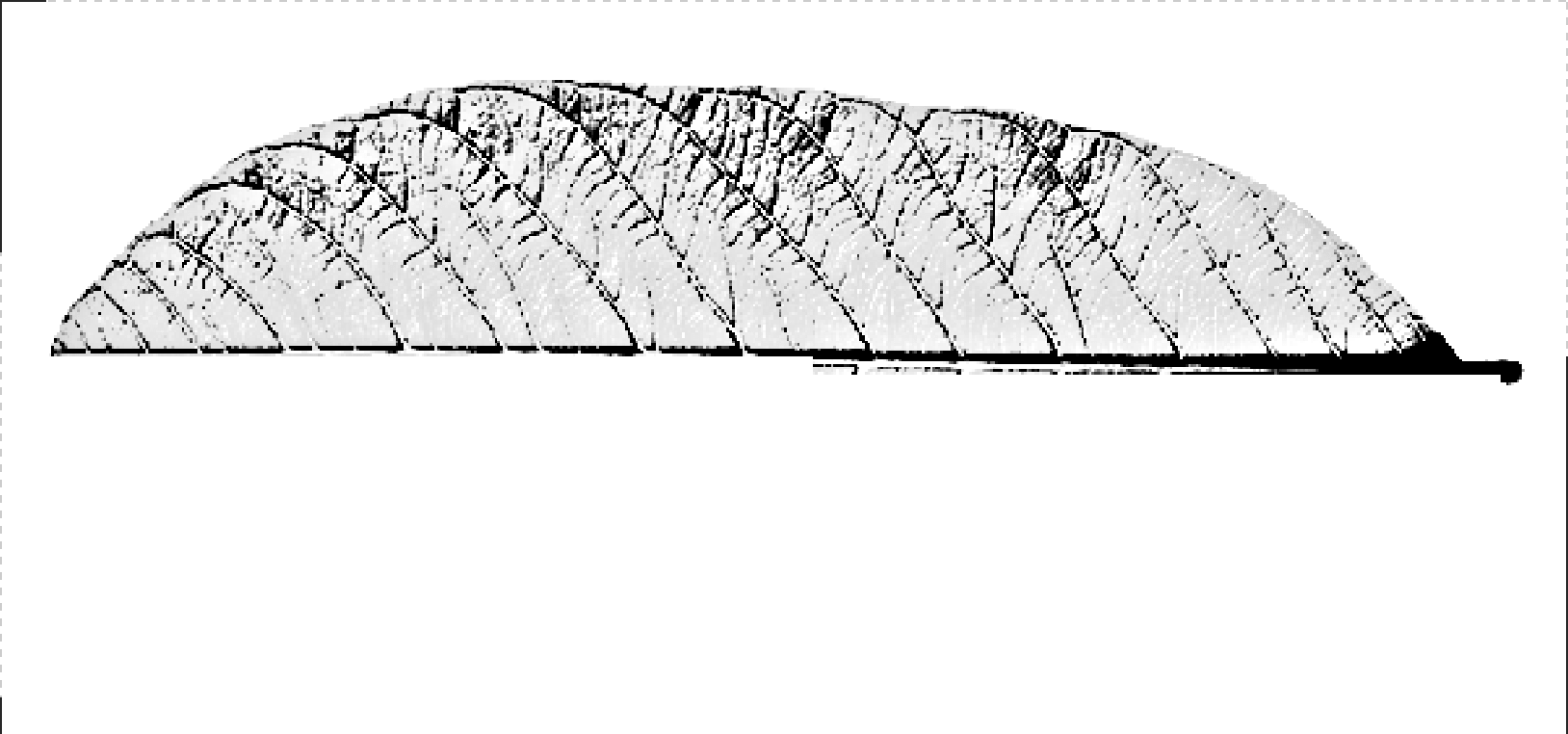
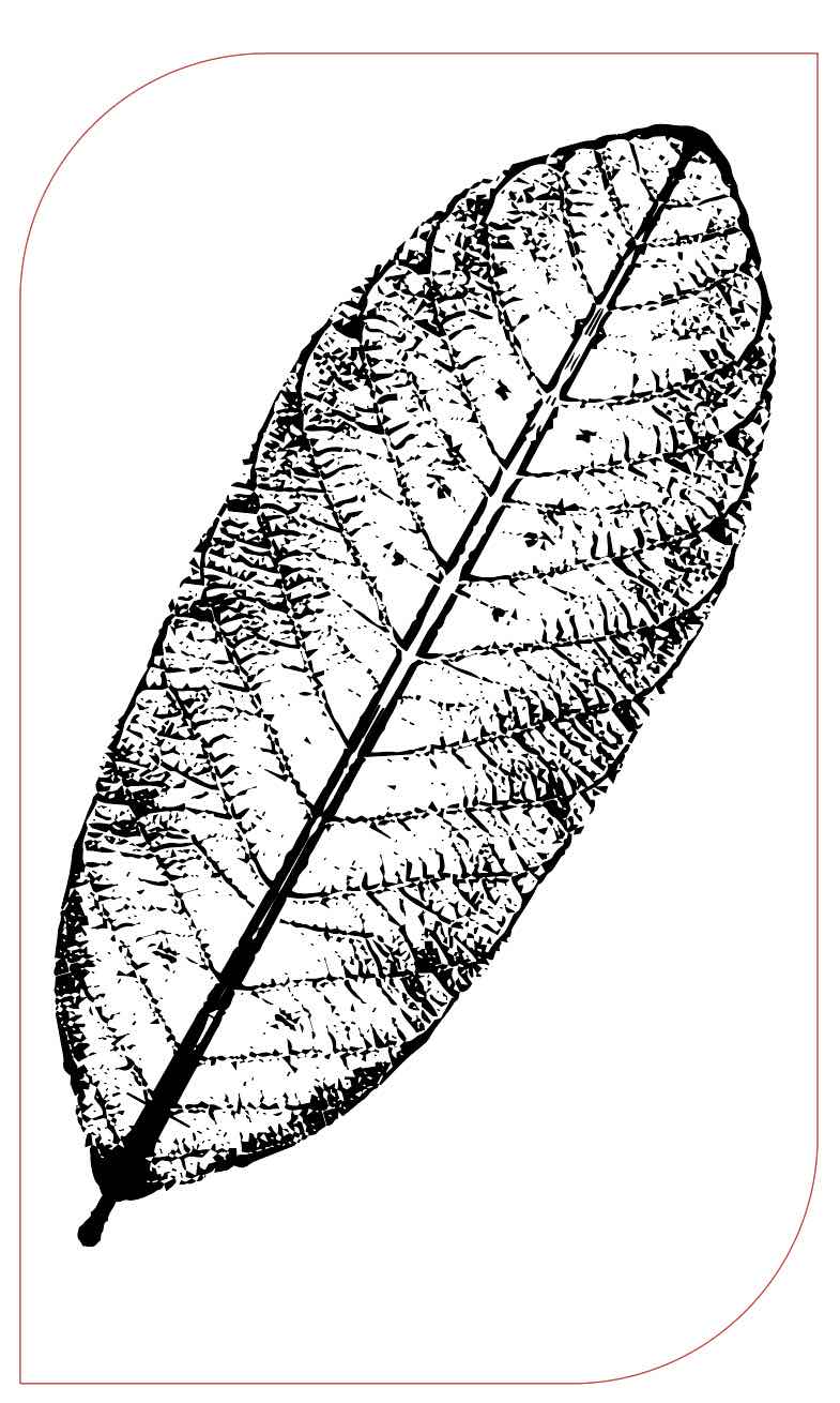
Lastly, I wanted to add some finishing touches before moving to the coating and painting process. I decided to attempt laser engraving an image. As mentioned earlier, I named the design "the leaf". So, it would go without saying that it had to include a leaf. Since it is a peruvian instrument, I settled on the Guava leaf, a beatiful leaf native to peru and its surrounding region. To do this I used Adobe illustrator. First step I made the changed the image into grayscale from the image menu and cropped it in half to ensure symmetry.
The next step was converting the image to a bitmap, choosing the correct settings, after which I duplicated and reflected the image to form the full leaf
Bitmap menu
Bitmap option
Full leaf
Once the laser-cutting was done, I added some vinyl stickers of my logo. Since the logo was already in vector format, all i had to do was merge the oultine paths and colour it using the Roland Versaworks cutting swatch. The rest was done exactly as the catterpillar sticker.
With the various parts put together, I moved on to the finishing proces and coated the whole assembly with epoxy resin. This served to both make the MDF more aesthetic as well as strengthen the physical properties of the MDF. It was a complete product, but design-wise not quite there. I felt It required an additional artistic touch. Since, I am not an artist, I decided to hand it over to a friend to add some peruvian style patterns and bring the product to life.
Painted version
Taking the cajon for a test run
Files
Please find all the files required, if you feel like making your own:

-min.png)