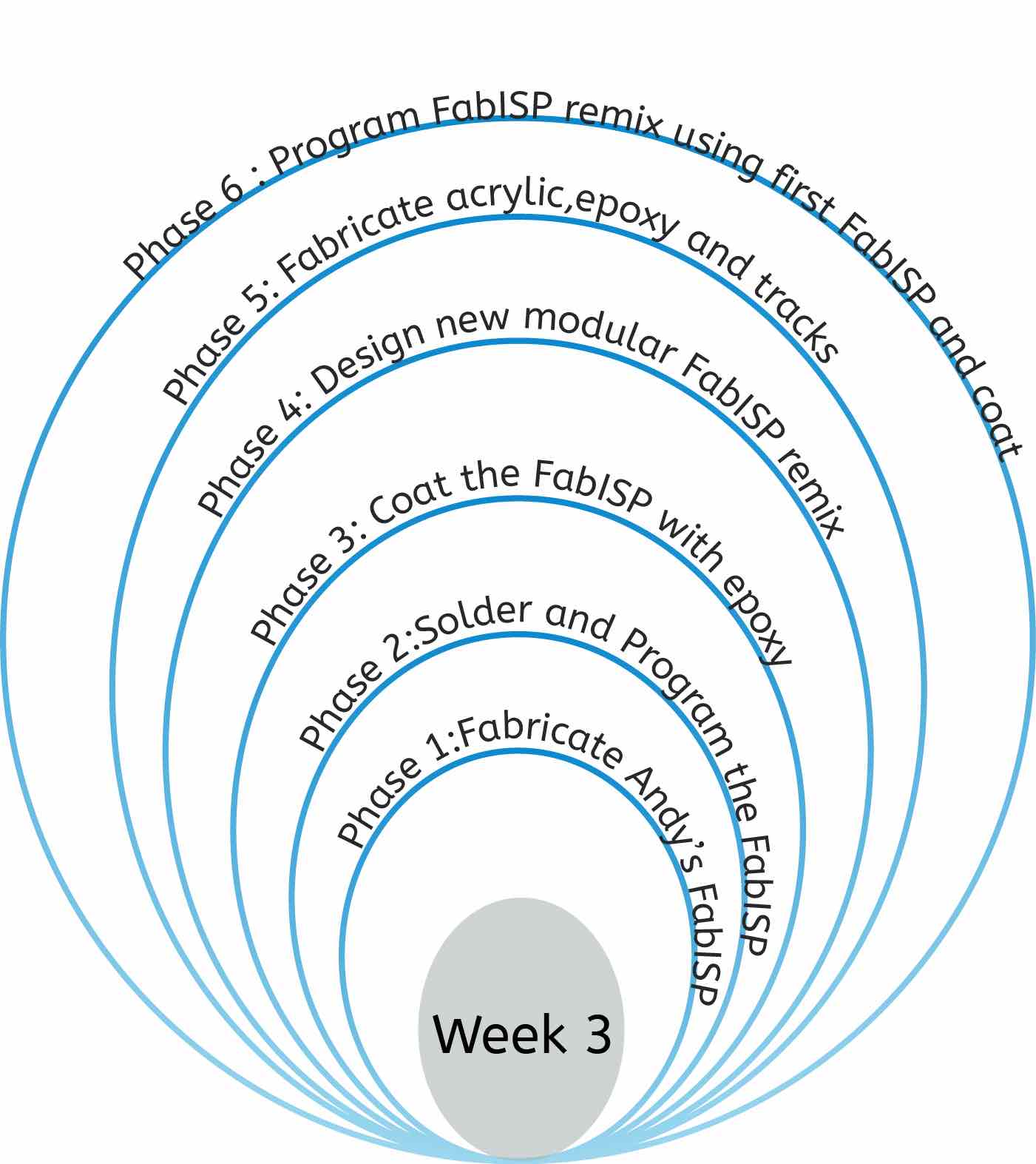
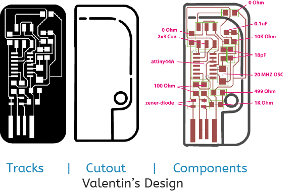
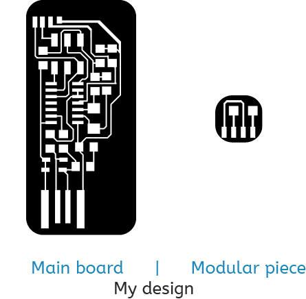
This week entails fabricating and programming a FabISP, I initially picked Andy's board to fabricate using the stardanrd techniques. Looking at the approaches and techniques used to fabricate the given FabISP examples, I was inspired by Valentin's breakout programmer module and Victoria's variegated vinyl acrylic board for my second board. I decided that after successfully producing a FabISP using the milling machine, I want to employ both techniques mentioned in conjunction with each other to produce a modular board with can be reprogrammed by attaching to it a modular piece. As with prior weeks, a spiral approach will be used to which I have constructed a basic clamshell plan.
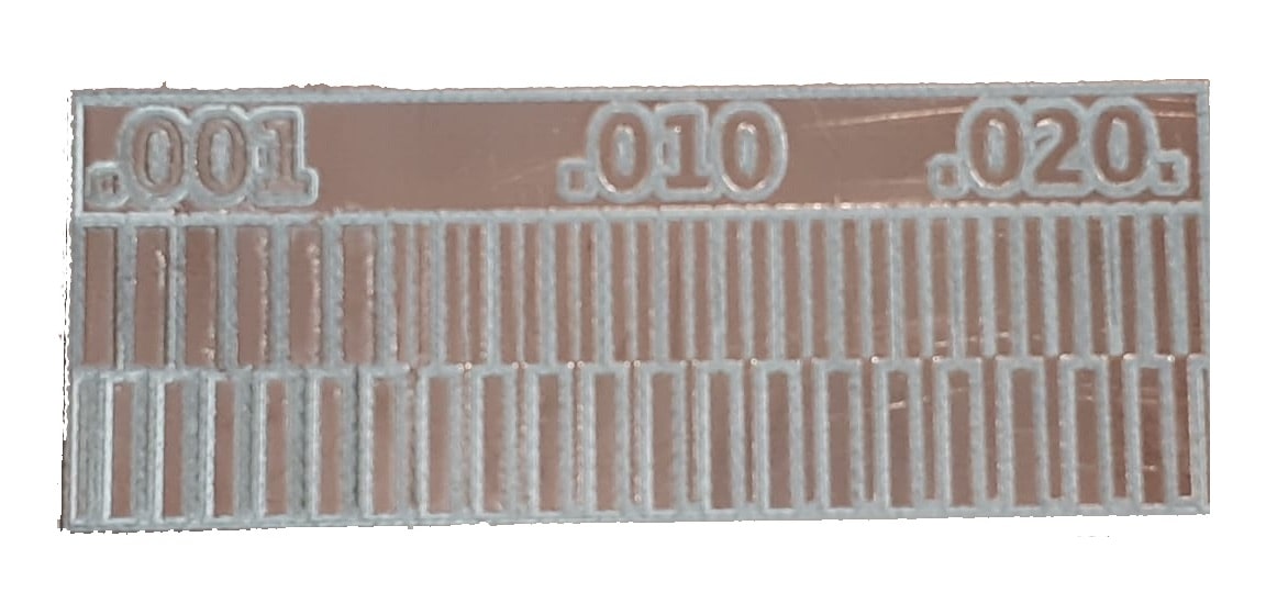
Group task: Measuring the endmill's precision
For this weeks group assignment we had to characterize the design rules for our PCB production process. We used the calibration comb to measure the precision capabilities of the machine and endmill to cut around and outline of a track as well as a line through a solid copper area.
Fabricating a basic FabISP
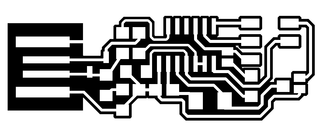
A Number of FabISP designs were provided for us as part of this week’s material. I chose Andy's Design as it was efficiently designed, yet wasn’t too challenging for someone who’s new to SMD soldering. I downloaded the milling and cutting .png images shown below and had to calibrate the Roland monoFab SRM-20 before starting the milling process.
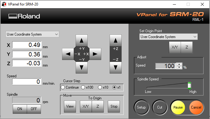
To calibrate the machine I first loaded the endmill , choosing to use a 0.2-0.5mm Since the required precision was 1/64 inches, which is equal to 0.4mm. Then, I calibrated the machine through the Roland Vpanel Software. As seen in the screenshot when moving the milling head, you can specify the magnitude of the increments. I secured my FR1 copper board to the bed using blue-tack. Starting off with a continous increment then slowly decreasing as I near my zero point, I homed my X and Y axis.
For the Z axis, I initially used the increments to find the machine zero, after which I lossened the tip allowing it to drop down to the bed. Then using the multimeter, I decended the head by increments of 0.01mm until there was conduction through contact between the head and the board. Now that the machine was centered, I set this position as the zero home point for all axes.
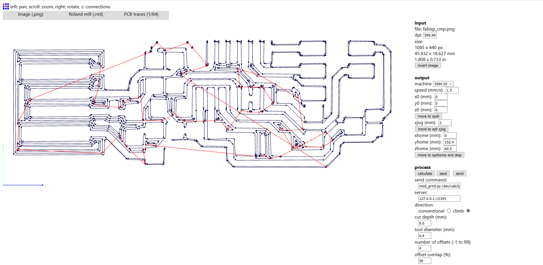
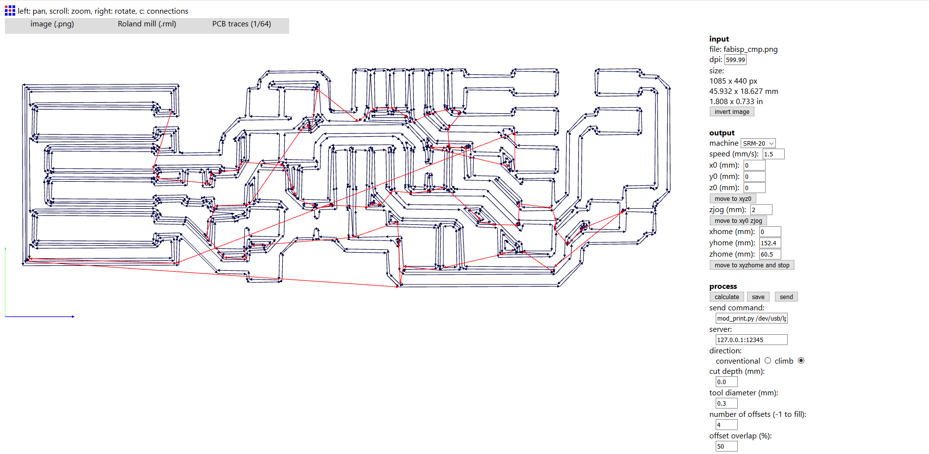
Now that the machine was zeroed, I was ready to start cutting. I uploaded the carving file to Fabmodules to specify the settings and output the .RML instruction code for the machine. I initially tried with a 0.4mm tool diameter setting, but some of the details, mainly the Attiny's contact points were showing as incomplete. A simple change of the tool diameter to 0.3mm solved the problem as seen in the screenshots below. Then I uploaded the code to the machine and set it to run. It is key to raise the Z axis before starting the cut, just incase the bed starts moving, to avoid snapping the endmill. The machine then milled around the tracks.
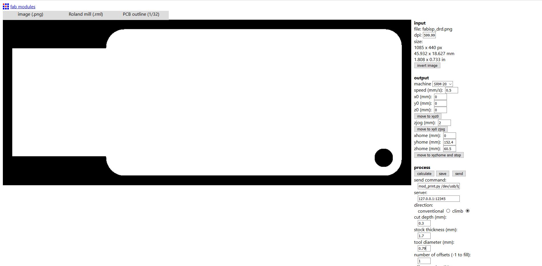
I repeated this process for the cutting of the board with a few changes to the settings. The traces were changed to 1/32, the speed taken down to 0.5 and I set the material thickness to 1.7mm and depth per cut of 0.3mm
Here is a timelapse of the whole process. Unfortunately during the first attempt, the endmill was slightly damaged and wasn't able to cut through correctly. After changing the endmill and preserving the same settings, the PCB was cut flawlessly.
Soldering FabISP's components
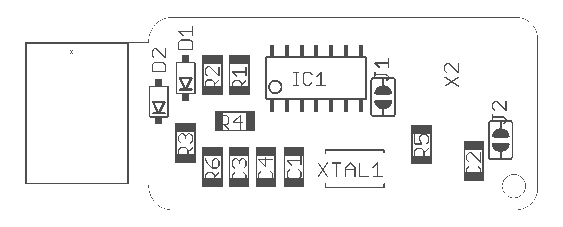
It was my first time doing surface-mount soldering and a while since I've done any kind of soldering. I first practiced the technique with some scrap components before starting with my board. The soldering iron was set to 340 degrees celcius?? and for most components some solder was placed on the board at one point of attachment, as per Dr. Neil's reccomendation. This allowed me to only need two hands, holding the component with tweezers in on and a solder iron in the other, without the need for a solder wire when first fixing the component. Once fixed the other contact points can be soldered normally with a solder wire and iron. I followed the diagram below to place the components correctly.
ID
Component
Quantity
XTAL1
20 MHz Crystal
1
IC1
Attiny44
1
X2
2X3 connector
1
D1/2
Zener Diode 3.3V
2
R5
0 Ohm resistor
1
R1/2
100 Ohm resistor
2
R6
499 Ohm resistor
1
R3
1K Ohm resistor
1
R4
10K Ohm resistor
1
C3
0.1 uF capacitor
1
C4
1 uF capacitor
1
C1/2
10 pF capacitor
2
Programming FabISP with Arduino
To program the ISP I followed the instructions required for my Mac on . It can be done on any operating system, but would be easier if it is a linux-based system. I had to download the FabISP firmware, XCode and Crosspack AVR.
Once the required files are downloaded, I unzipped the firmware folder. I opened the make file contained within the firmware folder and edited AVRDUDE = avrdude -c stk500v1 -b19200 -P /dev/cu.usbmodem14201 -p $(DEVICE)
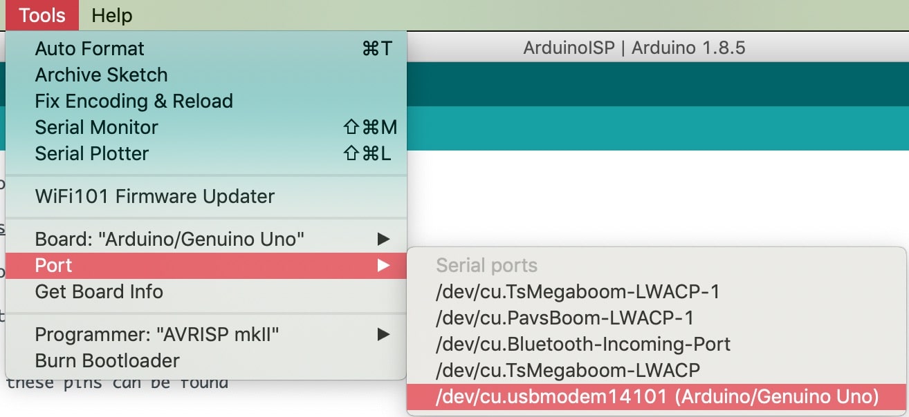
#AVRDUDE = avrdude -c avrisp2 -P usb -p $(DEVICE) # edit this line for your programmer uncommenting the first line shown above and adding the respective port and commenting out the second line out. To find the port, I simply opened the Arduino IDE and checked through there since I was using and Arduino Uno as a programmer.If using the Arduino upload the ArduinoISP sketch located in the IDE examples
Then through terminal access the firmware file
cd desktop/fabISP_0.8.2_firmware
then to make sure any unneeded previous compiled files are deleted. Also if any of the commands dont work, you can place the sudo statement to execute the commands as system root admin.
make clean
then compile the programming code by executing
make hex
then create the fuses to use the external clock
make fuse
or alternatively/ proceed to create the fuses and flash the program to your board in one command
make program
This is all the code needed to successfully program the Attiny44 as an ISP. There are other commands available but these should suffice for our usage.
The error shown on the right kept coming up, even after checking all the tracks. After reading on some forums where people faced the same problem, I decided to replace the ATtiny44 chip. The process is a sensitive process because if one isn't careful, you might rip the tracks off. I slowly heated the IC's joints up using a head gun while applying slight pressure to pluck it up.
avrdude: Device signature = 0x000000
avrdude: Yikes! Invalid device signature.
Double check connections and try again, or use -F to override
this check.
avrdude done. Thank you.
make: *** [fuse] Error 1
The old Attiny44 slowly peeled off and after installing a new Attiny44, I checked the connections then connected it to the Arduino Uno. Sure enough, the board functioned as planned and I was able to program it. The terminal window yielded the following output.
avrdude: Device signature = 0x1e9207
avrdude: NOTE: "flash" memory has been specified, an erase cycle will be performed
To disable this feature, specify the -D option.
avrdude: erasing chip
avrdude: reading input file "main.hex"
avrdude: writing flash (2002 bytes):
avrdude: verifying ...
avrdude: 1 bytes of lfuse verified
avrdude: safemode: Fuses OK (H:FF, E:DF, L:FF)
avrdude done. Thank you.
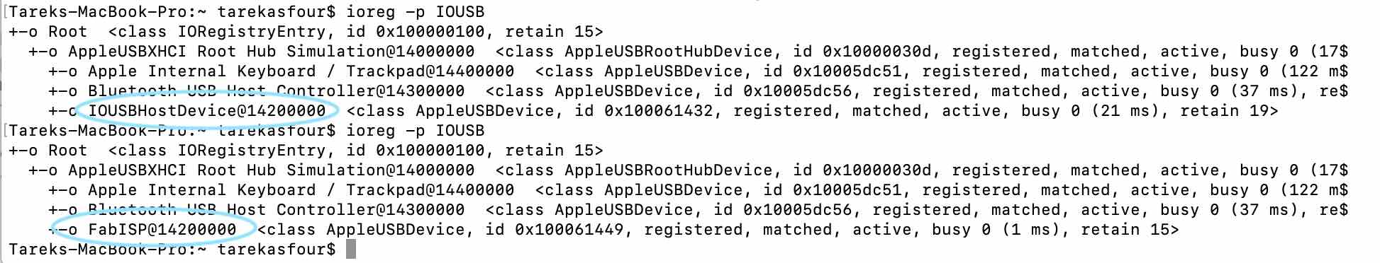
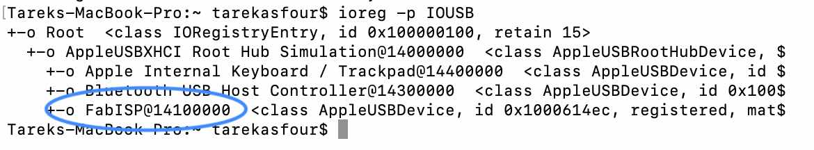
To check that the FabISP is functioning correctly I connected it using a USB extentionto my computer and through terminal ran the ioreg -p IOUSB. This produces a list of the attached devices and the FabISP can is connected. Now that it's been checked I went on and desoldered the jumper wires to turn it into a programmer rather than a programmable IC.
                Tareks-MacBook-Pro:~ tarekasfour$ ioreg -p IOUSB

+-o Root  < class IORegistryEntry, id 0x100000100, retain 15 >

  +-o AppleUSBXHCI Root Hub Simulation@14000000  <class AppleUSBRootHubDevice, $

    +-o Apple Internal Keyboard / Trackpad@14400000  <class AppleUSBDevice, id $

    +-o Bluetooth USB Host Controller@14300000  <class AppleUSBDevice, id 0x100$

    +-o Internal Memory Card Reader@14700000  <class AppleUSBDevice, id 0x10005$

    +-o FabISP@14200000  <class AppleUSBDevice, id 0x10005e34d, registered, mat$
Designing and making my FabISP remix
For additional practice and experimentation I was inspired by both Valentin’s detachable part and Victoria's variegated vinyl technique. I wanted to fabricate a board that could be reattached and not for a one time programming use. This would also allow one programming module for several ISPs. To do this I first downloaded Valentin's design and tweaked the detachable circuit to make it attach from one point common point on the board. I was able to alter the tracks on Adobe Illustrator by drawing simple black shapes to cover cancelled tracks and white ones to represent the new ones. This was the resulting design.
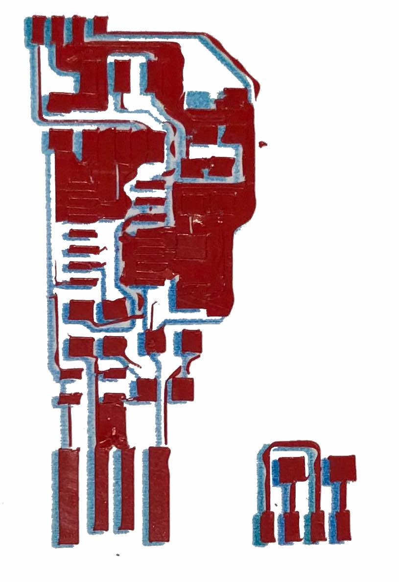
Now that I had the circuit design, I went on to prepare the design to be vinyl cut and the tracks colored from the bottom. However, when attempting to follow along Victoria's tutorial for vareigeted vinyl, the documentation was too brief for it to be repeatable. Hence, I formulated my own approach which was less limited in terms of colors and shapes. I decided to print on a sheet of clear vinyl, then stick a patch of copper vinyl over it then cut the tracks only on the first layer of copper. To prepare the design, I imported image of the tracks into illustrator and using the image trace command, I transformed it into vector shaped that I’d be able to color and cut. I created a copy of the current layer to specify the cutting outline. To specify the cutting outline, I used the path finder tool to find the outline and then used the roland versaworks swatch to set its properties. At first I attempted the technique on white and red vinyl so as not to waste the copper.
Gradient and cut file
First attempt with red vinyl was hard to peel off as tracks were too narrow to stay intact
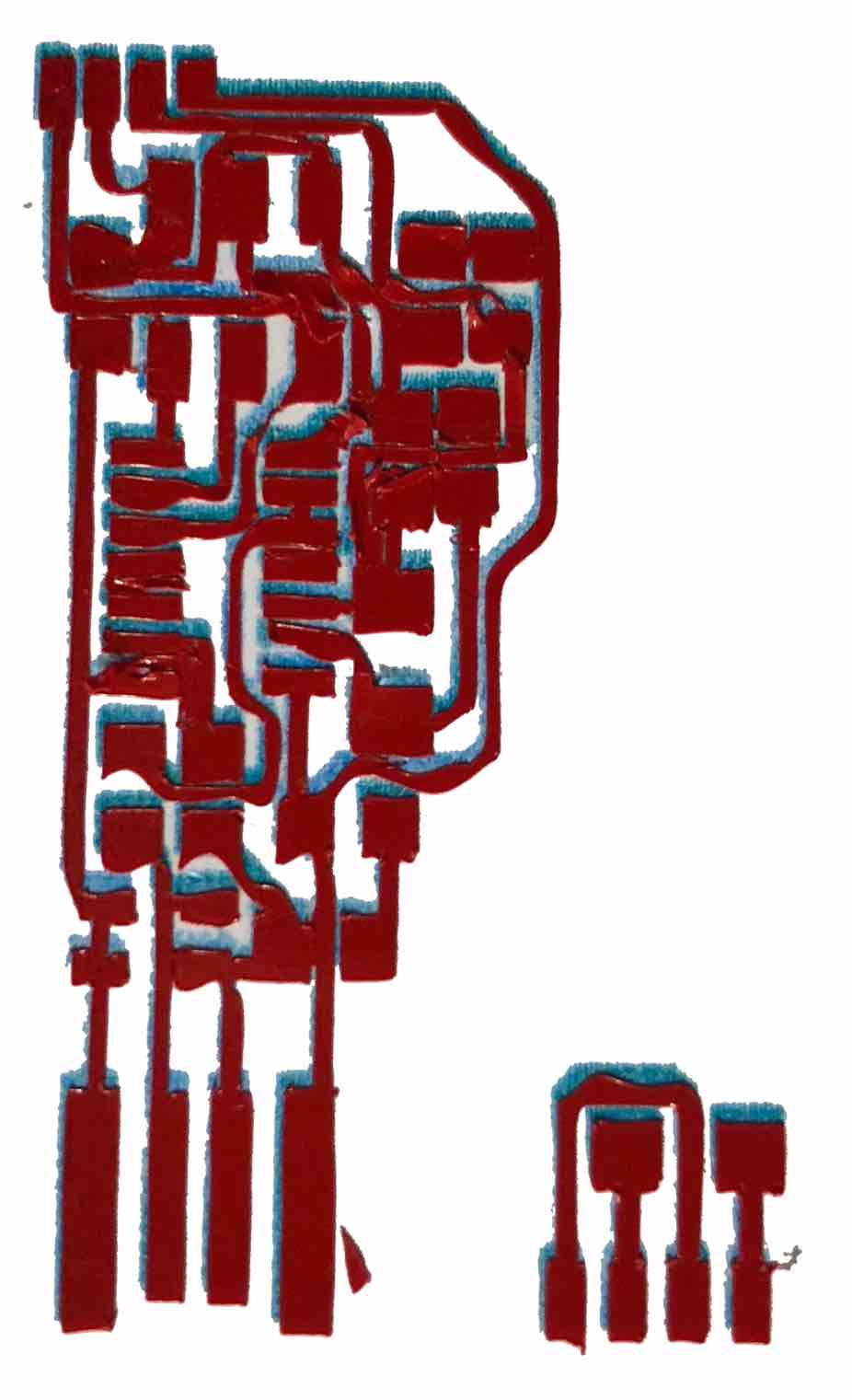
Second attempt with ammended tracks with increased width using red vinyl
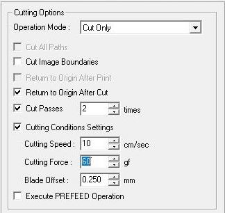
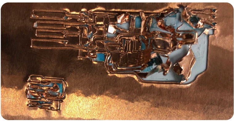
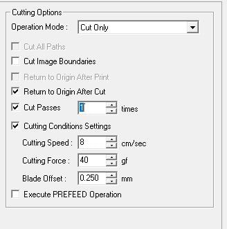
Now that the initial tests were over I attempted the technique using copper. The settings at first were to fast and the force was way too strong that the copper tracks were all torn out of place from the first pass. I toned down the setting and set it to cut in one pass and the result was pretty good.
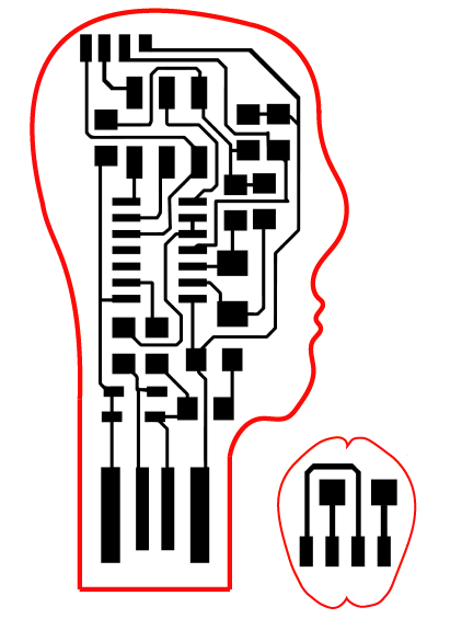
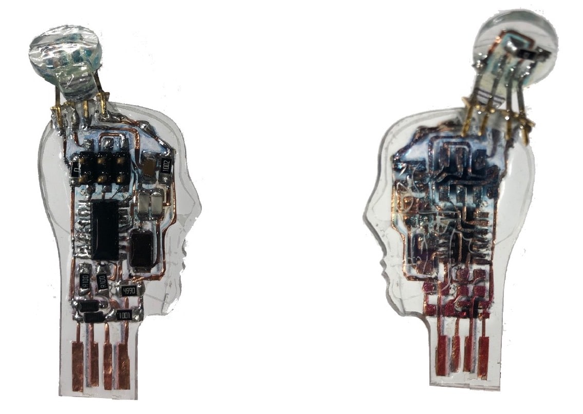
Before peeling of the empty areas of copper leaving the tracks layed over the clear vinyl, I had to laser-cut an acrylic base. Looking at the circuitry, I felt it resembled a human head and I drew an outline around the circuit resembling ahuman head on illustrator then proceeded to laser-cut it out of 2mm clear acrylic.The black color resembles engraving, red resembles cutting)
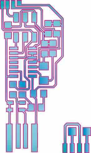
As seen on the left this was the first product before soldering on any components. I then decided to attempt again, fixing the narrow paths and flimsy corners, while also increasing the amount of color and design on the clear vinyl as this version merely looked like blue-colored mettalic copper tracks. The images below show the new laser cutout, with additional engraving, the new illustration as well as some slightly ammended tracks.
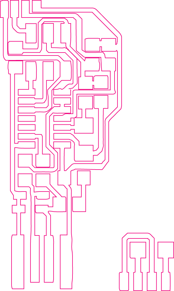
Final illustration to be printed on clear vinyl
Final FabISP track outline
Update acrylic design with additional skull engraving, in black.
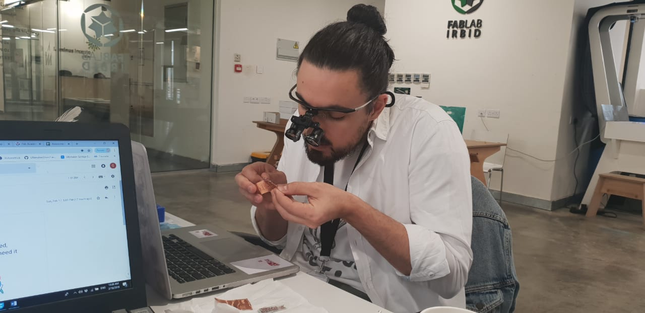
I repeated the same proces but used a surgical knife and tweezers with the help of some 3.5X magnifying loops to make sure all tracks stay intact. Soldering was done the same way as the first board but slightly quicker to avoid melting the clear vinyl layer. I then used some clear epoxy which is mixed with 2:1 ratio with a hardner, to coat the board and make sure the tracks are protected and refrain from peeling off.
Front side
Back side
Programming the my FabISP remix using the basic FabISP
Now that I had successfully produced the clear FabISP with colored tracks, I wanted to test the capabilities of the first fabricated ISP and use it to program this one. To achieve this, I first had to find the port. I connected the Arduino to the same port, used the IDE to find the port address and then proceeded to find the port number on terminal. When reconnecting the FabISP, it showed up on terminal with the same port number meaning it has the same address.
I naively thought the programming part is identical to that of the Arduino but turns out after some research its a much longer process so I decided to program it using the Arduino. Since there where no available 4-pin male and female connectors for the board and its modular part during fabrication, the pins I used were a bit loose. When I was testing the connections using the multimeter. I decided to implement a quick fix by temporarily soldering the connector pins to eachother to ensure they stay connected during programming. I proceeded with the compiling and flashing process as with the previous board. Afterwards, I could see the new FabISP when connecting it through a USB extention cord.
Heroshot
My boards that made me feel somewhere between a villain and a hero!
Files
Please find all the files required, if you feel like fabricating your own:
-min.png)